YAMZ1PF5TETRA Terminal
Hytera Communications Corporation Limited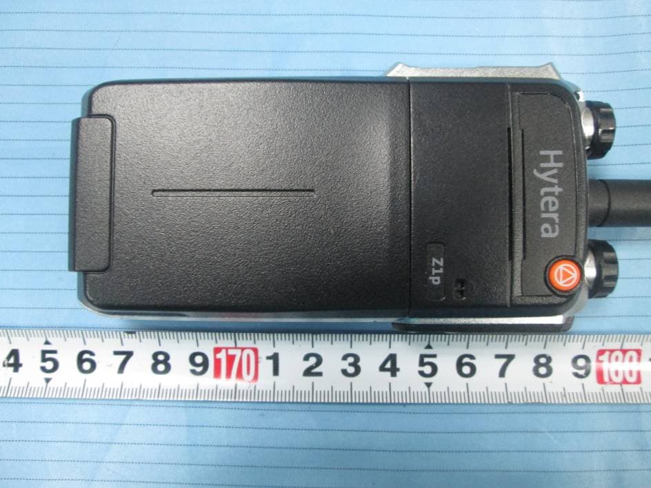
Click to zoom
Application Details
- Equipment Class
- DSS - Part 15 Spread Spectrum Transmitter
- Date of Grant
- Apr 26, 2015
- Application Purpose
- Original Equipment
- Date of Application
- Apr 26, 2015
- Equipment Note
- TETRA Terminal
- Frequency Range
- 2402.00000000 - 2480.00000000
- Country
- China
Documents & Files
Document Text
Text extracted from the exhibit documents filed with the FCC. Open a document above to read the original.
Users Manual
12 Preface Thanks for your favor in our product. To derive optimum performance from the product, please read this manual, the corresponding TETRA Terminal Series Feature Book and the Safety Information Booklet carefully before use. This manual is applicable to the following model: Z1p TETRA Portable Terminal 13 Term Individual Call A half-duplex or full-duplex call initiated by an individual user to another individual user. Group Call A half-duplex call initiated by an individual user to a group. Half-duplex Half-duplex communication is also called “two-way alternate communication”. It indicates the communication is provided in both directions, but only one direction at a time, that is, only one party is all owed to transmit or receive at a time. Full-duplex Full-duplex communication is also called “full-duplex synchronous communication”. It indicates the communication is allowed in both directions simultaneously, that is, both parties can transmit and receive at the same time. Direct Mode Operation (DMO) DMO supports half-duplex operation and allows the terminals to communicate directly with each oth er, without using a TETRA network infrastructure. Thus functions that require network access, such as telephone call, will be unavailable. Trunked Mode Operation (TMO) TMO supports either half- duplex or full-duplex operation and allows the terminals to communicate with each other via the TETRA network infrastructure. Thus functions that require network access are available. To operate in TMO mode, the terminal must be granted authorization by your service provider, and must stay within the network coverage. Disclaimer Hytera Communications Co., Ltd. (the Company) endeavors to achieve the accuracy and completeness of this manual, but no warranty of accuracy or reliability is given. All the specifications and designs are subject to change without notice due to continuous technology development. No part of this manual may be copied, modified, translated, or distributed in any manner without the express wri tten permission of us. We do not guarantee, for any particular purpose, the accuracy, validity, timeliness, legitimacy or completeness of the Third Party products and contents involved in this manual. If you have any suggestions or would like to learn more details, please visit our website at: http://www. hytera.com. FCC Statement This equipment has been tested and found to comply with the limits for a Class B digital device, pursuant to part 15 of FCC Rules. These limits are designed to provide reasonable protection against harmful interference in a residential installation. This equipment generates and can radiate radio frequency energy and, if not installed and used in accordance with the instructions, may cause harmful interference to radio communications. However, there is no guarantee that interference will not occur in a particular installation. If this equipment does cause harmful interference to radio or television reception, which can be determined by turning the equipment off and on, the user is encouraged to try to correct. The interference by one or more of the following measures: ● Reorient or relocate the receiving antenna. Increase the separation between the equipment and receiver. ● Connect the equipment into an outlet on a circuit different from that to which the receiver is connected. ● Consult the dealer or an experienced radio/TV technician for help Operation is subject to the following two conditions: 1. This device may not cause harmful interference, and 2. This device must accept any interference received, including interference that may cause undesired operation. Note:” Changes or modifications to this unit not expressly approved by the party responsible for compliance could void the user’s authority to operate the equipment.” Compliance with RF Exposure Standards Hytera’s 2-way radio complies with the following RF energy exposure standards and guidelines: • United States Federal Communications Commission, Code of Federal Regulations; 47 CFR §§ 1.1307, 1.1310 and 2.1093 • American National Standards Institute (ANSI) / Institute of Electrical and Electronic Engineers (IEEE) C95. 1-1992 • Institute of Electrical and Electronic Engineers (IEEE) C95.1-1999 Edition RF Exposure Compliance and Control Guidelines and Operating Instructions To control your exposure and ensure compliance with the occupational/controlled environment exposure limits always adhere to the following procedures. Guidelines: • Do not remove the RF Exposure Label from the device. • User awareness instructions should accompany device when transferred to other users. • Do not use this device if the operational requirements described herein are not met. Operating Instructions: • Transmit no more than the rated duty factor of 50% of the time. To transmit (talk), push the Push-To-Talk (PTT) button. To receive calls, release the PTT button. Transmitting 50 % of the time, or less, is important because this radio generates measurable RF energy exposure only when transmitting (in terms of measuring for standards compliance). • Hold the radio in a vertical position in front of face with the microphone (and the other parts of the radio, including the antenna) at least one inch (2.5 cm) away from the nose. Keeping the radio at the proper distance is important because RF exposures decrease with distance from the antenna. Antenna should be kept away from eyes. • When worn on the body, always place the radio in a Hytera’s approved clip, holder, holster, case, or body harness for this product. Using approved body-worn accessories is important because the use of Hytera’s or other manufacturer’s non-approved accessories may result in exposure levels, which exceed the FCC’s occupational/controlled environment RF exposure limits. • If you are not using a body-worn accessory and are not using the radio in the intended use position in front of the face, then ensure the antenna and the radio are kept at least 2.5 cm (one i…
Text truncated - open the document above for the full version.
Cover Letter(s)
Hytera Communications Corporation Ltd. Add: HYT Tower, Hi-Tech Industrial Park North, Nanshan District, Shenzhen China. 518057 Tel: +86-0755-26972999 Fax: +86-0755-86137130 FCC Authorization Date: 2015-03-06 FEDERAL COMMUNICATIONS COMMISSIONS Authorization and Evaluation Division 7435 Oakland Mills Road Columbia, MD 21046 Subject: Agent Authorization To whom it may concern: We Hytera Communications Corporation Ltd., the undersigned, Hereby authorizes Bay Area Compliance Laboratories Corporation to act on its behalf in all matters relating to application for Equipment authorization, including the signing of all documents relating to these matters. All acts carried out by Bay Area Compliance Laboratory Corporation on our behalf shall have the same effect as our own action. We, the undersigned, hereby certify that we are not subject to a denial of federal benefits, that includes FCC benefits, pursuant to Section 5301 of the Anti-Drug Abuse Act of 1988, 21 U.S.C. 862. This authorization is valid until further written notice from the applicant. Sincerely Yours, Signature: Lei Xiong General Director QA-FR-170-B
Cover Letter(s)
Hytera Communications Corporation Ltd. Add: HYT Tower, Hi-Tech Industrial Park North, Nanshan District, Shenzhen China. 518057 Tel: +86-0755-26972999 Fax: +86-0755-86137130 FCC Confidential Authorization 2015-03-06 FEDERAL COMMUNICATIONS COMMISSIONS Authorization and Evaluation Division 7435 Oakland Mills Road Columbia, MD 21046 Confidentiality request regarding application for certification of FCC ID: YAMZ1PF5 Pursuant to sections 0.457 and 0.459 of the Commission’s Rules, we hereby request confidential treatment of information accompanying this application as outlined below: Block Diagram--- (Long term) Circuit Description--- (Long term) Schematic--- (Long term) The above materials contain trade secrets and proprietary information not customarily released to the public. The public disclosure of these materials may be harmful to the applicant and provide unjustified benefits to its competitors. The applicant understands that pursuant to Section 0.457 of the Rules, disclosure of this application and all accompanying documentation will not be made before the date of the Grant for this application. Sincerely Yours, Signature: Lei Xiong General Director
External Photos
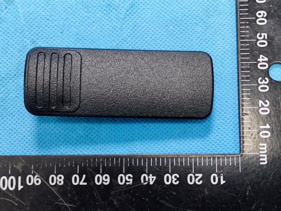
EXHIBIT B - EUT EXTERNAL PHOTOGRAPHS EUT – All View EUT – Front View EUT – Rear View EUT – Top View EUT – Top Port View EUT – Bottom View EUT – Left Side View EUT – Left Side Port View EUT – Right Side View EUT – Adapter View EUT – Adapter Label View EUT – Antenna View 1 EUT – Antenna View 2 EUT – Charger Front View EUT – Charger Rear View EUT – Charger Top View EUT – Charger Bottom View EUT – Charger Left Side View EUT – Charger Right Side View EUT – Charger Label View
ID Label/Location Info
EXHIBIT A - FCC ID LABELING AND LOCATION FCC ID Label Proposed FCC ID Label Location The label shown shall be permanently affixed at a conspicuous location on the device and be readily visible to the user at the time purchase (Labeling requirements per 2.925) Label here
Internal Photos
EXHIBIT C - EUT INTERNAL PHOTOGRAPHS EUT – Cover off View 1 EUT – Cover off View 2 BT Antenna EUT –Cover off View 3 EUT –Cover off View 4 EUT –Cover off View 5 EUT –Cover off View 6 EUT – Main Board Top View EUT – Main Board Top Shielding off View EUT – Main Board Bottom View EUT – Main Board Bottom Shielding off View EUT – Battery View EUT – Battery Label View EUT – Charger Cover off View 1 EUT – Charger Cover off View 2 EUT – Charger Main Board Top View EUT – Charger Main Board Bottom View
Test Report
Note: This test report is prepared for the customer shown above and for the equipment described herein. It may not be duplicated or used in part without prior written consent from Bay Area Compliance Laboratories Corp. FCC PART 15.247 TEST REPORT For Hytera Communications Co., Ltd. HYT Tower, Hi-Tech Industrial Park North, Nanshan District, Shenzhen, China FCC ID:YAMZ1PF5 Report Type: Original Report Product Type: TETRA Terminal Test En gineer: Candy Li Report Number: RSZ150205006-00B Re port Date: 2015-03-03 Reviewed B y: Jimmy Xiao RF En gineer Prepared By: Bay Area Compliance Laboratories Corp. (Shenzhen) 6/F, the 3rd Phase of WanLi Industrial Building ShiHua Road, FuTian Free Trade Zone Shenzhen, Guangdong, China Tel: +86-755-33320018 Fax: +86-755-33320008 www.baclcorp.com.cn Bay Area Compliance Laboratories Corp. (Shenzhen) Report No.: RSZ150205006-00B FCC Part 15.247 Page 2 of 62 TABLE OF CONTENTS GENERAL INFORMATION ....................................................................................................................................... 4 PRODUCT DESCRIPTION FOR EQUIPMENT UNDER TEST (EUT) ..................................................................................... 4 OBJECTIVE ................................................................................................................................................................... 4 RELATED SUBMITTAL(S)/GRANT(S) ............................................................................................................................. 4 TEST METHODOLOGY .................................................................................................................................................. 4 TEST FACILITY ............................................................................................................................................................. 5 SYSTEM TEST CONFIGURATION .......................................................................................................................... 6 DESCRIPTION OF TEST CONFIGURATION ...................................................................................................................... 6 EUT EXERCISE SOFTWARE .......................................................................................................................................... 6 SPECIAL ACCESSORIES ................................................................................................................................................. 6 EQUIPMENT MODIFICATIONS ....................................................................................................................................... 6 SUPPORT EQUIPMENT LIST AND DETAILS .................................................................................................................... 6 EXTERNAL I/O CABLE .................................................................................................................................................. 6 EUT ............................................................................................................................................................................. 6 BLOCK DIAGRAM OF TEST SETUP ................................................................................................................................ 7 SUMMARY OF TEST RESULTS ............................................................................................................................... 8 FCC§15.247 (i), §1.1307 (b) (1) &§2.1093 – RF EXPOSURE ........................................................................................ 9 APPLICABLE STANDARD .............................................................................................................................................. 9 FCC §15.203 – ANTENNA REQUIREMENT .......................................................................................................... 10 APPLICABLE STANDARD ............................................................................................................................................ 10 ANTENNA CONNECTOR CONSTRUCTION .................................................................................................................... 10 FCC §15.207 (a) – AC LINE CONDUCTED EMISSIONS ..................................................................................... 11 APPLICABLE STANDARD ............................................................................................................................................ 11 MEASUREMENT UNCERTAINTY .................................................................................................................................. 11 EUT SETUP ................................................................................................................................................................ 11 EMI TEST RECEIVER SETUP ....................................................................................................................................... 12 TEST PROCEDURE ...................................................................................................................................................... 12 TEST EQUIPMENT LIST AND DETAILS ......................................................................................................................... 12 CORRECTED FACTOR & MARGIN CALCULATION ....................................................................................................... 12 TEST RESULTS SUMMARY .......................................................................................................................................... 13 TEST DATA ................................................................................................................................................................ 13 FCC §15.205, §15.209 & §15.247(d) – RADIATED EMISSIONS .......................................................................…
Text truncated - open the document above for the full version.
Test Setup Photos
EXHIBIT D - TEST SETUP PHOTOGRAPHS Conducted Emissions - Front View Conducted Emissions - Side View Radiated Emissions View (Below 1GHz) Radiated Emissions View (Above 1GHz)
Contact Information
Applicant
Ruifen Huang(Certification Engineer)
Test Firm
Bay Area Compliance Laboratory Corp. (Shenzhen)John Chan
Technical Specifications
| # | Rule Parts | Frequency Range | Power Output |
|---|---|---|---|
| 1 | 15C | 2.40 GHz - 2.48 GHz | 5.00 mW |
Other Applications from Hytera Communications Corporation Limited
YAMBP516LF
Aug 15, 2022Digital Portable Radio
Equipment Class
FRF - Part 95 Family Radio Face Held Transmitter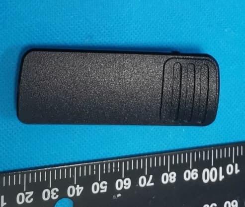
YAMBP5XXVHF
Mar 01, 2022Digital Portable Radio
Equipment Class
DSS - Part 15 Spread Spectrum Transmitter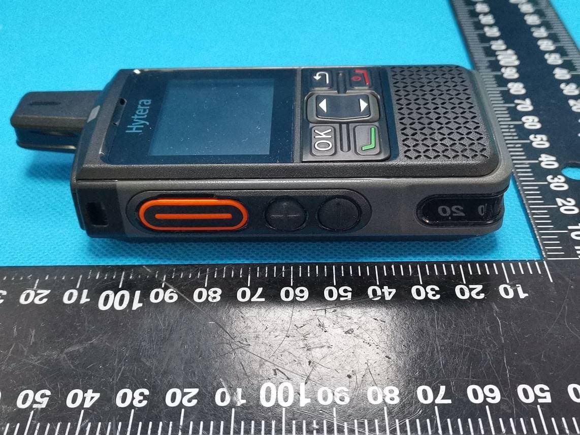
YAMPNC360S
Jan 19, 2022PoC Radio
Equipment Class
DTS - Digital Transmission System
YAMHM78XUVS
Jul 28, 2021DIGITAL MOBILE RADIO
Equipment Class
TNB - Licensed Non-Broadcast Station Transmitter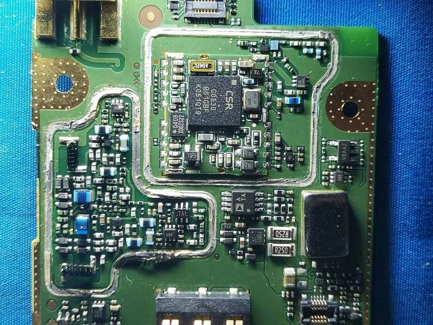
YAMHP6XXUMS
Jul 22, 2021Digital Portable Radio
Equipment Class
DTS - Digital Transmission System