YBR-FB-2Wireless Water Detector Sensor
GreenField Direct, LCC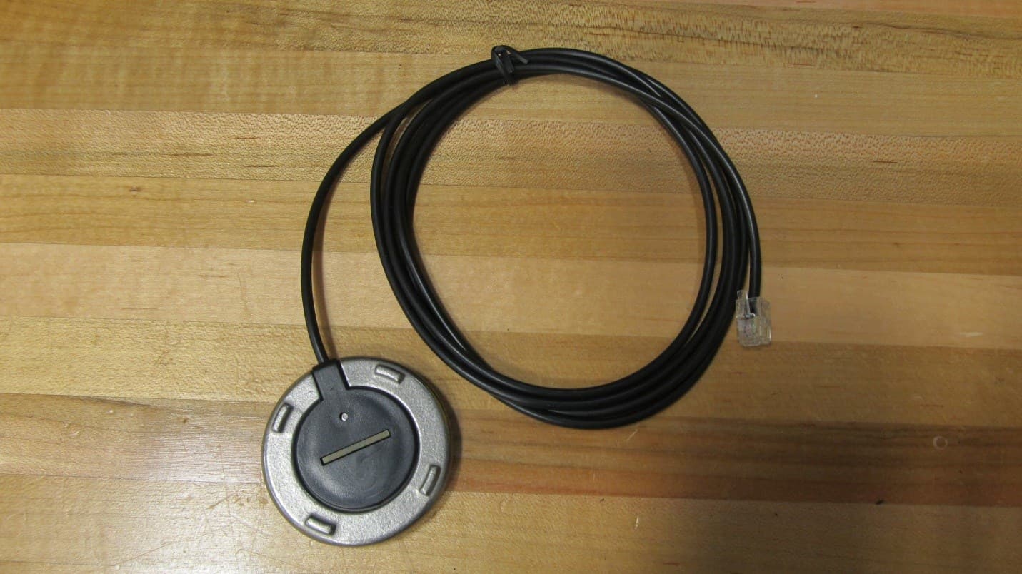
Click to zoom
Application Details
- Equipment Class
- DSR - Part 15 Remote Control/Security Device Transceiver
- Date of Grant
- Oct 18, 2011
- Application Purpose
- Original Equipment
- Date of Application
- Oct 04, 2011
- Equipment Note
- Wireless Water Detector Sensor
- Frequency Range
- 433.92000000 - 433.92000000
- Company
- GreenField Direct, LCC
- Country
- United States
Documents & Files
Document Text
Text extracted from the exhibit documents filed with the FCC. Open a document above to read the original.
Users Manual
GF1082 V1.9 www.PipeBurstPro.com 800-246-LEAK (5325) Installation and User’s Manual 2 | P a g e Congratulations on the purchase of your new PipeBurst Pro Automatic Water Protection System! Please visit www.PipeBurstPro.com for new components, features, tips and tricks and troubleshooting information. Table of Contents Installation .......................................................................................................................3 1. Tool Requirements ...................................................................................................3 2. Instructions ...............................................................................................................3 Setup and Operation .....................................................................................................4 3. Valve Interface Panel (VIP) .......................................................................................4 3.1. Component Description ..............................................................................................4 3.2. Button Function ..........................................................................................................5 3.3. System Condition .......................................................................................................6 3.4. Security System Interface ...........................................................................................6 4. FloodBug with SideKick ...........................................................................................8 4.1. Component Description ..............................................................................................8 4.2. Placement ...................................................................................................................8 4.3. Setup .......................................................................................................................9 5. FloTrax..................................................................................................................... 11 5.1. Component Description ............................................................................................ 11 5.2. Mounting ................................................................................................................... 12 5.3. Syncing the FloTrax .................................................................................................. 12 5.4. Monitor Mode ............................................................................................................ 12 5.5. TickerValve Operation .............................................................................................. 13 5.6. Program Mode .......................................................................................................... 13 5.7. Programming the FloTrax ......................................................................................... 14 6. Optional Base Hardwire Kit & Wiring Center ....................................................... 17 6.1. Component Description ............................................................................................ 17 6.2. Installation ................................................................................................................ 17 7. VIP Multiple Installation ......................................................................................... 18 7.1. Component Description ............................................................................................ 18 7.2. Installation ................................................................................................................ 18 8. Cleaning and Maintenance .................................................................................... 19 Troubleshooting ........................................................................................................... 20 1. What To Do When Water Is Detected ...................................................................... 20 2. Valve Interface Panel (VIP) ...................................................................................... 20 3 | P a g e Installation 1. Tool Requirements Note: These tool requirements assume the TickerValve is already installed by a licensed plumber. 1.1. Electric drill, drill bits, and screwdriver tips to mount the VIP and FloTrax to your wall as desired. 1.2. Philips #1 or #2 hand screw driver for final hand tightening. 1.3. Small (1/8” wide blade) screwdriver for wire installation into the terminal blocks. 2. Instructions 2.1. EXTREMELY IMPORTANT: INSTALL TICKERVALVE AFTER ALL FIRE SUPPRESSION LINES THAT MAY BE IN PLACE FOR THE FACILITY. 2.2. Use a licensed plumber to install the 1” stainless steel TickerValve in the facilities’ inlet water line(s). Proper placement of the valve is extremely important to fully protect the facility from fire and water damage. 2.3. Position the Valve Interface Panel (VIP). a. Verify that the TickerValve wires, SideKick, and the AC adapter will reach the VIP, floor, and AC outlet respectively. b. For best performance keep the VIP antenna 10 inches away from metal. 2.4. Hold the VIP to the wall and mark the 2 mounting holes on wall, then attach the VIP to wall with proper mounting hardware (not included). 2.5. Remove front cover from VIP and allow it to hang via its actuator cable. 2.6. TickerValve, Freeze Relief Valve & VIP wire designation: a. Terminal 1 Motor + Red Wire b. Terminal 2 Motor - Black Wire c. Terminal 3 Open Blue Wire d. Terminal 4 Closed Green Wire e. Terminal 5 Sense White Wire 2.7. Plug battery backup into 4 pin jack inside VIP, labeled “12V BATT” and set battery inside VIP. 2.8. The FCC label is located on the inside lower surface of the VIP case, visible during the AC power and battery backup installation. 2.9. Plug in AC adapter to standard 120VAC outlet. 2.10. The basic system is now installed, and the TickerValve can be control…
Text truncated - open the document above for the full version.
External Photos
GreenField Direct, LLC FCC ID: YBR-FB-2 External Photos: FloodBug IC: 8924A-FB100 GreenField Direct, LLC FCC ID: YBR-FB-2 External Photos: FloodBug IC: 8924A-FB100 GreenField Direct, LLC FCC ID: YBR-FB-2 External Photos: FloodBug IC: 8924A-FB100 GreenField Direct, LLC FCC ID: YBR-FB-2 External Photos: FloodBug IC: 8924A-FB100
ID Label/Location Info
FCC Label Placement – Valve Interface Panel and FloodBug GreenField Direct, LLC 10/4/11 FloodBug – GF9001 As the water detection device the FloodBug has the potential to be exposed to water, in order to help protect the label from water damage it is placed in the battery compartment. The Installation and User’s Manual instructs the user to open the battery compartment to install the batteries to power the FloodBug or remove the batteries if the FloodBug is powered by the AC adapter. The removal of the unused batteries is to prevent corrosion and damage to the FloodBug. Either startup option requires the user to open the battery compartment and reveal the FCC label. The FloodBug section of the PipeBurst Pro Installation and User’s Manual includes the text, “To prevent corrosion and damage to the FloodBug remove the batteries if the FloodBug is operated on AC power” and “The FCC Label is located inside the battery compartment, visible during the installation and removal of the batteries” to notify the user of its existence and location. Figure 1 ‐ FloodBug bottom side with battery cover removed, batteries installed, and visible FCC ID label Figure 2 ‐ FloodBug bottom side with AC plug attached, battery cover and batteries removed, and visible FCC ID label Figure 3 ‐ FloodBug FCC ID label location, up close
Internal Photos
GreenField Direct, LLC FCC ID: YBR-FB-2 Internal Photos: FloodBug IC: 8924A-FB100 GreenField Direct, LLC FCC ID: YBR-FB-2 Internal Photos: FloodBug IC: 8924A-FB100 GreenField Direct, LLC FCC ID: YBR-FB-2 Internal Photos: FloodBug IC: 8924A-FB100
Test Report
Nebraska Center for Excellence in Electronics 4740 Discovery Drive Lincoln, NE 68521-5376 Phone: 402.472.5880 Fax: 402.472.5881 Nebraska Center for Excellence in Electronics 4740 Discovery Drive Lincoln, NE 68521-5376 Phone: 402.472.5880 Fax: 402.472.5881 The Nebraska Center for Excellence in Electronics (NCEE) authorizes the above named company to reproduce this report provided it is reproduced in its entirety for use by the company’s employees only. Any use that a third party makes of this report, or any reliance on or decisions made based on it, are the responsibility of such third parties. NCEE accepts no responsibility for damages, if any, suffered by any third party as a result of decisions made or actions based on this report. This report applies only to the items tested. NCEE is a FCC and Industry Canada registered lab. FCC #100875, IC #4294 Test Report Company: Greenfield Direct, LLC 14015 238 th St. Greenwood, NE 68003 Contact: Scott Morgan Product: FloodBug FCC ID: YBR-FB-2 IC ID: 8924A-FB100 Test Report No: R081011-40E APPROVED BY: Nic Johnson _________________________ Test Engineer DATE: 19 October 2011 Total Pages: 26 NCEE Labs R081011-40E FCC ID:YBR-FB-2 IC ID:8924A-FB100 Page 2 of 27 1.0 Summary of test results 1.1 Test Results 1.2 Reason for Amendment 2.0 Description 2.1 Equipment under test 2.2 Laboratory description 2.3 Description of test modes 2.4 Applied standards 2.5 Configuration of system under test 3.0 Test equipment used 4.0 Detailed Results 4.1 15.207 Conducted Emissions 4.2 15.209, 15.231 Radiated emissions 4.3 15.231 Bandwidth Appendix A – Test photos Appendix B – Table of figures NCEE Labs R081011-40E FCC ID:YBR-FB-2 IC ID:8924A-FB100 Page 3 of 27 1.0 Summary of test results 1.1 Test Results The EUT has been tested according to the following specifications: APPLIED STANDARDS: 47 CFR Part 15 & RSS-210 Standard Section Test Type and Limit Result Remark 15.207 RSS-Gen Conducted AC Mains Emissions Pass Meets the requirement of the limit. 15.209, 15.231 RSS-Gen Radiated Emissions Peak Output Field Strength Limit: 80.83dBμV/m Pass Meets the requirement of the limit. 15.231 RSS-210 Issue 8 Bandwidth Pass Meets the requirement of the limit. 1.2 Reason for amendment. The Table from Section 1.1 was updated to list RSS-210 Issue 8. All testing was reviewed to ensure methods and results from previous testing were in accordance to the new standard. This report, R031510-01-01A is meant to amend and replace report R031510-01- 01. Amendment B: FCC ID Changed A RF duty cycle document was proided by KZCO. Calibration dates were corrected. The resolution bandwidth of conducted emissions measurements was added to Section 4.1.2. Amendment C: Changed contact to Scott Morgan Changed IC number back to 8924A-FB100 NCEE Labs R081011-40E FCC ID:YBR-FB-2 IC ID:8924A-FB100 Page 4 of 27 Amendment D: 1. Figure 5 showing the duty cycle has been put back in the report. The duty cycle correction factor has been correct to 20*log(85.577/100) = -1.35dB. All of the values in Table 4 were reduced by 0.30dB because the original duty cycle correction factor used was -1.05dB. All original test values were verified with original data to ensure that the values listed in the table are of the original field strength measurements and the -1.35dB correction factor. 2. For the 1 - 5GHz range, only peak measurements are shown, since they comply with the average limits. The noet under Table 5 has been modified to state this, and that the peak measurements are also compliant with the peak limit. 3. FCC Id is listed as YBR-FB-2. Contact is listed as Scott Morgan 4. Updated Theory of operation from KZCO has been put in report to replace old theory of operation. Amendment E: 1. The duty cycle correction factor was corrected using 88.577ms 2. The theory of operation was corrected. 2.0 Description 2.1 Equipment under test The FloodBug is a moisture detector which wirelessly transmits an alarm to a central valve controller (the VIP or Valve Interface Panel) to shut off water in a home or business. The FloodBug can operate either using battery or an external DC power supply. It can use a built-in water sensor or a remote water sensor, connected by a cable. The FloodBug is anticipated to be more often than not powered by two AA non- rechargeable alkaline cell batteries. The ground line on the battery will be disconnected, however, when a 5VDC power supply is plugged into the 2.1 MM power jack. The EUT is supplied with a 5VDC Tech Power Int. power supply, M/N TSA9-050120WU. EUT Received Date: 8/10/2011 EUT Tested Date: 8/10/2011 PRODUCT FloodBug SERIAL NUMBER Continuous transmit unit: 708 POWER SUPPLY 2 AA Batteries/5VDC power supply MODULATION TYPE FSK FREQUENCY RANGE 433.92MHz NUMBER OF CHANNELS 1 ANTENNA TYPE Internal dipole I/O PORTS 1 – External water sensor, Sidekick ASSOCIATED DEVICES FloTrax, V.I.P. Digital NCEE Labs R081011-40E FCC ID:YBR-FB-2 IC ID:8924A-FB100 Page 5 of 27 Figure 1 - EUT Photo, Normal Firmware NCEE Labs R081011-40E FCC ID:YBR-FB-2 IC ID:8924A-FB100 Page 6 of 27 Figure 2 - EUT Photo, Normal Firmware Figure 3 - EUT Photo, Normal Firmware NCEE Labs R081011-40E FCC ID:YBR-FB-2 IC ID:8924A-FB100 Page 7 of 27 FCC Label covered pending final design NOTE: 1. For more detailed features description, please refer to the manufacturer's specifications or User's Manual. 2.2 Laboratory description All testing was performed at the NCEE Lincoln facility, which is a FCC and IC registered lab. This site has been fully described in previously submitted reports. Laboratory environmental conditions varied slightly throughout the tests: Relative humidity of 45 ± 4% Temperature of 20 ± 3° Celsius NCEE Labs R081011-40E FCC ID:YBR-FB-2 IC ID:8924A-FB100 Page 8 of 27 2.3 Description of test modes The EUT was modified by the manufacturer to transmit continuously for testing purposes. It was set to transmit one packet after another with 20ms in between transmissions 2.4 Applied standards The EUT is a low-power transmi…
Text truncated - open the document above for the full version.
Test Setup Photos
NCEE Labs Test Photos FCC ID:YBR‐F B‐2 IC :8924A‐FB 100 Figure 1 ‐ Radiated Emissions Test Setup Figure 2 ‐ Radiated Emissions Test Setup NCEE Labs Test Photos FCC ID:YBR‐F B‐2 IC :8924A‐FB 100 Figure 3 ‐ Conducted Emissions Test Setup Figure 4 ‐ Conducted Emissions Test Setup
Contact Information
Applicant
Scott Morgan(CFO)
Technical Contact
GreenField Direct, LLCSteven Stock
[email protected]402-944-2767
14015 238th Street · Greenwood · United States
Test Firm
Nebraska Center for Excellence in ElectronicsNic Johnson
Technical Specifications
| # | Rule Parts | Frequency Range | Power Output |
|---|---|---|---|
| 1 | 15.231 | 433.92 MHz - 433.92 MHz | - |
Other Applications from GreenField Direct, LCC

YBR-FB100
Dec 27, 2010Automatic Water Protection System
Equipment Class
DSR - Part 15 Remote Control/Security Device Transceiver
YBR-VP100
Dec 27, 2010PipeBurst Pro
Equipment Class
DSR - Part 15 Remote Control/Security Device Transceiver
YBR-FT100
Jul 14, 2010PipeBurst Pro
Equipment Class
DSR - Part 15 Remote Control/Security Device Transceiver