YCH-IVACTPDust Collector Remote Control
BCTINT Limited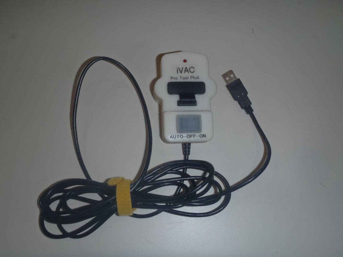
Click to zoom
Application Details
- Equipment Class
- DSC - Part 15 Security/Remote Control Transmitter
- Date of Grant
- Jun 16, 2014
- Application Purpose
- Original Equipment
- Date of Application
- Jun 16, 2014
- Equipment Note
- Dust Collector Remote Control
- Frequency Range
- 434.00600000 - 434.01500000
- Company
- BCTINT Limited
- Country
- Canada
Documents & Files
Document Text
Text extracted from the exhibit documents filed with the FCC. Open a document above to read the original.
Users Manual
iVAC Pro Tool Plus User Guide Rev 2 Date 28 May 2014 This User Guide is intended to cover the programming, setup and use of the ‘iVAC Pro Tool Plus’ (‘Tool Plus’). It also covers the General Description and Features of the ‘IVAC Pro System’. Table of Contents 1 Warnings. 2 General Description of ‘iVAC Pro System’ 3 ‘iVAC Pro Tool Plus’ 4 Physical Features 5 Modes of Operation 6 Program Switch 7 System Address 8 Multi Tool Operation 9 Tool Address 10 Active Current sense level 11 Sensitivity Adjustment. 12 System Test 13 ‘Tool Plus’ Features 14 Specifications. 15 Regulatory Compliance 16 Warranty 17 Contact 1. Warnings Please read the operating instructions before use. The ‘Tool Plus’ is intended for indoor use, in dry locations only. The ‘Tool Plus’ is powered from an AC to DC 5V USB adapter The USB Adapter should only be connected to AC mains circuits at the rated voltage. 2. General Description of ‘iVAC Pro System’ The ‘iVAC Pro System’ consists of two groups of product. The first group consists of units that transmit information and a second group of units that receive the transmitted information. At the present time the first group that transmit information are the ‘iVAC Pro Remote’ and three versions of the ‘iVAC Pro Tool’ units. The ‘iVAC Pro Tool Plus’, the ‘iVAC Pro Tool’, and the ‘iVAC Pro Tool HP’. The ‘Tool’ units. The units that receive the information are the ‘iVAC Pro Switch’ which controls the Dust Collector and the ‘iVAC Pro Blast Gate’. The ‘Tool’ units monitor the status of its associated power tool. When the power tool turns on it sends a digital wireless signal instructing the ‘iVAC Pro Switch’ to turn on the Dust Collector and the ‘iVAC Pro Blast Gate’ to open. .The following discussions relate to communications with an ‘iVAC Pro Switch’ although the same actions/response apply to the ‘iVAC Pro Blast Gate’. This User Guide will focus on the ‘Tool Plus’. 3 ‘iVAC Pro Tool Plus’ (‘Tool Plus’) The ‘Tool Plus’ unit is used to identify the powered on state of its associated power tool. The ‘Tool Plus’ is physically clamped to the power cord of the power tool. The method of detecting the status of the power tool is by means of sensing the magnetic field around the power cord when the power tool is turned on or off. The ‘Tool Plus’ is powered by +5VDC. This power is obtained from either a UL FCC approved AC to DC 5volt USB adaptor, or an associated ‘iVAC Pro System’ unit. If a ‘Tool Plus’ unit is in the Auto Mode when the associated power tool is powered on, the ‘Tool Plus’ unit will transmit an instruction, by means of a digital wireless signal, to the ‘iVAC Pro Switch’ instructing it to turn on and apply power to the Dust Collector. When the power tool has been turned off, the ‘Tool Plus’ units will transmit an instruction to the ‘iVAC Pro Switch’ telling it to turn off. The range for radio communications between the ‘Tool Plus’ and the ‘iVAC Pro Switch’ is forty feet. When mounting the ‘iVAC Pro units’ they should not be mounted on large metal objects, since this can affect the communication range. 4. Physical Features 5 Modes of Operation The ‘Tool Plus’ has three modes of operation; AUTO – OFF – ON, as set by the Mode Switch. In the AUTO mode the ‘Tool Plus’ transmits information to an ‘iVAC Pro Switch’ each time the connected power tool is turned on or off. When in AUTO Mode the ‘Tool Plus’ senses the current in the power cable of the power tool it is attached to. If the power tool is ON, the LED will be ON, and the LED will be OFF if the power tool is OFF When the power tool turns ON or OFF the led will flash for about 3 seconds indicating it is transmitting the appropriate ON or OFF command As the Mode Switch is transferred from AUTO to OFF, a transmission is sent to the ‘iVAC Pro Switch’, instructing it to turn off. The LED will flash during the RF transmission As the Mode Switch is moved from OFF to ON, a transmission is sent to the ‘iVAC Pro Switch’, instructing it to turn on. The LED will flash during the RF transmission. As the Mode Switch is transferred from ON to OFF, a transmission is sent to the ‘iVAC Pro Switch’, instructing it to turn off. The LED will flash during the RF transmission. As the Mode Switch is moved from OFF to AUTO, a transmission is sent to the ‘iVAC Pro Switch’. The command sent will be an ON command IF the power tool is ON or an OFF command if the power tool is OFF.. The LED will flash during the RF transmission. CAUTION: It is important to NOT change the Mode Switch while the ‘Tool Plus’ is transmitting. You must wait until the LED stops flashing before moving the Mode Switch from Auto to OFF, OFF to ON, ON to OFF or OFF to AUTO. NOTE When in OFF or ON Mode the LED indicates how much current is flowing to the power tool. This indication is dependent on the setting of the Sensitivity control. Once the Sensitivity of the ‘Tool Plus’ has been properly set up, see section 11 below, LED = Off Power tool is Off LED Flashing The LED has two flash rates, both rates are faster than the flash rate when the ‘Tool Plus’ is transmitting RF commands. LED = ON Power tool is On 6 Program Switch The Program Switch is accessed through the Program Switch Cover located in the top surface of the unit. It enables the programming of the System Address and the Tool Address. Changes to the Program Switch must be performed with the Mode Switch in the OFF position. Changes to the Program switch with the Mode switch in AUTO mode will be ignored. 7 System Address A System consists of up to eight ‘Tool Plus’ units that can control one ‘iVAC Pro Switch’ By means of the Program Switch, the ‘Tool Plus’ can be assigned to work on one of four System Addresses, A, B, C or D. The System Address is to enable up to four systems to operate independently while within communication range of each other. All units required to operate as a System must be set to the same System Address. System Address S1 S2 A * off off B on off C off on D on on * factory setting 8 Multi Tool Operati…
Text truncated - open the document above for the full version.
Test Report
REGISTRATION #6844B-1 REG#382292 Testing Laboratory Certificate #2555.01 Page 1 of 68 Report issue date: 6/12/2014 GEMC-FCC-Q50083 R2 © Global EMC Inc. This test report shall not be reproduced except in full, without written approval of Global EMC Inc. This report is based on GEMC Template “FCC 15 231 Rev1.” Global EMC Inc. Labs EMC & RF Test Report As per RSS 210 Issue 8:2010 & FCC Part 15 Subpart C:2013 Unlicensed Intentional Radiators on the iVAC Pro Tool Plus Yong Huang Project Specialist Global EMC Inc. Laval 2972 Joseph-A-Bombardier Laval, QC, H7P 6E3 CANADA Ph: (450) 687- 4976 Testing produced for See Appendix A for full customer & EUT details. Client BCTINT Ltd. Product iVAC Pro Tool Plus Standard(s) RSS 210 Issue 8:2010 / FCC Part 15 Subpart C 15:2013 Page 2 of 68 Report issue date: 6/12/2014 GEMC File #: GEMC-FCC-Q50083R2 © Global EMC Inc. This test report shall not be reproduced except in full, without written approval of Global EMC Inc. Table of Contents Table of Contents ................................................................................................................... 2 Report Scope .......................................................................................................................... 3 Summary ................................................................................................................................ 4 Test Results Summary ....................................................................................................... 5 Justifications, Descriptions, or Deviations......................................................................... 7 Applicable Standards, Specifications and Methods ........................................................... 9 Sample calculation(s) ....................................................................................................... 10 Document Revision Status ............................................................................................... 10 Definitions and Acronyms ................................................................................................... 11 Testing Facility .................................................................................................................... 12 Calibrations and Accreditations ....................................................................................... 12 Testing Environmental Conditions and Dates ................................................................. 13 Detailed Test Results Section .............................................................................................. 14 Radiated Emissions .......................................................................................................... 15 20 dB Bandwidth of Periodically Operated Transmitters ................................................ 28 Radiated Emissions of Fundamental ................................................................................ 31 Radiated Emissions of Spurious Emissions ..................................................................... 38 Power Line Conducted Emissions ................................................................................... 51 Appendix A – EUT Summary .............................................................................................. 60 Appendix B – EUT and Test Setup Photographs................................................................. 62 Client BCTINT Ltd. Product iVAC Pro Tool Plus Standard(s) RSS 210 Issue 8:2010 / FCC Part 15 Subpart C 15:2013 Page 3 of 68 Report issue date: 6/12/2014 GEMC File #: GEMC-FCC-Q50083R2 © Global EMC Inc. This test report shall not be reproduced except in full, without written approval of Global EMC Inc. Report Scope This report addresses the EMC verification testing and test results of the iVAC Pro Tool Plus, herein referred to as EUT (Equipment Under Test) performed at Global EMC Labs. The EUT was tested for compliance against the following standards: RSS 210 Issue 8:2010 / FCC Part 15 Subpart C 15:2013 Test procedures, results, justifications, and engineering considerations, if any, follow later in this report. The results contained in this report relate only to the item(s) tested. This report does not imply product endorsement by A2LA or any other accreditation agency, any government, or Global EMC Inc. Opinions/interpretations expressed in this report, if any, are outside the scope of Global EMC Inc accreditation. Any opinions expressed do not necessarily reflect the opinions of Global EMC Inc, unless otherwise stated. Client BCTINT Ltd. Product iVAC Pro Tool Plus Standard(s) RSS 210 Issue 8:2010 / FCC Part 15 Subpart C 15:2013 Page 4 of 68 Report issue date: 6/12/2014 GEMC File #: GEMC-FCC-Q50083R2 © Global EMC Inc. This test report shall not be reproduced except in full, without written approval of Global EMC Inc. Summary The results contained in this report relate only to the item(s) tested. EUT FCC Certification #, FCC ID: YCH-IVACTP EUT Industry Canada Certification #, IC: 8940A-IVACTP EUT Passed all tests performed. Yes (see test results summary) Tests conducted by Yong Huang Client BCTINT Ltd. Product iVAC Pro Tool Plus Standard(s) RSS 210 Issue 8:2010 / FCC Part 15 Subpart C 15:2013 Page 5 of 68 Report issue date: 6/12/2014 GEMC File #: GEMC-FCC-Q50083R2 © Global EMC Inc. This test report shall not be reproduced except in full, without written approval of Global EMC Inc. Test Results Summary Table 1 – Manual Operation Standard/Method Description Class/Limit Result FCC 15.203 Antenna Requirement Unique Pass See Justification FCC 15.205 RSS 210 (Table 1) Restricted Bands for intentional operation QuasiPeak Average Pass FCC 15.207 Power line conducted emissions QuasiPeak Average Pass FCC 15.209 RSS-210 (Table 2) FCC 15.231(b) RSS-210 (Table 4) Intentional / Spurious Radiated emissions QuasiPeak Average Pass FCC 15.231(a) RSS-210 A1.1 Type of transmission Not a continuous transmissions, voice, vid…
Text truncated - open the document above for the full version.
Test Setup Photos
Client BCTINT Ltd. Product iVAC Pro Tool Plus Standard(s) RSS 210 Issue 8:2010 / FCC Part 15 Subpart C 15:2013 Page 63 of 68 Report issue date: 6/11/2014 GEMC File #: GEMC-FCC-Q50083R2 © Global EMC Inc. This test report shall not be reproduced except in full, without written approval of Global EMC Inc. EUT’s Photo Client BCTINT Ltd. Product iVAC Pro Tool Plus Standard(s) RSS 210 Issue 8:2010 / FCC Part 15 Subpart C 15:2013 Page 64 of 68 Report issue date: 6/11/2014 GEMC File #: GEMC-FCC-Q50083R2 © Global EMC Inc. This test report shall not be reproduced except in full, without written approval of Global EMC Inc. Radiated Emission Test Setup Photo #1: Client BCTINT Ltd. Product iVAC Pro Tool Plus Standard(s) RSS 210 Issue 8:2010 / FCC Part 15 Subpart C 15:2013 Page 65 of 68 Report issue date: 6/11/2014 GEMC File #: GEMC-FCC-Q50083R2 © Global EMC Inc. This test report shall not be reproduced except in full, without written approval of Global EMC Inc. Radiated Emission Test Setup Photo #2: Client BCTINT Ltd. Product iVAC Pro Tool Plus Standard(s) RSS 210 Issue 8:2010 / FCC Part 15 Subpart C 15:2013 Page 66 of 68 Report issue date: 6/11/2014 GEMC File #: GEMC-FCC-Q50083R2 © Global EMC Inc. This test report shall not be reproduced except in full, without written approval of Global EMC Inc. Radiated Emission Test Setup Photo #3: Client BCTINT Ltd. Product iVAC Pro Tool Plus Standard(s) RSS 210 Issue 8:2010 / FCC Part 15 Subpart C 15:2013 Page 67 of 68 Report issue date: 6/11/2014 GEMC File #: GEMC-FCC-Q50083R2 © Global EMC Inc. This test report shall not be reproduced except in full, without written approval of Global EMC Inc. Conducted Emission Test Setup Photo#1: Client BCTINT Ltd. Product iVAC Pro Tool Plus Standard(s) RSS 210 Issue 8:2010 / FCC Part 15 Subpart C 15:2013 Page 68 of 68 Report issue date: 6/11/2014 GEMC File #: GEMC-FCC-Q50083R2 © Global EMC Inc. This test report shall not be reproduced except in full, without written approval of Global EMC Inc. Conducted Emission Test Setup Photo#2:
Contact Information
Applicant
Jack Lynn(General Manager)
Test Firm
Global EMC Inc.Scott Drysdale
[email protected]4506874976
Technical Specifications
| # | Rule Parts | Frequency Range | Power Output |
|---|---|---|---|
| 1 | 15.231 | 434.006 MHz - 434.015 MHz | - |
Other Applications from BCTINT Limited
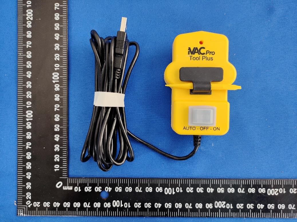
YCH-IVACTPG
Jun 08, 2022TOOL PLUS
Equipment Class
DXX - Part 15 Low Power Communication Device Transmitter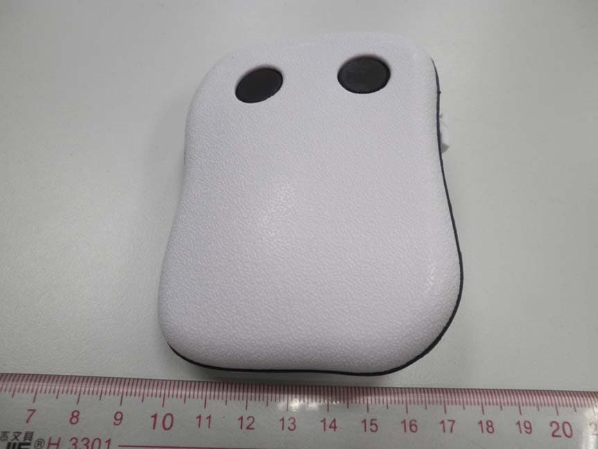
YCHIVACPRO
May 04, 2011iVAC pro Remote
Equipment Class
DSC - Part 15 Security/Remote Control Transmitter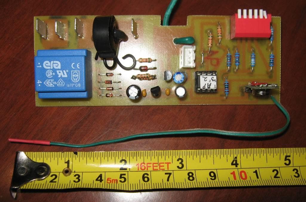
YCHIVACRFM
Sep 08, 2010MODULE USED IN AUTOMATED DUST COLLECTION CONTROL UNIT
Equipment Class
DSC - Part 15 Security/Remote Control Transmitter