YCHIVACRFMMODULE USED IN AUTOMATED DUST COLLECTION CONTROL UNIT
BCTINT Limited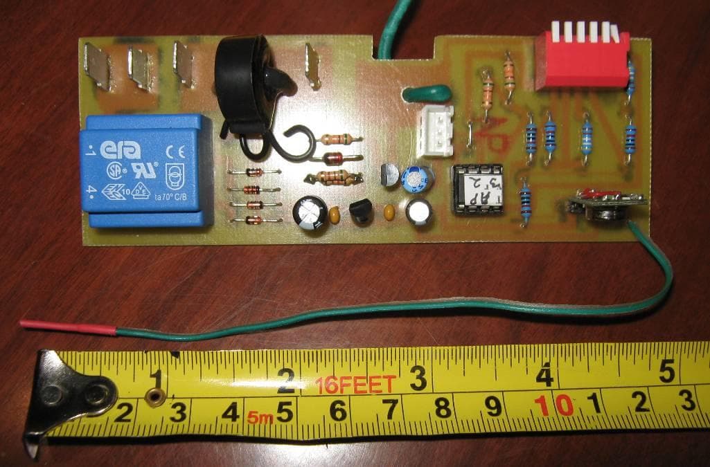
Click to zoom
Application Details
- Equipment Class
- DSC - Part 15 Security/Remote Control Transmitter
- Date of Grant
- Sep 08, 2010
- Application Purpose
- Original Equipment
- Date of Application
- Sep 07, 2010
- Equipment Note
- MODULE USED IN AUTOMATED DUST COLLECTION CONTROL UNIT
- Frequency Range
- 433.92000000 - 433.92000000
- Company
- BCTINT Limited
- Country
- Canada
Documents & Files
Document Text
Text extracted from the exhibit documents filed with the FCC. Open a document above to read the original.
Users Manual
SYSTEM USER GUIDE Pro MBright Tools In c. Pro.com www. SWITCH 103 84- 000 0 240 V, 16A # S 24020 NA by MB righ t Tool s Inc. ww w.i VACPro.com AUTO / OF F / ON Pr o iVAC Pro TOOL iVAC Pro SWITCH Introduction This User Guide covers the General Description, Features and Programming of the “IVAC Pro System”. The iVAC Pro System consists of two basic items, the iVAC Pro Tool and the iVAC Pro Switch. It is recommended that you first read General sections 1, 2 and 3 and then focus on your most recent purchase, either the iVAC Pro Tool, Section 4, or the iVAC Pro Switch, section 5. Table of Contents 1 Warnings. 2 Physical features 3 General description of ‘iVAC Pro System’ 4 ‘iVAC Pro Tool’ 4.1 Modes of Operation 4.2 Program Switch 4.3 System Address 4.4 Multi Tool Operation 4.5 Tool Address 4.6 Active current sense level 4.7 ‘iVAC Pro Tool’ Specifications 5 ‘iVAC Pro Switch’ 5.1 Modes of Operation 5.2 System Address 5.3 Turn On Delay 5.4 Turn Off Time 5.5 Master Reset 5.6 ‘iVAC Pro Switch’ Specifications 6 System Set Up 6.1 Location 6.2 Setting System Address 6.3 Setting Tool Address 6.4 Setting Turn Off Time 7 Warranty Contact Table of Contents (conitued) 1. Warnings Please read the operating instructions before use. The ‘iVAC Pro System’ is intended for indoor use, in dry locations only. The ‘iVAC Pro Tool’ and ‘iVAC Pro Switch’ should only be connected to AC mains circuits at the rated voltage and current. The AC Mains receptacle should have ease of access in the event that quick disconnection is required. 2. Physical Features AC receptacle Product Label Mode switch Circuit breakers AC power cord Approval labels Program Switch Program Switch cover Program labels 3. General Description of ‘iVAC Pro System’ The ‘iVAC Pro System’ consists of two families of product, the ‘iVAC Pro Tool’ unit and the ‘iVAC Pro Switch’ unit. A work shop system may consist of up to eight ‘iVAC Pro Tool’ units and at least one ‘iVAC Pro Switch’ unit. The ‘iVAC Pro Tool’ unit is connected to the AC mains supply by means of its power cord and then to a workshop tool through its AC receptacle. If an ‘iVAC Pro Tool’ unit is in the Auto mode when a power tool that is connected to it is powered on, the ‘iVAC Pro Tool’ unit will transmit, by means of a wireless signal, to the ‘iVAC Pro Switch’ instructing it to turn on. The ‘iVAC Pro Switch’ unit is connected to the AC mains supply by means of its power cord and then to a workshop dust collection system through its AC receptacle. When the ‘iVAC Pro Switch’ receives a signal from the ‘iVAC Pro Tool’ instructing it to turn on, it will supply power to the dust collection system. After the power tool has been turned off, the ‘iVAC Pro Switch’ will continue to provide power to the dust collection system for the Turn Off Time. The Turn Off Time is programmable by means of the Program Switch. The range for radio communications between the ‘iVAC Pro Tool’ and the ‘iVAC Pro Switch’ is forty feet, line of sight. When mounting the ‘iVAC Pro units’ they should not be mounted on large metal objects, since this can affect the communication range. Both the ‘iVAC Pro Tool’ and the ‘iVAC Pro Switch’ have a series of programmable features that are set by means of the Program Switch. The Program Switch is accessible through the small removable cover in the base. There are four variants of both the ‘iVAC Pro Tool’ TxxxyyNA and ‘iVAC Pro Switch’ SxxxyyNA in order to accommodate the various power requirements of power tools and dust collection systems. xxx identifies the rated AC mains voltage, which is either 115 or 240Vac. yy identifies the current rating of the units associated circuit breakers, which is either 15 or 20 Amps. VariantiVAC Pro SwitchiVAC Pro Tool 115Vac 15AmpS11515NAT11515NA 115Vac 20AmpS11520NAT11520NA 240Vac 15AmpS24015NAT24015NA 240Vac 20AmpS24020NAT24020NA 4. ‘iVAC Pro Tool’ The ‘iVAC Pro Tool’ is connected in series between the AC mains power and an associated power tool. ‘The iVAC Pro Tool’ operates in conjunction with an ‘iVAC Pro Switch’ which in turn controls a dust collection system. 4.1 Modes of Operation The ‘iVAC Pro Tool’ has three modes of operation; Auto – Off – On, as set by the Mode Switch. In the Auto mode the ‘iVAC Pro Tool’ transmits information to an ‘iVAC Pro Switch’ each time the connected power tool is turned on or off. As the Mode Switch is transferred from Off to On, a transmission is sent to the ‘iVAC Pro Switch’, instructing it to turn on. As the Mode Switch is transferred from On to Off, a transmission is sent to the ‘iVAC Pro Switch’, instructing it to turn off. 4.2 Program Switch The Program Switch is accessed through the Program Switch cover located in the base of the unit. It enables the programming of the System Address and the Tool Address. 4.3 System Address A System consists of an ‘iVAC Pro Switch’ and up to eight ‘iVAC Pro Tools’ that are intended to work together. By means of the Program Switch, the ‘iVAC Pro Tool’ can be assigned to work on one of four System Addresses, A, B, C or D. The System Address is to enable up to four systems to operate independently while within communication range of each other. All units required to operate as a system must be set to the same System Address. 4.4 Multi Tool Operation The ‘iVAC Pro’ system has been designed so that up to eight ‘iVAC Pro Tools’ can communicate with one ‘iVAC Pro Switch’ on the same System Address. Several ‘iVAC Pro Tools’ can be in operation at the same time. The first ‘iVAC Pro Tool’ to turn on, will turn on the ‘iVAC Pro Switch’. The last tool to turn off, will turn off the ‘iVAC Pro Switch’. System Address S1S2 AOffOff BOnOff COffOn DOnOn System Address Programming. All switches shown in Off position. 4.5 Tool Address Each ‘iVAC Pro Tool’ must be assigned an independent one of eight tool address. This information is presently used by the ‘iVAC Pro Switch’ to enable it to know the status of each individual tool in a system. The Tool Address is set by means of the Program Swit…
Text truncated - open the document above for the full version.
Cover Letter(s)
The MBright Group Inc. P.O. Box 557, 5570 Jill Street Osgood, Ontario Canada K0A 2W0 Tel 613.826.2200 Fax 613.826.3300 www.TheMBrightGroup.com [email protected] “Doing It Right, With MBright” September 2, 2010 Federal Communications Commission Authorization and Evaluation Division Confidentiality Request regarding application for certification of FCC ID: YCH-IVACRFM Pursuant to Sections 0.457 and 0.459 of the Commission’s Rules, we hereby request confidential treatment of information accompanying this application as outlined below: Exhibit Type File Name Schematics CONF IVAC RF MODULE SCHEM Parts List CONF IVAC RF MODULE PARTSLST Block diagrams Operational Description CONF IVAC RF MODULE BLKDIA CONF iVAC RF MODULE OPDES The above materials contain trade secrets and proprietary information not customarily released to the public. The public disclosure of these materials may be harmful to the applicant and provide unjustified benefits to its competitors. The applicant understands that pursuant to Section 0.457 of the Rules, disclosure of this application and all accompanying documentation will not be made before the date of the Grant for this application. Sincerely, Leon Brown President and C.F.O. MBright Tools IVAC Inc.
Cover Letter(s)
MBright Tools IVAC Inc. 5570 Jill Street, P.O. Box 557 Osgoode, Ontario, Canada, K0A 2W0 www.iVacSwitch.com Tel: (613) 826-2200 I Fax: (866) 255-6506 I Toll Free: (888) 273-5742 ext. 101 Dear Industry Canada / FCB and FCC / TCB representative, We request “Limited Modular Approval” (LMA) for our proprietary 433 MHz wireless switching module, which will be installed exclusively by us, the Grantee, in products which we will design and manufacture. This device is a complete RF transmitter, i.e., it has its own reference oscillator (e.g., VCO), antenna, etc. The only connectors to the module, are power supply and activation (Auto/Off/On) switch. Compliance with Industry Canada Safety Code 6 RF Exposure requirements and FCC RF Exposure requirements is passing and is calculated in accordance with the test report, with sufficient margin. We are aware that the end device into which an authorized module is installed is not required to obtain a new authorization for the module, however this does not preclude the possibility that some other form of authorization or testing may be required for the device (e.g., A unit in which an authorized module is installed must still meet conducted and radiated emission limits). The modular transmitter does not have its own RF shielding. However, the module does not rely upon the shielding provided by the device into which it is installed in order for all modular transmitter emissions to comply with Part 15 emissions limits. Coupling between the RF circuitry of the module and any wires or circuits in the device into which the module is installed that may result in non-compliant operation, will be verified on an end- product basis. The modular transmitter does not have buffered modulation/data inputs, since such input ports are not provided on the device. The input signal only serves to activate an on/off RF pulse, and will not encounter conditions of excessive data rates or over-modulation. The modular transmitter has its own power supply regulation. This ensures that the module will comply with Part 15 requirements regardless of the design of the power supplying circuitry in the device into which the module is installed. The modular transmitter complies with the antenna requirements of Section 15.203 and 15.204(c). The antenna is permanently mounted on the module. The antenna to be used with the module is included with the test report. Any additional antennas will result in a Class II permissive change. The module was tested inside the plastic enclosure of the final product, which does not provide any shielding properties, therefore the module can be considered to be tested in the stand-alone configuration. This shows that the module is capable of complying with Part 15 emission limits regardless of the device into which it is eventually installed. The transmitter module complies with the AC line conducted requirements found in 15.207. The power lines and data lines connected to the module do not contain ferrites which will not be marketed with the product. The lengths of these lines are typical of actual use in the product. No accessories, peripherals, or support equipment connected was required, as the modular transmitter can operate in a stand-alone condition. MBright Tools IVAC Inc. 5570 Jill Street, P.O. Box 557 Osgoode, Ontario, Canada, K0A 2W0 www.iVacSwitch.com Tel: (613) 826-2200 I Fax: (866) 255-6506 I Toll Free: (888) 273-5742 ext. 101 The modular transmitter will be labeled with its own IC/FCC ID number, and, if the IC/FCC ID is not visible when the module is installed inside another device, then the outside of the device into which the module is installed will also display a label referring to the enclosed module. This exterior label of such products will use wording such as the following: “Contains FCC ID: YCH-IVACRFM.” Included in our application is an example of this label. Internal documentation regarding the use of this module explains these requirements. As this module will be for use exclusively by the Grantee, we attest that we will retain control of this labeling and ensure this requirement is met on the end use product. The device is not a split modular transmitter. The modular transmitter complies with any applicable RF exposure requirements, as per the test report. The end device manual will provide specific installation and operating instructions for users, installers and other interested parties to ensure compliance, such as that „a minimum distance of 20cm between the antenna and any person is to be maintained during operation‟ under typical operating conditions. As the shielding requirement is not met, we request a limited modular approval. The modular device will be installed in the end product exclusively by the Grantee. We, the Grantee, attest that we will retain control over the installation of the device in the final product, such that compliance of the end product is assured. We attest that manufacturing procedures, policies, and training will be implemented for those involved in the production process to ensure compliance during installation in the end product. We recognize that an operating condition on the grant of equipment authorization for the module will state that the module is only approved for use when installed in devices produced by us, “MBright”, the Grantee. Control of the end product(s), into which the module will be installed, will be maintained by verification of the end product(s), such that full compliance of the end product is always ensured. I, the undersigned, attest that I am an authorized representative of MBright and attest to the above. _______________________ Leon Brown, CFO June 2, 2010
External Photos
EUT: Front surface EUT: Back surface
ID Label/Location Info
1234 ON 56 iVAC PRO RF Module Rev 1 - 10267 - 0400 FCC ID: YCH-iVACRFMFCC ID: YCH-IVACRFM 1 . 786 " 1.70" 2.30" 4.65" 0.190" 0.050" A B C D E 12345678 A B C D E 12345678 iVac Pro RF Module Rev 1 June 10, 2010 PCB p/n 10267-0400 Designed: GAN/BK Design CAD SW: Eagle NOTES: 2. PCB Material: 0.062" FR4 3. Green Solder mask 1. Single Side, 1oz. Copper 4. White Component silk screen 5. ROHS compatable finish 0.8128 mm / 32.000 mil 1.0000 mm / 39.370 mil 1.1000 mm / 43.307 mil 2.0000 mm / 78.740 mil 2.2000 mm / 86.614 mil 3.2000 mm / 125.984 mil Date: 5/13/2010 8:31:06 PM Drill legend
ID Label/Location Info
1234 ON 56 iVAC PRO RF Module Rev 1 - 10267 - 0400 FCC ID: YCH-iVACRFMFCC ID: YCH-IVACRFM 1 . 786 " 1.70" 2.30" 4.65" 0.190" 0.050" A B C D E 12345678 A B C D E 12345678 iVac Pro RF Module Rev 1 June 10, 2010 PCB p/n 10267-0400 Designed: GAN/BK Design CAD SW: Eagle NOTES: 2. PCB Material: 0.062" FR4 3. Green Solder mask 1. Single Side, 1oz. Copper 4. White Component silk screen 5. ROHS compatable finish 0.8128 mm / 32.000 mil 1.0000 mm / 39.370 mil 1.1000 mm / 43.307 mil 2.0000 mm / 78.740 mil 2.2000 mm / 86.614 mil 3.2000 mm / 125.984 mil Date: 5/13/2010 8:31:06 PM Drill legend
Internal Photos
EUT: Front surface EUT: Back surface
Test Report
Global EMC Inc. Labs EMC & RF Test Report As per RSS 210 Issue 7:2007 & FCC Part 15 Subpart C: 2008 Unlicensed Intentional Radiators on the iVAC RF Module Raymond Lee Au Project Engineer Global EMC Inc. 180 Brodie Drive, Unit 2 Richmond Hill, ON, L4B 3K8 Canada Ph: (905) 883-8189 Testing produced for See Appendix A for full customer & EUT details. LAB REGISTRATION #6844A-1 FCC REGISTRATION #612361 Page 1 of 57 Report issue date: 9/2/2010 GEMC File #: GEMC-FCC-19561R1 © Global EMC Inc. This test report shall not be reproduced except in full, without written approval of Global EMC Inc. This report is based on GEMC Template “FCC 15 231 Rev1.” Client MBright Tools IVAC Inc Product iVAC RF Module Standard(s) RSS 210 Issue 7:2007 / FCC Part 15 Subpart C 15:2008 Page 2 of 57 Report issue date: 9/2/2010 GEMC File #: GEMC-FCC-19561R1 © Global EMC Inc. This test report shall not be reproduced except in full, without written approval of Global EMC Inc. Table of Contents Table of Contents ................................................................................................................... 2 Report Scope .......................................................................................................................... 3 Summary ................................................................................................................................ 4 Test Results Summary ....................................................................................................... 5 Justifications, Descriptions, or Deviations......................................................................... 6 Applicable Standards, Specifications and Methods ........................................................... 7 Sample calculation(s) ......................................................................................................... 8 Document Revision Status ................................................................................................. 8 Definitions and Acronyms ..................................................................................................... 9 Testing Facility .................................................................................................................... 10 Calibrations and Accreditations ....................................................................................... 10 Testing Environmental Conditions and Dates ................................................................. 11 Detailed Test Results Section .............................................................................................. 12 Radiated Emissions .......................................................................................................... 13 20 dB Bandwidth of Periodically Operated Transmitters ................................................ 24 Radiated Emissions of Fundamental ................................................................................ 27 Radiated Emissions of Spurious Emissions ..................................................................... 33 Power Line Conducted Emissions ................................................................................... 44 Appendix A – EUT Summary.............................................................................................. 51 Appendix B – EUT and Test Setup Photographs................................................................. 53 Client MBright Tools IVAC Inc Product iVAC RF Module Standard(s) RSS 210 Issue 7:2007 / FCC Part 15 Subpart C 15:2008 Page 3 of 57 Report issue date: 9/2/2010 GEMC File #: GEMC-FCC-19561R1 © Global EMC Inc. This test report shall not be reproduced except in full, without written approval of Global EMC Inc. Report Scope This report addresses the EMC verification testing and test results of the iVAC RF Module, herein referred to as EUT (Equipment Under Test) performed at Global EMC Labs. The EUT was tested for compliance against the following standards: RSS 210 Issue 7:2007 / FCC Part 15 Subpart C 15:2008 Test procedures, results, justifications, and engineering considerations, if any, follow later in this report. The results contained in this report relate only to the item(s) tested. This report does not imply product endorsement by A2LA or any other accreditation agency, any government, or Global EMC Inc. Opinions/interpretations expressed in this report, if any, are outside the scope of Global EMC Inc accreditation. Any opinions expressed do not necessarily reflect the opinions of Global EMC Inc, unless otherwise stated. Client MBright Tools IVAC Inc Product iVAC RF Module Standard(s) RSS 210 Issue 7:2007 / FCC Part 15 Subpart C 15:2008 Page 4 of 57 Report issue date: 9/2/2010 GEMC File #: GEMC-FCC-19561R1 © Global EMC Inc. This test report shall not be reproduced except in full, without written approval of Global EMC Inc. Summary The results contained in this report relate only to the item(s) tested. EUT FCC Certification #, FCC ID: YCH-IVACRFM EUT Industry Canada Certification #, IC: 8940A-IVACRFM EUT Passed all tests performed. Yes (see test results summary) Tests conducted by Raymond Lee Au Client MBright Tools IVAC Inc Product iVAC RF Module Standard(s) RSS 210 Issue 7:2007 / FCC Part 15 Subpart C 15:2008 Page 5 of 57 Report issue date: 9/2/2010 GEMC File #: GEMC-FCC-19561R1 © Global EMC Inc. This test report shall not be reproduced except in full, without written approval of Global EMC Inc. Test Results Summary Table 1 – Manual Operation Standard/Method Description Class/Limit Result FCC 15.203 Antenna Requirement Unique Pass See Justification FCC 15.205 RSS 210 (Table 1) Restricted Bands for intentional operation QuasiPeak Average Pass FCC 15.207 Power line conducted emissions QuasiPeak Average Pass FCC 15.209 RSS-210 (Table 2) FCC 15.231(b) RSS-210 (Table 4) Intentional / Spurious Radiated emissions QuasiPeak Average Pass FCC 15.231(a) RSS-210 A1.1 Type of transmission Not a continuous transmissions…
Text truncated - open the document above for the full version.
Test Setup Photos
Radiated emissions testing (EUT tested in plastic enclosure) Conducted emissions testing (EUT tested in plastic enclosure, with resistive load connected)
Contact Information
Applicant
Jack Lynn(General Manager)
Test Firm
Global EMC Inc.Scott Drysdale
Technical Specifications
| # | Rule Parts | Frequency Range | Power Output |
|---|---|---|---|
| 1 | 15.231 | 433.92 MHz - 433.92 MHz | 1.00 mW |
Other Applications from BCTINT Limited
YCH-IVACTPG
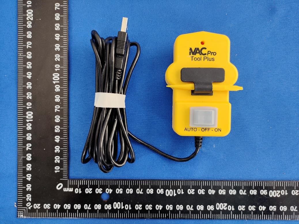
Jun 08, 2022TOOL PLUS
Equipment Class
DXX - Part 15 Low Power Communication Device Transmitter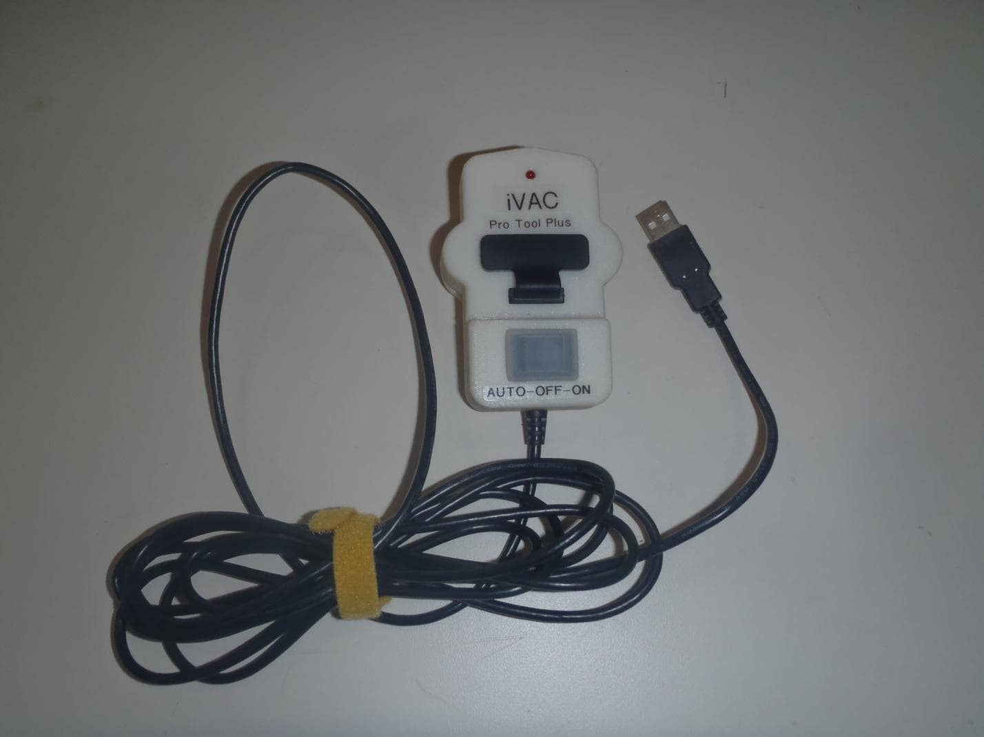
YCH-IVACTP
Jun 16, 2014Dust Collector Remote Control
Equipment Class
DSC - Part 15 Security/Remote Control Transmitter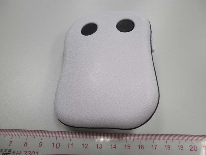
YCHIVACPRO
May 04, 2011iVAC pro Remote
Equipment Class
DSC - Part 15 Security/Remote Control Transmitter