YCMDZZBSADZ-ZB-S-A Zigbee Module
DIZIC Co., Ltd.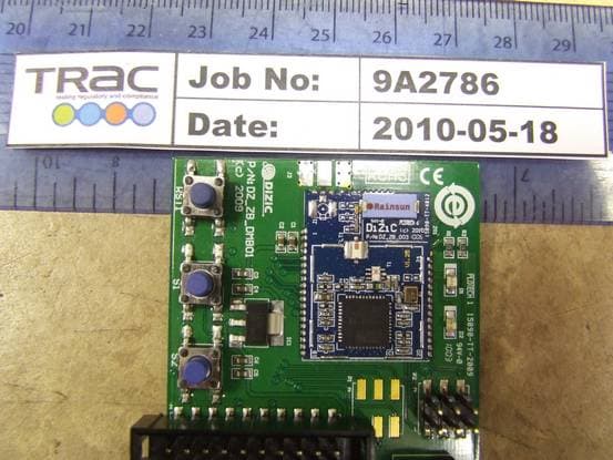
Click to zoom
Application Details
- Equipment Class
- DTS - Digital Transmission System
- Date of Grant
- Jul 28, 2010
- Application Purpose
- Original Equipment
- Date of Application
- Jul 28, 2010
- Equipment Note
- DZ-ZB-S-A Zigbee Module
- Frequency Range
- 2400.00000000 - 2483.50000000
- Company
- DIZIC Co., Ltd.
- Country
- Taiwan
Documents & Files
Document Text
Text extracted from the exhibit documents filed with the FCC. Open a document above to read the original.
Users Manual
802.15.4 Family of RF Modules High Performance and Long Range July 2010Doc ID: PB-ZB-MOD-003-20DSPage i DiZiC 802.15.4 DZ-ZB RF Modules Quickly add wireless capability with these high performance ZigBee compliant modules © 2010 DiZiC Co. Ltd. Subject to change without notice. The DiZiC DZ-ZB 802.15.4 Modules allow you to quickly add wireless networking capabilities to your products. These ZigBee-compliant modules are ready-to-use, simple to operate, and available in a wide range of configurations. They are ideal for industrial sensors, consumer remote controls, home appliances, and more. Features +STM32W108 ZigBee / IEEE 802.15.4 SoC • Complete System-on-Chip • 32-bit ARM® Cortex-M3 processor • 2.4 GHz IEEE 802.15.4 transceiver & lower MAC • Supports 16 channels • 128 kB flash, 8 kB SRAM memory • 128-bit AES encryption accelerator • Flexible ADC, SPI/UART/TWI serial communications, and general purpose timers • 24 highly configurable GPIO with Schmitt trigger inputs • Data rate up to 250 kbit/s +Low power consumption, advanced management: • RX Current (w/ CPU): 27 mA • TX Current (w/ CPU, +3 dBm TX): 31 mA • Low deep sleep current with retained RAM and GPIO: 400 nA/ 800 nA with/without sleep timer • Low-frequency internal RC oscillator for low-power sleep timing • High-frequency internal RC oscillator for fast (100 μsec) processor start-up from sleep +Innovative network and processor debug: • Serial Wire/JTAG interface • Standard ARM debug capabilities: Flash Patch & Breakpoint; Data Watch-point & Trace; Instrumenta- tion Trace Macrocell +Exceptional RF Performance • Normal mode Link Budget up to 102 dB; configurable up to107 dB • -99 dBm normal RX sensitivity; configurable to -100 dBm (1%PER, 20 byte packet) • +3 dB normal mode output power; configurable up to +7 dBm • Robust WiFi and Bluetooth coexistence +Application Flexibility: • Single voltage operation: 2.1 V to 3.6 V • Optional 32.768 kHz crystal for higher timer accuracy • Low external component count with single 24 MHz crystal • External power amplifier versions +Peripherals • 24 GPIOs, SPI, USART, and I2C • 12-bit ADC with up to 6 inputs • 2x 16-bit timers • DMA controller +Power Level Options: • standard power level (+7 dBm) • Or two RF Front End (PA and LNA, +20 dBm) ver- sions. +RF Output Options: • Chip antenna • U.FL connector • Single port 50 Ohm RF pad. +ZigBee Software Stack Options: • EmberZNet PRO ZigBee stack • RF4CE stack • Low level PHY / MAC stack. +EMI Options: • Standard version without shielding • Metal shielding protection Target Applications • Smart Energy • Building automation and control (HVAC) • Home automation and control • Security and monitoring • AMR/AMI • Logistic & Asset tracking • Medical • General ZigBee wireless sensor networking • Active RFID • Wireless hand-held terminals • Industry telemetry /automatic data collection • Temperature and humidity control systems • Traffic and control for street lamp Table of Contents DiZiC 802.15.4 DZ-ZB RF Modules July 2010Doc ID: PB-ZB-MOD-003-20DSPage ii © 2010 DiZiC Co. Ltd. Subject to change without notice. Table of Contents List of Tables ..................................................................................................................................................................... iii List of Figures ................................................................................................................................................................... iv 1. Product Approvals ........................................................................................................................................................ 1 1.1. FCC Approvals ....................................................................................................................................................... 1 1.2. IC (Industry Canada) Approvals ............................................................................................................................. 1 1.3. European Certification (ETSI) ................................................................................................................................ 1 2. Configurations .............................................................................................................................................................. 3 2.1. Power Level Options: Codes [S] [R] or [T] ............................................................................................................. 4 2.2. RF Output Options: Codes [A] [P] or [U] ................................................................................................................ 4 2.3. ZigBee Stack Options: Codes [F] [X] or [Z] ............................................................................................................ 4 2.4. EMI Protection Options: [M] or [S] .......................................................................................................................... 5 2.5. Configuration Options Matrix .................................................................................................................................. 5 3. Block Diagram ............................................................................................................................................................... 7 4. Absolute Maximum Ratings ......................................................................................................................................... 8 4.1. Voltage Characteristics .......................................................................................................................................... 8 4.2. Current Characteristics .......................................................................................................................................... 8 4.3. Thermal Characteristics .........................................................................................................................................…
Text truncated - open the document above for the full version.
Users Manual
RainSun Corporation http://www.rainsun.com 1of 9 Aug, 2006 Ver.1.1 AN0835 Multilayer Chip Antenna for 2.4GHz Wireless Communication RainSun Corporation http://www.rainsun.com 2of 9 Aug, 2006 Ver.1.1 AN0835 Multilayer Chip Antenna ◆Features yLight weight and low profile 8.0mm(L) ×3.5mm(W) ×1.0mm(H) yOmni-directional in azimuth yLead (Pb) Free ◆ Applications Applications y2.4GHz wireless communications y2.4GHz Modules yBluetooth System y802.11b/g Wireless LAN System Specifications 2.45 GHz 1 dBi -40 °C ~ +85 °C -40 °C ~ +85 °C 2.0 (max) 50 Ohm 3W (max) 180 MHz Omni-directional Linear Center frequency Peak gain Operation temperature Storage temperature VSWR Input Impedance Power handling Bandwidth Azimuth beamwidth Polarization RainSun Corporation http://www.rainsun.com 3of 9 Aug, 2006 Ver.1.1 Solder termination3 Feed point mark2 Feed termination1 Pin assignmentPin No Pin configuration 0.30 ±0.05E 1.00 ±0.20H 0.50 ±0.05D 1.50 ±0.02C 3.50 ±0.10B 8.00 ±0.10A Dimensions(mm)Symbol Dimensions 1 3 2 Top view PCB Foot Print 8.0I 1.9H 1.0G Dimensions(mm)Symbol RainSun Corporation http://www.rainsun.com 4of 9 Aug, 2006 Ver.1.1 Ground Plane Board thickness : 0.6mm Board material : FR4 Unit : mm 50 Ohm Transmission line SMA connector Top viewBottom view Recommended Test Board Pattern Testing Setup Measurement Testing Instrument: Anritsu 37369C VNA(Vector Network Analyzer) VNA calibrate with 1 path reflection only calibration sequence on test board feed point. The test board dimension and it’s layout is the same as Fig‐1. Fig-1 RainSun Corporation http://www.rainsun.com 5of 9 Aug, 2006 Ver.1.1 Return loss Typical Electrical Characteristics Smith Chart Marker data: 1 : f=2.556 GHz 2 : f=2.368 GHz 3 : f=2.451 GHz RainSun Corporation http://www.rainsun.com 6of 9 Aug, 2006 Ver.1.1 2.45 GHz H‐Plane 2.45 GHz E‐Plane Typical Radiation Patterns RainSun Corporation http://www.rainsun.com 7of 9 Aug, 2006 Ver.1.1 Typical Soldering Profile for Lead‐free Process Temperature ( °C ) Time (sec.) 340°C 300°C 150°C Peak temp 340°C Do not exceed 30 secs. 25 sec. 5 sec. Pre-heating Temperature ( °C ) Time (sec.) 260°C 230°C 180°C 10 sec, max Reflow Soldering 60 sec. 30 sec. Pre-heating RainSun Corporation http://www.rainsun.com 8of 9 Aug, 2006 Ver.1.1 Packing Blister Tape Specifications mm±0. 101.40K 0 mm±0.050.30T mm±0.108.20B 0 mm±0.103.70A 0 mm±0.102.00P 2 mm±0.108.00P mm±0.104.00P 0 mm +0.25 ‐0.00 1.50D 1 mm±0.101.50D mm±0.107.50F mm±0.101.75E mm±0.3016.00W UnitToleranceDimensionSymbol RainSun Corporation http://www.rainsun.com 9of 9 Aug, 2006 Ver.1.1 Reel Specifications 16.7±0.3 W (mm) 19.5±1.02.2±0.560±0.513±0.2178±1161,000 W 1 (mm) E (mm) B (mm) C (mm) A (mm) Tape Width (mm) Quantity Per Reel
Attestation Statements
© 2010 DiZiC Co. Ltd, 3F, N° 4-2 Jin Xi Street Taipei City 104, TAIWAN Web: www.dizic.com All Rights Reserved. All trademarks are property of their respective owners. Subject to change without notice. Letter of Agency 10 th June 2010 TRaC Global 100 Frobisher Business Park Leigh Sinton Road Malvern Worcestershire WR14 1BX UK To Whom It May Concern: We certify that we are not subject to denial of federal benefits, that includes FCC benefits, pursuant to Section 5301 of the Anti-Drug Abuse ACT of 1988, U.S.C. 862. Further, no party, as defined in 47 CFR 1.2002(b), to the application, is subject to denial of federal benefits, that includes FCC benefits. Thank you for your attention to this matter. Yours faithfully DiZiC Co., Ltd. Ling Jung CHEN Managing Director
Cover Letter(s)
Copyright 2010 © STMicroelectronics MMS GROUP MCD Division TRAC AUTHORISATION TO PASS INFORMATION TO DIZIC May 3 rd 2010 STMicroelectronics 109, Rue Celestin Coq 13106 ROUSSET To Whom It May Concern: Please be advised that the following, STMicroelectronics SAS authorizes TRaC to provide any information, document and measurements results needed to DiZiC Co., Ltd. in order to allow them to re- apply for the product certification. Thank you for your attention to this matter. Yours faithfully STMicroelectronics SAS Signature Francis Dell’ova
Cover Letter(s)
© 2010 DiZiC Co. Ltd, 3F, N° 4-2 Jin Xi Street Taipei City 104, TAIWAN Web: www.dizic.com All Rights Reserved. All trademarks are property of their respective owners. Subject to change without notice. REQUEST FOR CONFIDENTIALITY I N ACCORDANCE WITH FCC RULE 0.459 July 29 th 2010 TRaC Global 100 Frobisher Business Park Leigh Sinton Road Malvern Worcestershire WR14 1BX UK RE: Certification Application FCC ID: YCMDZZBSA To Whom It May Concern: Please be advised that the following information is to be held confidential on behalf of DiZiC Co., Ltd. . • Block diagram • Parts list • Schematics The application contains technical information which DiZiC Co., Ltd deems to be trade secrets and propriety. If made public, the information might be used to the disadvantage of the applicant in the market place. Thank you for your attention to this matter. Yours faithfully DiZiC Co., Ltd. Ling Jung CHEN Managing Director
RF Exposure Info
Appendix G:MPE Calculation OET Bulletin No. 65, Supplement C 01-01 47 CFR §§1.1307 and 2.1091 2.1091 Radio frequency radiation exposure evaluation: mobile devices. For purposes of these requirements mobile devices are defined by the FCC as transmitters designed to beused in other than fixed locations and to generally be used in such a way that a separation distance of at least 20 centimetersis normally maintained between radiating structures and the body of the user or nearby persons. These devices are normally evaluated for exposure potential with relation to the MPE limits. As the 20cm separation specified under FCC rules may not be achievable under normal operation of the EUT, an RF exposure calculation is needed to show the minimum distance required to be less than 1mW/cm 2 power density limit, as required under FCC rules. Prediction of MPE limit at a given distance Equation from page 18 of OET Bulletin 65, Edition 97-01 where: S = power density P = power input to the antenna G = power gain of the antenna in the direction of interest relative to an isotropic radiator R = distance to the centre of radiation of the antenna Sample No.S03 Maximum peak output power at the antenna terminal:5.49dBm Maximum peak output power at the antenna terminal:3.53997341mW Power density1.00000000mW/cm 2 Antenna gain (typical):1dBi Maximum antenna gain:1.258925412numeric Prediction frequency:2405MHz Result Prediction Frequency (MHz) Maximum allowable antenna gain: (dBi) Power density limit (S) (mW/cm 2 ) Distance (R) cm required to be less than 1mW/cm 2 240511.000000 0.59551824 4 arranged-re 4 2 S EIRP R R EIRP S
Test Report
Total number of pages : 117 TRaC Wireless Test Report:9A2786WUS1 Applicant:ST Microelectronics Apparatus:DZ-ZB-S-A Specification(s):CFR47 Part 15C :2008 15.247 FCCID: YCPDZSTM32WA Purpose of Test: Certification Authorised by: : Radio Product Manager Issue Date:19 th March 2010 Authorised Copy Number: PDF Radio Test Report: 9A2786WUS1 2 Contents Section 1:Introduction3 1.1General3 1.2Tests Requested By4 1.3Manufacturer4 1.4Apparatus Assessed5 1.5Test Result Summary6 1.6Notes Relating To The Assessment7 1.7Deviations from Test Standards7 Section 2:Measurement Uncertainty8 2.1Application of Measurement Uncertainty8 2.2Measurement Uncertainty Values9 Section 3:Modifications10 3.1Modifications Performed During Assessment10 Appendix A:Formal Emission Test Results11 A16 dB Bandwidth12 A2Transmitter Peak Output Power13 A3Transmitter Power Spectral Density14 A4RF Antenna Conducted Spurious Emissions15 A5Transmit Radiated Electric Field Emissions 15.209 and within the Restricted Bands of 15.20519 A6Power Line Conducted Emissions24 A7Antenna Gain27 A8Unintentional Radiated Electric Field Emissions - 15.10928 Appendix B:Supporting Graphical Data30 Appendix C:Additional Test and Sample Details88 Appendix D:Additional Information94 Appendix E:Calculation of the duty cycle correction factor103 Appendix F:Photographs and Figures108 Appendix G:MPE Calculation116 Radio Test Report: 9A2786WUS1 3 Section 1:Introduction 1.1General This report contains an assessment of an apparatus against ElectromagneticCompatibility Standards based upon tests carried out on samples submitted to the Laboratory. Test performed at:TRaC Telecoms & Radio[ X ] Unit E South Orbital Trading Park Hedon Road Hull, HU9 1NJ. United Kingdom. Telephone:+44 (0) 1482 801801 Fax:+44 (0) 1482 801806 TRaC Telecoms & Radio[ ] Moss View Nipe Lane Up Holland West Lancashire, WN8 9PY United Kingdom Telephone:+44 (0) 1695 556666 Fax:+44 (0) 1695 577077 Email:[email protected] Web site:http://www.tracglobal.com Tests performed by:M. E. Leach Report author:M. E. Leach This report must not be reproduced except in full without prior written permission from TRaC Telecoms & Radio. Radio Test Report: 9A2786WUS1 4 1.2Tests Requested By This testing in this report was requested by : STMicroelectronics 190 Avenue Célestin Coq 13106 Rousset Cedex France 1.3Manufacturer DIZIC Co. Ltd 3F, No 4-2 in Xi Street Zhong Shan District 104 Taipei Taiwan Radio Test Report: 9A2786WUS1 5 1.4Apparatus Assessed The followingapparatus was assessed between: 12/04/10 to 22/04/10 DZ-ZB-S-A The aboveapparatus was a.2.4GHz ZigBee radiotransceiver. Radio Test Report: 9A2786WUS1 6 1.5Test Result Summary Full details of testresults are contained within Appendix A. The following table summarises the results of the assessment. The statements relating to compliance with the standards below apply ONLY as qualified in the notes and deviations stated in sections 1.6 to 1.7 of this test report. Full details of test results are contained within Appendix A. The following table summarises the results of the assessment. Test TypeRegulation Measurement standard Result Radiated spurious emissions (Restricted bands) Title 47 of the CFR: Part 15 Subpart C; 15.247 ANSI C63.10Pass Conducted spurious emissions (Non-restricted bands) Title 47 of the CFR: Part 15 Subpart C; 15.247 ANSI C63.10Pass AC Power conducted emissions Title 47 of the CFR: Part 15 Subpart C; 15.207 ANSI C63.10Pass Occupied Bandwidth Title 47 of the CFR : Part 15 Subpart C; 15.247(a)(2) ANSI C63.10Pass Conducted Carrier Power Title 47 of the CFR : Part 15 Subpart C; 15.247(b) ANSI C63.10Pass Power Spectral Density Title 47 of the CFR : Part 15 Subpart C; 15.247(d) ANSI C63.10Pass Unintentional Radiated Spurious Emissions Title 47 of the CFR: Part 15 Subpart C; 15.109 ANSI C63.10Pass Digital Modulation Title 47 of the CFR: Part 15 Subpart C; 15.403 -Pass RF Safety Title 47 of the CFR : Part 15 Subpart C; 15.247(b)(5) -Pass Radio Test Report: 9A2786WUS1 7 1.6Notes Relating To The Assessment With regard to this assessment, the following points should be noted: The results contained in this report relate only to the items tested and were obtained in the period between the date of initial receipt of samples and the date of issue of the report. The apparatus was set up and exercised using the configurations, modes of operation and arrangements defined in this report only. Particular operating modes, apparatus monitoring methods and performance criteria required by the standards tested to have been performed except where identified in Section 1.7 of this test report (Deviations from Test Standards). For emissions testing, throughout this test report, “Pass” indicates that the results for the sample as tested were below the specified limit (refer also to Section 2, Measurement Uncertainty). Where relevant, the apparatus was only assessed using the monitoring methods and susceptibility criteria defined in this report. All testing with the exception of testing at the Open Area Test Site was performed under the following environmental conditions: Temperature: 17 to 23 C Humidity : 45 to 75 % Barometric Pressure: 86 to 106 kPa All dates used in this report are in the format dd/mm/yy. This assessment has been performed in accordance with the requirements of ISO/IEC 17025. 1.7Deviations from Test Standards There were no deviations from the standards tested to. Radio Test Report: 9A2786WUS1 8 Section 2:Measurement Uncertainty 2.1Application of MeasurementUncertainty The following table contains the measurement uncertainties for measurements The following procedure is used when determining the result of a measurement : (i)If specification limits are not exceeded by the measured result, extended by the positive component of the expanded uncertainty interval at a confidence level of 95%, then a pass result is recorded. (ii)Where a specification limit is exceeded by the result even when the result is decreased by the negative component of the ex…
Text truncated - open the document above for the full version.
Contact Information
Applicant
Daniel Joseph MASTIO(General Manager)
Test Firm
Element Materials Technology Warwick LtdMax Leach
Technical Specifications
| # | Rule Parts | Frequency Range | Power Output | Tolerance |
|---|---|---|---|---|
| 1 | 15C | 2.40 GHz - 2.48 GHz | 3.54 mW | 40.0000000000 ppm |
Other Applications from DIZIC Co., Ltd.
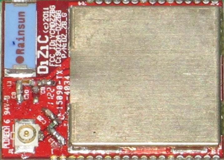
YCMDZZBG
Dec 25, 20122.4GHz RF Modular
Equipment Class
DTS - Digital Transmission System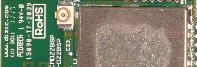
YCMDZZBSP
Dec 25, 20122.4GHz RF Modular
Equipment Class
DTS - Digital Transmission System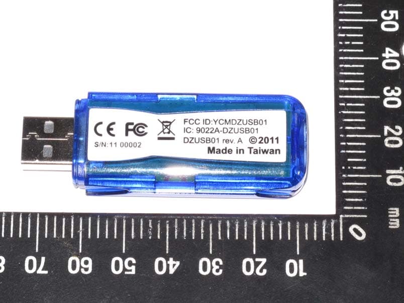
YCMDZUSB01
Dec 22, 2011Contactless card reader
Equipment Class
DTS - Digital Transmission System