YDM-CA1505GPS enabled cycling computer
Bryton Incorporation
Click to zoom
Application Details
- Equipment Class
- DTS - Digital Transmission System
- Date of Grant
- Aug 17, 2015
- Application Purpose
- Original Equipment
- Date of Application
- Aug 16, 2015
- Equipment Note
- GPS enabled cycling computer
- Frequency Range
- 2402.00000000 - 2480.00000000
- Company
- Bryton Incorporation
- Country
- Taiwan
Documents & Files
Document Text
Text extracted from the exhibit documents filed with the FCC. Open a document above to read the original.
Users Manual
Settings23 Language Language English Deutsch Français 1. In the Settings menu, press to select General > System > Language and press . 2. Press / to select the desired setting and press 3. Press to exit this menu. View GPS Status You can view the GPS signal information that your device is currently receiving. 1. In the Settings menu, press to select General > GPS and press . 2. To set the signal search mode, press 3. Press / to select the desired setting and press • this to save power when GPS signal is not available, or when GPS information is not required (such as indoor use). Full Power: maximum position and • speed accuracy, consumes more power. PowerSaving: Achieves longer battery • life when used in good GPS signal condition, but less accurate. GPS PowerSave Full Power Off ENGLISH Settings24 View Software Version You can view your device current software version. 1. In the Settings menu, press to select General > About. 2. Press to confirm. The current software version is displayed on the screen. 3. Press to exit this menu. Appendix 25 Appendix Specifications Rider 310 ItemDescription Display 1.8" FSTN positive transflective dot-matrix LCD Physical Size45.1 x 71.9 x 17.3 mm Weight54g Operating Temperatur e -10°C ~ 50°C Battery Charging Temperature 0°C ~ 40°C BatteryLi polymer rechargeable battery Battery Life 20 hours with open sky GPS Integrated high-sensitivity GPS receiver with embedded an tenna RF Transceiver 2.4GMHz receiver with embedded antenna to support ANT+ heart rate, speed sensor, cadence sensor Water ResistantIPX7 waterproof rating Cadence Sensor ItemDescription Physical size33.9 x 13.5 x 39 mm Weight14 g Water ResistanceIPX7 Transmission range5 m Battery life1 hour per day for 16 months Operating temperature-10 o C ~ 60 o C Radio frequency/protocol 2.4GHz / Dynastream ANT+ Sport wireless communications protocol Accuracy may be degraded by poor sensor contact, electrical interference, and receiver distance from the transmitter. BLE Smart Bluetooth smart wireless technology with embedded antenna ENGLISH Appendix26 Heart Rate Monitor ItemDescription Physical size67~100 x 26 x 15 mm Weight14 g (sensor) / 35g (strap) Water Resistance20 m Transmission range5 m Battery life1 hour per day for 24 months Operating temperature5 o C ~ 40 o C Radio frequency/protocol 2.4GHz / Dynastream ANT+ Sport wireless communications protocol Accuracy may be degraded by poor sensor contact, electrical interference, and receiver distance from the transmitter. Battery Information Heart Rate Monitor and Cadence Sensor Battery The heart rate monitor/cadence sensor contains a user-replaceable CR2032 battery. To replace the battery: 1. Locate the circular battery cover on the back of the heart rate monitor/cadence sensor. 2. Use a coin to twist the cover counter-clockwise so the arrow on the cover points to OPEN. 3. Remove the cover and battery. Wait for 30 seconds. 4. Insert the new battery, with the positive connector first into the battery chamber. 5. Use a coin to twist the cover clockwise so the arrow on the cover points to CLOSE. A B NOTE: When installing a new battery, if the battery is not placed with the positive connector • first, the positive connector will easily deform and malfunction. Be careful not to damage or lose the O-ring gasket on the cover.• Contact your local waste disposal department to properly dispose of used batteries.• A C L O S E O P E N B 3 12 12 4 Appendix27 In stall Rider 310 Mount Rider 310 to the Bike Install the Speed/Cadence/Dual Sensor (Optional) CADENCESPEED SPEED S P E E D 3 mm SPEED SP EED SPEED SPEED Speed Turn Off Status: active ID XXXXXXXXX Rescan SPEED Speed Turn Off Status: active ID XXXXXXXXX Rescan Cadence Turn Off Status: active ID XXXXXXXXX Rescan 1234 5a6a7a8a 5b6b7b8b Cadence Turn Off Status: active ID XXXXXXXXX Rescan 3 mm CADENCE 6c7c8c5c 3 mm Speed/CAD Turn Off Status: active ID XXXXXXXXX Rescan Speed/CAD Turn Off Status: active ID XXXXXXXXX Rescan ENGLISH Appendix28 Appendix 29 NOTE: To ensur• e optimum performance, do the following: - Align both sensor and magnet as shown in the illustration (5a / 5b). Pay attention on the alignment points. - Ensure the distance between the sensor and the magnet is within 3 mm. Ensure that both Speed sensor and Speed magnet are installed and aligned horizontally, • not vertically. On the initial usage, press the front button to activate the sensor and start pedaling. • When the sensor detects the magnet, the LED blinks once to indicate the alignment is correct (the LED blinks only for the first ten passes after pressing the button). Install Heart Rate Belt (Optional) Electrodes Strap C L O S E O P E N C L O S E O P E N C L O S E O P E N 1234 56 C L O S E O P E N NOTE: In cold weather, wear appropriate clothing to keep the heart rate belt warm.• The belt should be worn directly on your body.• Adjust the sensor position to the middle part of the body (wear it slightly below the • chest). The Bryton logo shown on the sensor should be facing upward. Tighten the elastic belt firmly so that it will not turn loose during the exercise. If the sensor cannot be detected or the reading is abnormal, please warm up for about 5 • minutes. If the heart rate belt is not used for a period of time, remove the sensor from the heart • rate belt. ENGLISH Appendix30 Wheel Size and Circumference The wheel size is marked on both sides of the tires. Wheel SizeL (mm) 24 x 1.751890 24 x 2.001925 24 x 2.1251965 26 x 7/81920 26 x 1(59)1913 26 x 1(65)1952 26 x 1.251953 26 x 1-1/81970 26 x 1-3/82068 26 x 1-1/22100 26 x 1.402005 26 x 1.502010 26 x 1.752023 26 x 1.952050 26 x 2.002055 700 x19C2080 700 x 20C2086 700 x 23C2096 700 x 25C2105 700 x 28C2136 700 x 30C2170 700 x 32C2155 700C Tubular2130 700 x 35C2168 700 x 38C2180 700 x 40C2200 Wheel SizeL (mm) 12 x 1.75935 14 x 1.51020 14 x 1.751055 16 x 1.51185 16 x 1.751195 18 x 1.51340 18 x 1.751350 20 x 1.751515 20 x 1-3/81615 22 x 1-3/81770 22 x 1-1/21785 24 x 11753 24 x 3/4 Tubular1785 24 x 1-…
Text truncated - open the document above for the full version.
Users Manual
ENGLISH Getting Started5 Accessories The Rider 320 comes with the following accessories: USB cable • Bike mount• Optional items: Heart rate belt• Speed sensor • Cadence sensor• Speed/Cadence Dual sensor• Status Icons IconDescriptionIconDescription Bike Type Heart Rate Sensor Active 1 Bike 1Cadence Sensor Active 2 Bike 2Speed Sensor Active GPS Signal Status Dual Sensor Active No signal (not fixedNotification Weak signalLog Record in Progress Strong signalRecording is paused Power Status Bluetooth function is enabled Full battery / Half battery Low battery NOTE: Only the active icons are displayed on the screen. • Out-front Bike Mount /- - - reset Getting Started6 Step 1: Charge your Rider 320 Connect Rider 320 to a PC to charge the battery for at least 4 hours. Unplug the device when it is fully charged. Step 2: Turn On Rider 320 Press and hold to turn on the device. Step 3: Initial Setup When turning Rider 32 instructions to complete setup. 1. Select the display language. 2. Read and accept the Safety Agreement. ENGLISH Getting Started7 Step 4: Acquire Satellite Signals Once the Rider 320 is turned on, it will automatically search for satellite signals. It may take 30 to 60 seconds to acquire signals. Please make sure you acquire the satellite signal for the The GPS signal icon ( / • icon appears on the screen. • TunnelsInside rooms, building, or underground Under water High-voltage wires or television towers Construction sites and heavy Step 5: Ride Your Bike with Rider 320 Free ride:• In meter view, measurement starts and stops automatically in sync with the movement of the bicycle. Start an exercise and record your data:• In meter view, press to start recording, press to pause, press again to stop. Start a training:• Select Train from the menu list. Training can be based on time, distance, calories burn, or the saved workouts. Reset Rider 320 To reset the Rider 320, long press all three keys (//) at the same time. Getting Started 8 Share Your Records Download Bryton Update Tool Share Your Records Download Bryton Update Tool Training9 Train & Test Bicycling is one of the best types of exercise for your body. It helps you to burn your calories, 320 Training feature, you can set simple workouts and use the Rider 320 to track your training or workout progress. 1. In the main screen, press to select Train&Test. 2. Press to enter the Training menu. 08:08 09/09 Cycling Train & Test View History Settings To Plan You can set simple workouts by entering your time or distance goals. The Rider 32 Simple 1. To set a simple workout, select To Plan > Simple > Warm Up, Work , Cooldown. 2. Press / to set your time and press 3. Choose Save and enter the workout name using the on-screen keyboard. 4. Go for a ride. Go to Train & Test > My Workouts > View and choose the save workout. Press to start training and record log. 6’ 0” 159 ~ 171 10’ 94 ~ 111 10’ 94 ~ 111 Work Warm Up Cooldwn Simple ENGLISH Training 10 Using the On-screen Keyboard Name Save 001END Name Save 001A 1. Press / to select the input character. Select • DEL to erase the data. 2. Press s / to select END and press NOTE: name according to the current date and time. My Workout With My Workout feature, you can start your workout using the training plan that you have saved in To Plan menu. 1. In the Training menu, press to select My Workout and press . 2. Press to select View and press to enter its submenu. Press • to select your desired training plan and press Go for a ride.• Press to start training and record log. 3. To choose which workouts to delete, select Delete. 4. To delete all workouts to delete, select Delete All. View Delete Delete All My Workout Training11 NOTE: If the selected workout includes several interval settings, a workout details appear on the screen. Select Start and press to proceed with the workout. Stop Training You can stop the current training after you have reached your goal or when you decide to end the current training. / 1 1 / 1 1 r p m 1. Press to pause the recording and press again to stop the recording. 2. A “Do you want to stop?” message appears on the screen. To stop the current training, press / to select Yes and press View Exercise/Training Record Use View History to view or delete your exercise/training history. To view your history: 1. In the main screen, press to select View History > View and press. 2. Press to select View and press to 3. Press to select a training history from the list and press to view your history. NOTE: You can also upload your history to brytonsport.com to keep track of all your ride data. Summary View Delete All Delete History Do you want to stop? Yes ENGLISH Training 12 To delete your history: 1. In the main screen, press to select View History > View and press . 2. Press to select Delete and press to enter the history list. 3. Press to select a training history from the list and press to delete the selected history. 4. A “Do you want to delete?” message appears on the screen. To delete the data, press / to select Yes and press Delete Do you want to delete? Yes History Flow 09/1921:44 00:03:08trip 3.69km 39kcal 04laps 1/20 More 00:02:25ride AVGMAX 75.6kmh 39bpm 19rpm 75.6 39 19 Lap 0100:49 0.25km 81.4kmh 13kcal 0bpm 0rpm trip = Trip Time The arrow appears only when there is lap in this record. Record#/Total records The arrow appears only when there are more than 1 lap. Settings13 Settings With the Settings feature, you can customize exercises settings, altitude, general settings, sensor settings, bike and user pr Exercises Altitude General Sensors Settings 1. In the main screen, press to select Settings. 2. Press to enter the Settings menu. Smart Lap With Smart e. Lap by Location By Location Use current location as lap location? Yes 1. In the Settings menu, press to select Exercises> Smart Lap and press . 2. Press to enter the editing menu. 3. A “Use current location as lap location?” message appears on the screen. To save the data, press to select Yes and press 4. Press to exit…
Text truncated - open the document above for the full version.
Users Manual
CADENCESPEED SPEED SPEE D 3 mm SPEED SPEED SPEED SPEED Speed Turn Off Status: active ID XXXXXXXXX Rescan SPEED Speed Turn Off Status: active ID XXXXXXXXX Rescan Cadence Turn Off Status: active ID XXXXXXXXX Rescan 1234 5a6a7a8a 5b6b7b8b Cadence Turn Off Status: active ID XXXXXXXXX Rescan 3 mm CADENCE Speed/CAD Turn Off Status: active ID XXXXXXXXX Rescan 5c6c7c8c Speed/CAD Turn Off Status: active ID XXXXXXXXX Rescan 3 mm ENGLISH Appendix28 Install the Speed/Cadence/Dual Sensor (Optional) Appendix 29 NOTE: To ensur• e optimum performance, do the following: - Align both sensor and magnet as shown in the illustration (5a / 5b). Pay attention on the alignment points. - Ensure the distance between the sensor and the magnet is within 3 mm. Ensure that both Speed sensor and Speed magnet are installed and aligned horizontally, • not vertically. On the initial usage, press the front button to activate the sensor and start pedaling. • When the sensor detects the magnet, the LED blinks once to indicate the alignment is correct (the LED blinks only for the first ten passes after pressing the button). Install Heart Rate Belt (Optional) Electrodes Strap C L O S E O P E N C L O S E O P E N C L O S E O P E N 1234 56 C L O S E O P E N NOTE: In cold weather, wear appropriate clothing to keep the heart rate belt warm.• The belt should be worn directly on your body.• Adjust the sensor position to the middle part of the body (wear it slightly below the • chest). The Bryton logo shown on the sensor should be facing upward. Tighten the elastic belt firmly so that it will not turn loose during the exercise. If the sensor cannot be detected or the reading is abnormal, please warm up for about 5 • minutes. If the heart rate belt is not used for a period of time, remove the sensor from the heart • rate belt. ENGLISH Appendix30 Wheel Size and Circumference The wheel size is marked on both sides of the tires. Wheel SizeL (mm) 24 x 1.751890 24 x 2.001925 24 x 2.1251965 26 x 7/81920 26 x 1(59)1913 26 x 1(65)1952 26 x 1.251953 26 x 1-1/81970 26 x 1-3/82068 26 x 1-1/22100 26 x 1.402005 26 x 1.502010 26 x 1.752023 26 x 1.952050 26 x 2.002055 700 x19C2080 700 x 20C2086 700 x 23C2096 700 x 25C2105 700 x 28C2136 700 x 30C2170 700 x 32C2155 700C Tubular2130 700 x 35C2168 700 x 38C2180 700 x 40C2200 Wheel SizeL (mm) 12 x 1.75935 14 x 1.51020 14 x 1.751055 16 x 1.51185 16 x 1.751195 18 x 1.51340 18 x 1.751350 20 x 1.751515 20 x 1-3/81615 22 x 1-3/81770 22 x 1-1/21785 24 x 11753 24 x 3/4 Tubular1785 24 x 1-1/81795 24 x 1-1/41905 26 x 2.102068 26 x 2.1252070 26 x 2.352083 26 x 3.002170 27 x 12145 27 x 1-1/82155 27 x 1-1/42161 27 x 1-3/82169 650 x 35A2090 650 x 38A2125 650 x 38B2105 700 x 18C2070 Appendix 31 Basic Care For Your Rider 320 Taking good care of your device will reduce the risk of damage to your device. Do not drop your device or subject it to severe shock.• Do not expose your device to extreme temperatures and excessive moisture.• The screen surface can easily be scratched. Use the non-adhesive generic screen • protectors to help protect the screen from minor scratches. Use diluted neutral detergent on a soft cloth to clean your device.• Do not attempt to disassemble, repair, or make any modifications to your device. Any • attempt to do so will make the warranty invalid. NOTE: Improper battery replacement may cause an explosion. When replacing a new battery, use only the original battery or a similar type of battery specified by the manufacturer. Disposal of the used batteries must be carried out in accordance to the regulations of your local authority. For better environmental protection, waste batteries should be collected separately for recycling or special disposal. Screen Terminologies Screen DisplayTerminology LapAvSpdlap average speed LapMaSpdlap maximum speed L'stLpAvSplast lap average speed LapDistlap distance L'stLpDistlast lap distance L'stLapTlast lap time LapAvHRlap average heart rate LapMaHRlap maximum heart rate L'LpAvHRlast lap average heart rate L'A'MHR%lap average MHR percentage L'A'LTHR%lap average LTHR percentage Str'dRatestride rate AvStr'dRtaverage stride rate MaStr'dRtmaximum stride rate LpAvSt'dRlap average stride rate LpStr'dAvLlap stride average length LLpSt'dAvLlast lap stride average length AvSt'dl'gthaverage stride length AvgPaceaverage pace MaxPacemaximum pace L'st1kmPlast 1km/mile pace LapAvPlap average pace L'stLpAvPlast lap average pace LapMaPlap maximum pace LAvCADlap average cadence ODOodometer T to DestTime to Destination D to DestDistance to Destination Alt. GainAltitude Gain Alt. LossAltitude Loss Appendix 32 Screen DisplayTerminology Sunrisesunrise time Sunsetsunset time Avg Speedaverage speed Max Speedmaximum speed HRheart rate Avg HRaverage heart rate Max HRmaximum heart rate MHR Zonemaximum heart rate zone Avg CADaverage cadence Max CADmaximum cadence LLAvCADlast lap average cadence 3s Power3 seconds average power 30s Power30 seconds average power LLapMaxPW LapMaxPWlap maximum power last lap maximum power Avg Poweraverage power LapAvgPWlap average power LLapAvgPWlast lap average power MAP ZoneMaximum Aerobic Power Zone MAP% Maximum Aerobic Power Percentage FTP ZoneFunctional Threshold Power FTP%Functional Threshold Power Percentage PS L-R Left and Right Pedal Smoothness TE-LR Left and Right Torque E ectiveness PB L-R Left and Right Power Balance Avg PS-LR Average Left and Right Pedal Smoothness Avg TE-LR Average Left and Right Torque E ectiveness Avg PB L-R Average Left and Right Power Balance Max PS-LR Max TE-LR Max PB-LR Maximum Left and Right Pedal Smoothness Maximum Left and Right Torgue E ectiveness Maximum Left and Right Power Balance Federal Communication Commission Interference Statement This equipment has been tested and found to comply with the limits for a Class B digital device, pursuant to Part 15 of the FCC Rules. These limits are designed to provide reasonable protection against harmful interference in a residential installation. This equipment generates, uses an…
Text truncated - open the document above for the full version.
External Photos
Registration number: W6M21507-15109-FCC FCC ID: YDM-CA1505 Worldwide Testing Services(Taiwan) Co., Ltd. Appendix page 2 of 21 External Photos Registration number: W6M21507-15109-FCC FCC ID: YDM-CA1505 Worldwide Testing Services(Taiwan) Co., Ltd. Appendix page 3 of 21 Registration number: W6M21507-15109-FCC FCC ID: YDM-CA1505 Worldwide Testing Services(Taiwan) Co., Ltd. Appendix page 4 of 21 Registration number: W6M21507-15109-FCC FCC ID: YDM-CA1505 Worldwide Testing Services(Taiwan) Co., Ltd. Appendix page 5 of 21 Registration number: W6M21507-15109-FCC FCC ID: YDM-CA1505 Worldwide Testing Services(Taiwan) Co., Ltd. Appendix page 6 of 21 Registration number: W6M21507-15109-FCC FCC ID: YDM-CA1505 Worldwide Testing Services(Taiwan) Co., Ltd. Appendix page 7 of 21 Registration number: W6M21507-15109-FCC FCC ID: YDM-CA1505 Worldwide Testing Services(Taiwan) Co., Ltd. Appendix page 8 of 21 Registration number: W6M21507-15109-FCC FCC ID: YDM-CA1505 Worldwide Testing Services(Taiwan) Co., Ltd. Appendix page 9 of 21
ID Label/Location Info
310 FCC ID: YDM-CA1505 CCAJ15LP3430T7 IC :8957A-CA1505 CM IIT ID:XXXXXXXXXX KCC ID: MSIP-CMM-BYN-CA1505
Internal Photos
Registration number: W6M21507-15109-FCC FCC ID: YDM-CA1505 Worldwide Testing Services(Taiwan) Co., Ltd. Appendix page 10 of 21 Internal Photos Registration number: W6M21507-15109-FCC FCC ID: YDM-CA1505 Worldwide Testing Services(Taiwan) Co., Ltd. Appendix page 11 of 21 Registration number: W6M21507-15109-FCC FCC ID: YDM-CA1505 Worldwide Testing Services(Taiwan) Co., Ltd. Appendix page 12 of 21 Registration number: W6M21507-15109-FCC FCC ID: YDM-CA1505 Worldwide Testing Services(Taiwan) Co., Ltd. Appendix page 13 of 21 Registration number: W6M21507-15109-FCC FCC ID: YDM-CA1505 Worldwide Testing Services(Taiwan) Co., Ltd. Appendix page 14 of 21 Registration number: W6M21507-15109-FCC FCC ID: YDM-CA1505 Worldwide Testing Services(Taiwan) Co., Ltd. Appendix page 15 of 21 Registration number: W6M21507-15109-FCC FCC ID: YDM-CA1505 Worldwide Testing Services(Taiwan) Co., Ltd. Appendix page 16 of 21
RF Exposure Info
Registration number: W6M21507-15109-C-1 FCC ID: YDM-CA1505 Worldwide Testing Services(Taiwan) Co., Ltd. Page 15 of 30 3.2 RF Exposure Compliance Requirements FCC Rule: 15.247(b)(3) Test exclusion = max. conducted output power + adjusted for tune-up tolerance Test exclusion = -1.85 dBm + 0 dB (Claimed by the applicant) = -1.85 dBm RESULT: Test standard : FCC KDB Publication 447498 D01 General RF Exposure Guidance v05r02 According to 447498 D01 General RF Exposure Guidance v05r02: SAR evaluation, by measurement or numerical simulation, is not required when the corresponding SAR Exclusion Threshold condition, listed below, is satisfied. The enclosure of the device provides ≥ 0.5 cm separation from the antenna elements to significant metal parts of the enclosure to minimize potential perturbations. Frequency Band:2400-2483.5 MHz Maximum Power fed to Antenna: 0.6531 mW Separation distances: Radiator to user: > 5 mm Distance prescribed in user manual: > 5 mm MHz 5 10 15 20 25 mm 2450 10 19 29 38 48 SAR Test Exclusion Threshold (mW) MHz 30 35 40 45 50 mm 2450 57 67 77 86 96 SAR Test Exclusion Threshold (mW) MHz 50 60 70 80 90 100 110120130140150160170 180 190 mm 2450 96 196 296 396496 596 696796896996109611961296 1396 1496 mW
Test Report
of Applicant: Bryton Inc. Address: 3F-1., No.79-1, Zhouzi St., Neihu Dist., Taipei City 114, Taiwan Tested and Prepared by Worldwide Testing Services (Taiwan) Co., Ltd. FCC Registration No.: 930600 Industry Canada filed test laboratory Reg. No. IC 5679A-1, IC 5107A-1 A2LA Accredited No.: 2732.01 Report No.: W6M21507-15109-C-1 6F, NO. 58, LANE 188, RUEY-KUANG RD., NEIHU TAIPEI 114, TAIWAN, R.O.C. TEL: 886-2-66068877 FAX: 886-2-66068879 E-mail: [email protected] FCC PART 15 SUBPART C TEST REPORT for GPS enabled cycling computer Model No.: Rider 310 FCC ID: YDM-CA1505 Registration num ber: W6M21507-15109-C-1 FCC ID: YDM-CA1505 Worldwide Testing Services(Taiwan) Co., Ltd. Page 1 of 30 TABLE OF CONTENTS 1 GENERAL INFORMATION.........................................................................................................................................2 1.1 NOTES......................................................................................................................................................................2 1.2 TESTING LABORATORY.............................................................................................................................................3 1.2.1 Location ..............................................................................................................................................................3 1.2.2 Details of accreditation status ............................................................................................................................3 1.3 DETAILS OF APPROVAL HOLDER...............................................................................................................................3 1.4 APPLICATION DETAILS..............................................................................................................................................4 1.5 GENERAL INFORMATION OF TEST ITEM.....................................................................................................................4 1.6 TEST STANDARDS.....................................................................................................................................................5 2 TECHNICAL TEST........................................................................................................................................................6 2.1 SUMMARY OF TEST RESULTS.....................................................................................................................................6 2.2 TEST ENVIRONMENT.................................................................................................................................................6 2.3 TEST EQUIPMENT LIST..............................................................................................................................................7 2.4 GENERAL TEST PROCEDURE.....................................................................................................................................9 3 TEST RESULTS (ENCLOSURE) ...............................................................................................................................11 3.1 PEAK OUTPUT POWER (TRANSMITTER)...................................................................................................................12 3.2 RF EXPOSURE COMPLIANCE REQUIREMENTS ........................................................................................................15 3.3 TRANSMITTER RADIATED EMISSIONS IN RESTRICTED BANDS................................................................................16 3.4 SPURIOUS EMISSIONS (TX)......................................................................................................................................17 3.5 RADIATED EMISSION ON THE BAND EDGE...............................................................................................................19 3.6 MINIMUM 6 DB BANDWIDTH..................................................................................................................................21 3.7 PEAK POWER SPECTRAL DENSITY..........................................................................................................................24 3.8RADIATED EMISSION FROM DIGITAL PART.............................................................................................................27 3.9 POWER LINE CONDUCTED EMISSION......................................................................................................................28 APPENDIX.............................................................................................................32 Registration number: W6M21507-15109-C-1 FCC ID: YDM-CA1505 Worldwide Testing Services(Taiwan) Co., Ltd. Page 2 of 30 1 General Information 1.1 Notes The purpose of conformity testing is to increase the probability of adherence to the essential requirements or conformity specifications, as appropriate. The complexity of the technical specifications, however, means that full and thorough testing is impractical for both technical and economic reasons. Furthermore, there is no guarantee that a test sample which has passed all the relevant tests conforms to a specification. Neither is there any guarantee that such a test sample will interwork with other genuinely open systems. The existence of the tests nevertheless provides the confidence that the test sample possesses the qualities as maintained and that is performance generally conforms to representative cases of communications equipment. The test results of this test report relate exclusively to the item tested as specified in 1.5. The test report may only be reproduced or published in full. Reproduction or publication of extracts from the report requires the prior written approval of the Worldwide Testing Services(Taiwan) Co., Ltd. Tester: July 24, 2015 Spencer Yang Date WTS-Lab. Name Signature Technical responsibility for area of testing: July 24, 2015 Ke…
Text truncated - open the document above for the full version.
Test Setup Photos
Registration number: W6M21507-15109-FCC FCC ID: YDM-CA1505 Worldwide Testing Services(Taiwan) Co., Ltd. Appendix page 17 of 21 Set Up Photo of Radiated Emission Battery Below 1GHz Registration number: W6M21507-15109-FCC FCC ID: YDM-CA1505 Worldwide Testing Services(Taiwan) Co., Ltd. Appendix page 18 of 21 Above 1GHz Registration number: W6M21507-15109-FCC FCC ID: YDM-CA1505 Worldwide Testing Services(Taiwan) Co., Ltd. Appendix page 19 of 21 Charge Below 1GHz Registration number: W6M21507-15109-FCC FCC ID: YDM-CA1505 Worldwide Testing Services(Taiwan) Co., Ltd. Appendix page 20 of 21 Above 1GHz Registration number: W6M21507-15109-FCC FCC ID: YDM-CA1505 Worldwide Testing Services(Taiwan) Co., Ltd. Appendix page 21 of 21 Set Up Photo of Conducted Emission
Contact Information
Applicant
Vic Chen(Director)
Technical Contact
Worldwide Testing Services (Taiwan) Co., Ltd.Danny Sung
[email protected]886-2-6606-8877
6F., No.58, Lane 188, Ruey Kuang Rd., · Taiwan
Non-Technical Contact
Worldwide Testing Services (Taiwan) Co., Ltd.Lynn Kao
[email protected]886-2-6606-8877
Test Firm
Worldwide Testing Services (Taiwan) Co., Ltd.Rex Kao
Technical Specifications
| # | Rule Parts | Frequency Range | Power Output |
|---|---|---|---|
| 1 | 15C | 2.40 GHz - 2.48 GHz | 700.00 µW |
Other Applications from Bryton Incorporation

YDM-DE2505
Dec 29, 2025Bryton Smart Heart rate sensor
Equipment Class
DTS - Digital Transmission System
YDM-CA2203
Mar 28, 2023GPS enabled cycling computer
Equipment Class
DTS - Digital Transmission System
YDM-CA1902
May 21, 2020GPS enabled cycling computer
Equipment Class
DTS - Digital Transmission System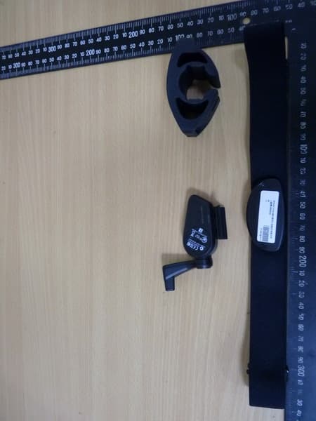
YDM-BA1404
Jul 27, 2014GPS Sports Watch
Equipment Class
DTS - Digital Transmission System
YDM-RIDER30
Oct 26, 2010GPS enabled cycling computer
Equipment Class
DXX - Part 15 Low Power Communication Device Transmitter