YESPCR91502-MPCR91502-M Rain RFID Module
Powercast Corporation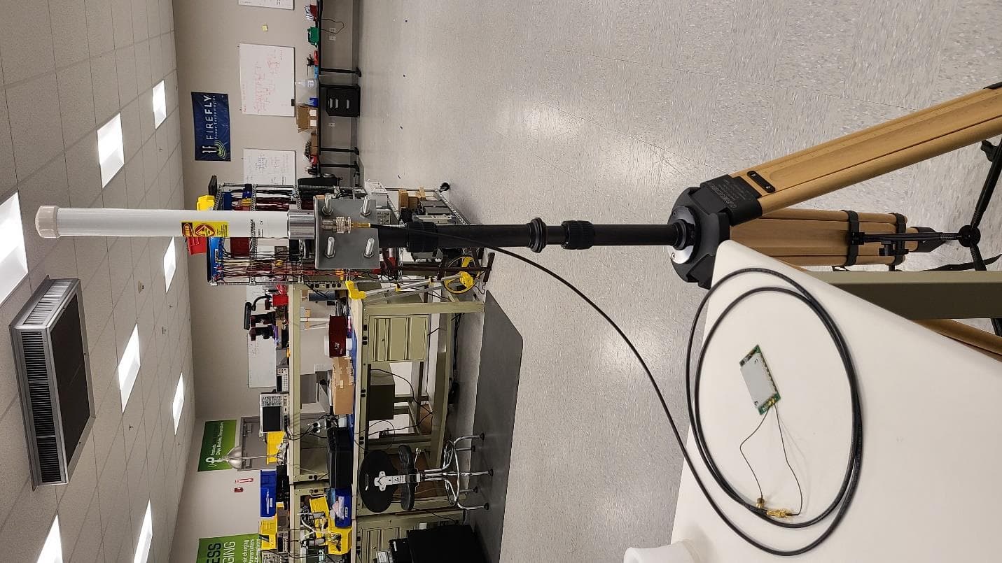
Click to zoom
Application Details
- Equipment Class
- DSS - Part 15 Spread Spectrum Transmitter
- Date of Grant
- Apr 23, 2023
- Application Purpose
- Original Equipment
- Date of Application
- Apr 10, 2023
- Equipment Note
- PCR91502-M Rain RFID Module
- Frequency Range
- 902.75000000 - 927.25000000
- Company
- Powercast Corporation
- Country
- United States
Documents & Files
Document Text
Text extracted from the exhibit documents filed with the FCC. Open a document above to read the original.
Users Manual
User Manual PCR91502-M Powercast RAIN RFID Reader Module Powercast products and technology are covered by one or more patents with other patents pending. All patent and trademark information can be found at http://www.powercastco.com/IP/. Rev 1– 2023/01 User’s Manual – PCR91502-M Module Page 1 www.powercastco.com PRODUCT DESCRIPTION The Powercast PCR91502-M is a RAIN UHF RFID Reader module. The module is intended to be integrated into other electronic product designs in order to enable RAIN RFID functionality. The reader module’s air interface protocol adheres to EPCglobal® UHF Class 1 Gen 2 / ISO 18000- 63 RFID. It is designed to interface to other embedded electronics systems via USB or UART communication lines and is powered from externally applied 5V DC power. The RFID module communicates with and powers RFID tag devices. A Gen2 compliant tag device communicates back to the reader via RF backscattering. The reader operates in the 902-928MHz ISM frequency band. Operational power as well as communication is provided to the reader using header J5. The module can support up to 4 antennas via U.FL/UMCC connectors at ports J1 through J4. The PCR91502-M module has on board LEDs to display status of the reader and tag devices. ORDERING OPTIONS Part Number PCR91502-M PRODUCT CONTENTS The following items are included: Qty Description 1 PCR91502-M RAIN RFID Reader Module APPLICATIONS • Communicate with and power Gen2 compliant RFID tags o Active tags o Battery-Assisted-Passive tags o Passive tags • Inventory tags in a given location • Issue access (read, write, etc.) commands to tags User Manual PCR91502-M Powercast RAIN RFID Reader Module Powercast products and technology are covered by one or more patents with other patents pending. All patent and trademark information can be found at http://www.powercastco.com/IP/. Rev 1– 2023/01 User’s Manual – PCR91502-M Module Page 2 www.powercastco.com SET-UP AND OPERATION 1. Mount the module in the desired location with appropriate connection to a heat sink. 2. Make the appropriate connections to header J5 for 5V power and USB or UART communication. 3. Determine whether using USB based serial communication or direct UART communication. a. USB – have jumper in place on header J6 b. Direct UART – remove jumper from header J6 4. Utilize the binary protocol to control the module. J5 Pin Number Signal Description 1 5V_USB_CONN Attach 5V DC power 2 GND Ground 3 5V_USB_CONN Attach 5V DC power 4 GND Ground 5 D_P USB communication Data Positive 6 D_N USB Communication Data Negative 7 uP_RTS UART 1 Request to Send line. Connect to host RTS line. 8 uP_CTS UART 1 Clear to Send line. Connect to host CTS line. 9 uP_TXD UART 1 TX line. Connect to host RX line. 10 uP_RXD UART 1 RX line. Connect to host TX line. 11 VDD_Ex10 Internally used 3.3V power rail. Do Not Connect. 12 GND Ground 13 U2TX UART 2 TX line. Used for debugging only 14 U2RX UART 2 TX line. Used for debugging only. User Manual PCR91502-M Powercast RAIN RFID Reader Module Powercast products and technology are covered by one or more patents with other patents pending. All patent and trademark information can be found at http://www.powercastco.com/IP/. Rev 1– 2023/01 User’s Manual – PCR91502-M Module Page 3 www.powercastco.com The status LED D3 indicates the following operating conditions: D3 LED Status Description Off Device is not Powered Solid Red Firmware Mismatch Blinking Red Over Temperature Condition Green Reader Idle Blue Reader Non-Idle Normal Operation – Tag Read / Inventory Yellow Reader Non-Idle Test Mode – CW, PRBS, Etc. CONTROLLING THE READER 1. Connect the RFID Reader module to a PC or other communication device using the appropriate power and communication connections on header J5. 2. Connect an antenna to an RF output port (J1-J4). 3. Use the following baud rate settings: a. Speed: 115200 b. Data: 8 bit c. Parity: None d. Stop bits: 1 bit e. Flow control: none 4. Utilize the reader modules binary protocol API document to communicate and control the reader module. SPECIFICATIONS Item Description Frequency Frequency Hopping: 902.75MHz to 927.25MHz; 914.25 MHz Center Frequency RF Communication EPCglobal® UHF Class 1 Gen 2 / ISO 18000-63 RFID Power output 0 to +30dBm Interface USB Port Serial Communication or Direct Serial UART Operating Temperature -40°C to +85°C Environment Indoor or outdoor use with appropriate enclosure Mounting Mount to heat sink with non-conductive thermal insulator Power 5VDC/2A through USB-C Port Dimensions 2.7” × 1.7” × 0.5” Note: The PCR91502-M is EPC Gen 2 Compliant SUPPORT User Manual PCR91502-M Powercast RAIN RFID Reader Module Powercast products and technology are covered by one or more patents with other patents pending. All patent and trademark information can be found at http://www.powercastco.com/IP/. Rev 1– 2023/01 User’s Manual – PCR91502-M Module Page 4 www.powercastco.com Technical support for Powercast products can be initiated through the following methods: Website contact form: http://www.powercastco.com/contact/ Telephone: +1 412-455-5800 COMPLIANCE STATEMENTS This device complies with part 15 of the FCC Rules. Operation is subject to the following two conditions: (1) This device may not cause harmful interference, and (2) this device must accept any interference received, including interference that may cause undesired operation. Changes or modifications not expressly approved by Powercast could void the user’s authority to operate the equipment. Use and maintain device only as specified in this manual. This equipment has been tested and found to comply with the limits for a Class B digital device, pursuant to Part 15 of the FCC Rules. These limits are designed to provide reasonable protection against harmful interference in a residential installation. This equipment generates, uses, and can radiate radio frequency energy and, if not installed and used in accordance with the instructions, may cause harmful interference to radio communications. However…
Text truncated - open the document above for the full version.
Users Manual
PCR91502-M Host System Integration Description FCC ID: YESPCR91502-M Powercast Corporation Introduction The PCR91502-M is a UHF RAIN RFID Reader module intended to be integrated into other host systems. The Powercast PCR91502-M RAIN RFID Reader module will operate as a frequency hopping device under FCC 15.247. The device is designed to comply with FCC 15.247 by using frequency hopping. The reader module’s air interface protocol adheres to EPCglobal® UHF Class 1 Gen 2 / ISO 18000-63 RFID. Host System Integration Description The PCR91502-M device is intended to be integrated into a host system. The host system may include a processor that communicates with and controls the PCR91502-M RFID module. RF connections from the PCR91502-M RFID module may be brought out to the external sides of the host system enclosure. Installation Details The host system is anticipated to be a fixed (permanently located with an antenna that’s affixed to a structure so that it can’t be easily relocated) system installed in a server room style environment. One or more antennas shall be connected via cables from the host system enclosure. RFID tag devices in the operating environment will communicate back with the reader module by passively backscattering the received RF. Installation of the host system devices is performed by professionals and is supervised by Powercast personnel . Antenna 1 Port Antenna 2 Port Antenna 3 Port Antenna 4 Port PCR91502 - M RFID Module Host System Processor Host System Enclosure Host System Power + Communicatio n
Cover Letter(s)
620 Alpha Drive • Pittsburgh, PA 15238 • +1 412-455-5800 Professional Installation Attestation Date: 1/25/2022 FCC ID: YESPCR91502-M Powercast declares the requirements are met for KDB 353028 D01 v01 for the above- mentioned product device IDs per the details below. This device must be professionally installed. Professional Installation permits the use of the following antennas specified below. Antenna Type Manufacturer Part Number Max Gain Circular Patch Laird PAR90209H 9 dBic = 6dBi Linear Patch Powercast AP-ANT-H1-915 6 dBi Linear Pasternack PE51OM1013 3 dBi Qualified Cables and Adaptors Type Manufacturer Part Number Loss at 900MHz LMR-100 Pasternack LMR-100 22.8 dB/100ft RF Adaptor – SMA Plug, Male Pin to RP-TNC Jack, Male Pin Amphenol RF 242124RP 0.1 dB RF Adaptor – U.FL (UMCC, IPEX) Female to SMA Female Adam Tech CA-DKCA1- 152L0-AJI0 1 dB NOTE: Only similar antennas with the same or lower gain, and cables with/without additional adapters or connectors with total loss same as or higher than the total loss in the table above can be used to connect to the PCR91502-M without violating FCC regulations. It is the responsibility of the professional installers to comply with this requirement. 1. The device referred to in the above IDs is not sold through retail chains or public stores. It is only sold directly to known, qualified users or through Value Added Reseller Partners who are authorized installers or resellers. 2. The device referred to in the above IDs is not sold via retail or to the general public. It is only sold to known, qualified users or through Value Added Reseller Partners who are authorized installers or resellers. 3. The PCR91502-M is an embedded RFID module for Advanced Industrial devices. It is usually part of a larger industrial system. It is not sold to the general public. 4. The device referred to in the above IDs is an embedded RFID reader typically used as part of a larger Advanced Industrial System, such as an inventory tracking system. Operation of these larger systems requires specific equipment knowledge of configuration of multiple hardware points including RFID tags and RFID antennas. These require installation by an experienced or trained professional. 5. Installation will be controlled by the known, qualified users or Value-Added Reseller Partners who have knowledge of installation requirements. Installation requirements include knowledge of RFID systems including hardware, software, and system integration. Hardware includes placement and orientation of antennas and RFID tags. Software includes operation of the software programming interface. System integration includes positioning, orientation, and distance of the various hardware components including antennas and tags. 6. This product is only sold to known, qualified users or through Value Added Reseller Partners who are either trained professionals or hire knowledgeable, trained installers. It is not sold to the general public. 7. Installation requires special training related to the software programming interface, knowledge of RFID antenna installation, connector cables with specialty connectors, and RFID tags. Eric Biel Director of Strategic Partnerships
Cover Letter(s)
620 Alpha Drive • Pittsburgh, PA 15238 • +1 412-455-5800 Modular Approval Exhibit Date: 1/23/2022 FCC ID: YESPCR91502-M § 15.212 Modular transmitters. (a) Single modular transmitters consist of a completely self-contained radiofrequency transmitter device that is typically incorporated into another product, host or device. Split modular transmitters consist of two components: a radio front end with antenna (or radio devices) and a transmitter control element (or specific hardware on which the software that controls the radio operation resides). All single or split modular transmitters are approved with an antenna. All of the following requirements apply, except as provided in paragraph (b) of this section. (1) Single modular transmitters must meet the following requirements to obtain a modular transmitter approval. (i) The radio elements of the modular transmitter must have their own shielding. The physical crystal and tuning capacitors may be located external to the shielded radio elements. - Powercast asserts that the radio elements of the modular transmitter PCR91502-M have their own shielding. (ii) The modular transmitter must have buffered modulation/data inputs (if such inputs are provided) to ensure that the module will comply with part 15 requirements under conditions of excessive data rates or over-modulation. - Powercast asserts that the modular transmitter has buffered modulation / data inputs. (iii) The modular transmitter must have its own power supply regulation. - Powercast asserts that the modular transmitter its own power supply regulation. (iv) The modular transmitter must comply with the antenna and transmission system requirements of §§ 15.203, 15.204(b) and 15.204(c). The antenna must either be permanently attached or employ a “unique” antenna coupler (at all connections between the module and the antenna, including the cable). The “professional installation” provision of § 15.203 is not applicable to modules but can apply to limited modular approvals under paragraph (b) of this section. - -Powercast asserts that the modular transmitter employs unique antenna connectors and complies with the antenna and transmission system requirements of 15.203, 15.204 (b) and 15.204 (c). (v) The modular transmitter must be tested in a stand-alone configuration, i.e., the module must not be inside another device during testing for compliance with part 15 requirements. Unless the transmitter module will be battery powered, it must comply with the AC line conducted requirements found in § 15.207. AC or DC power lines and data input/output lines connected to the module must not contain ferrites, unless they will be marketed with the module (see § 15.27(a)). The length of these lines shall be the length typical of actual use or, if that length is unknown, at least 10 centimeters to insure that there is no coupling between the case of the module and supporting equipment. Any accessories, peripherals, or support equipment connected to the module during testing shall be unmodified and commercially available (see § 15.31(i)). - Powercast asserts that the module was tested in stand-alone configuration. All peripherals used during testing are commercially available. (vi) The modular transmitter must be equipped with either a permanently affixed label or must be capable of electronically displaying its FCC identification number. - Powercast asserts that the module will be equipped with a permanently affixed label. (A) If using a permanently affixed label, the modular transmitter must be labeled with its own FCC identification number, and, if the FCC identification number is not visible when the module is installed inside another device, then the outside of the device into which the module is installed must also display a label referring to the enclosed module. This exterior label can use wording such as the following: “Contains Transmitter Module FCC ID: XYZMODEL1” or “Contains FCC ID: XYZMODEL1.” Any similar wording that expresses the same meaning may be used. The Grantee may either provide such a label, an example of which must be included in the application for equipment authorization, or, must provide adequate instructions along with the module which explain this requirement. In the latter case, a copy of these instructions must be included in the application for equipment authorization. - Powercast asserts that the modular transmitter will be labeled with it’s own FCC ID and if the module is integrated into a product and the FCC ID is not visible that product will display a label referring to the enclosed module. (B) If the modular transmitter uses an electronic display of the FCC identification number, the information must be readily accessible and visible on the modular transmitter or on the device in which it is installed. If the module is installed inside another device, then the outside of the device into which the module is installed must display a label referring to the enclosed module. This exterior label can use wording such as the following: “Contains FCC certified transmitter module(s).” Any similar wording that expresses the same meaning may be used. The user manual must include instructions on how to access the electronic display. A copy of these instructions must be included in the application for equipment authorization. - The modular transmitter does not use an electronic display of its FCC identification number (vii) The modular transmitter must comply with any specific rules or operating requirements that ordinarily apply to a complete transmitter and the manufacturer must provide adequate instructions along with the module to explain any such requirements. A copy of these instructions must be included in the application for equipment authorization. - Powercast asserts that the modular transmitter will comply with any specific rules or operating requirements that ordinarily apply to a complete transmitter and will provide adequate instructions along with the module to ex…
Text truncated - open the document above for the full version.
External Photos
PCR91502-M External Photos FCC ID: YESPCR91502-M Powercast Corporation Powercast PAP-ANT-H1-915, linearly polarized patch antenna, gain = 6 dBi Laird PAR90209H, circularly polarized panel antenna, gain = 9 dBic = 6 dBi Pasternack PE51OM1013, omnidirectional dipole antenna, gain = 3dBi
ID Label/Location Info
PCR91502-M This device complies with part 15 of the FCC Rules. Operation is subject to the following two conditions: (1) this device may not cause harmful interference, and (2) this device must accept any interference received, including interference that may cause undesired operation. FCCID:YESPCR91502-M INPUT: 5V DC/2A
Internal Photos
PCR91502-M Internal Photos FCC ID: YESPCR91502-M Powercast Corporation
RF Exposure Info
MPE TEST REPORT for the POWERCAST CORPORATION FCC ID: YESPCR91502-M WLL REPORT# 18025-01 REV 0 Prepared for: Powercast Corporation 620 Alpha Drive Pittsburgh, Pennsylvania 15238 Prepared By: Washington Laboratories, Ltd. 4840 Winchester Boulevard Frederick, Maryland 21703 Testing Certificate AT-1448 Certificates and reports shall not be reproduced except in full, without the written permission of Washington Laboratories, Ltd Powercast Corporation PCR91502-M MPE Test Report WLL Report 18025-01 Rev 0 Page-2 of 11 MPE Test Report for the Powercast Corporation PCR91502-M FCC ID: YESPCR91502-M March 1, 2023 WLL Report# 18025-01 Rev 0 Prepared by: ___________________________ Ryan Mascaro RF Test Engineer Reviewed by: ____________________________ Steven D. Koster President Powercast Corporation PCR91502-M MPE Test Report WLL Report 18025-01 Rev 0 Page-3 of 11 Abstract This report has been prepared on behalf of Powercast Corporation to document the findings of the maximum permissible exposure evaluation on the Powercast Corporation PCR91502-M. The information provided on this report is only applicable to device herein documented, as the EUT. The purpose of this evaluation is to establish a minimum safe distance as per the RF exposure requirements as defined in FCC §1.1307 & §1.1310. This report documents the results of testing to the requirements of: • CFR Title 47 Volume 1 Practice and Procedure; (1.1307) Environmental Assessments The Evaluation was performed by Washington Laboratories, Ltd, 4840 Winchester Blvd., Suite 5, Frederick, MD 21703. Washington Laboratories, Ltd. has been accepted as an EMC Conformity Assessment Body (CAB) under the United States/European Union Memorandum of Agreement. Washington Laboratories, Ltd. has been accepted by the FCC and approved by ANAB under Testing Certificate AT-1448 as an independent FCC test laboratory. Revision History Description of Change Date Rev 0 Initial Release March 1, 2023 Powercast Corporation PCR91502-M MPE Test Report WLL Report 18025-01 Rev 0 Page-4 of 11 Table of Contents Abstract ...................................................................................................................................................... iii Table of Contents ....................................................................................................................................... iv List of Tables ...............................................................................................................................................v 1 Introduction ......................................................................................................................................6 2 Requirements ...................................................................................................................................6 Transmitter Categories ................................................................................................................ 6 2.1.1 Fixed Installations ................................................................................................................... 6 2.1.2 Mobile Devices ....................................................................................................................... 6 2.1.3 Portable Devices ..................................................................................................................... 7 Exposure Categories ................................................................................................................... 7 2.2.1 Occupational/Controlled Exposure ......................................................................................... 7 2.2.2 General Population/Uncontrolled Exposure ........................................................................... 7 3 Device Summary ..............................................................................................................................9 4 Radio Frequency Radiation Exposure Evaluation .........................................................................10 Powercast Corporation PCR91502-M MPE Test Report WLL Report 18025-01 Rev 0 Page-5 of 11 List of Tables Table 1: MPE Limits (FCC) ....................................................................................................................... 8 Table 2: Device Summary – PCR91502-M ................................................................................................ 9 Table 3: Transmitter MPE Calculation Summary (FCC) ......................................................................... 11 Powercast Corporation PCR91502-M MPE Test Report WLL Report 18025-01 Rev 0 Page-6 of 11 1 Introduction This report has been prepared on behalf of Powercast Corporation for the PCR91502-M to show compliance with the RF exposure requirements as defined in FCC §1.1307 & §1.1310. The testing in-support of this evaluation was performed at Washington Laboratories, Ltd, 4840 Winchester Blvd., Frederick, MD 21703. Washington Laboratories, Ltd. has been accepted as an EMC Conformity Assessment Body (CAB) under the United States/European Union Memorandum of Agreement. Washington Laboratories, Ltd. is accredited with ANAB under Testing Certificate AT-1448. 2 Requirements Transmitter Categories 2.1.1 Fixed Installations A fixed location means that the device, including its antenna, is physically secured at a permanent location and is not able to be easily moved to another location. Additionally, distance to humans from the antenna is maintained to at least 2 meters. 2.1.2 Mobile Devices A mobile device is defined as a transmitting device designed to be used in other than fixed locations and to be generally used in such a way that a separation distance of at least 20 centimeters is normally maintained between the transmitter's radiating structures and the body of the user or nearby persons. Transmitters designed to be used by consumers or workers that can be easily re-located, such as a wireless modem opera…
Text truncated - open the document above for the full version.
Test Report
FCC CERTIFICATION TEST REPORT for the POWERCAST CORPORATION FCC ID: YESPCR91502-M WLL REPORT# 18024-01 REV 2 Prepared for: Powercast Corporation 620 Alpha Drive Pittsburgh, Pennsylvania 15238 Prepared By: Washington Laboratories, Ltd. 4840 Winchester Boulevard. STE# 5 Frederick, Maryland 21703 Testing Certificate AT-1448 Certificates and reports shall not be reproduced except in full, without the written permission of Washington Laboratories, Ltd Powercast Corporation PCR91502-M FCC Certification Test Report WLL Report 18024-01 Rev 0 Page-2 of 51 FCC Certification Test Report for the Powercast Corporation PCR91502-M FCC ID: YESPCR91502-M March 2, 2023 WLL Report# 18024-01 Rev 2 Prepared by: ___________________________ Samuel B. Violette Vice President Reviewed by: ____________________________ Steve Koster President Powercast Corporation PCR91502-M FCC Certification Test Report WLL Report 18024-01 Rev 0 Page-3 of 51 Abstract This report has been prepared on behalf of Powercast Corporation to support the attached Application for Equipment Authorization. The test report and application are submitted for a Frequency Hopping Spread Spectrum (FHSS) Transmitter under Part 15.247 of the FCC Rules. This Certification Test Report documents the test configuration and test results for the Powercast Corporation PCR91502-M. The information provided in this report is only applicable to device herein documented, as the EUT. Final (worst-case) radiated emissions testing was performed in the Free-space Anechoic Chamber Test- site (FACT) 3m Chamber of Washington Laboratories, Ltd., located at 4840 Winchester Boulevard, Suite #5, Frederick, MD 21703. Other investigations of radiated emissions were performed on the 3-meter Open Area Test Site (OATS) Site description and site attenuation data have been placed on file with the FCC's Sampling and Measurements Branch at the FCC laboratory in Columbia, MD. The Powercast Corporation PCR91502-M complies with the requirements for a Frequency Hopping Spread Spectrum (FHSS) Transmitter device under FCC Part 15.247. Revision History Description of Change Date Rev 0 Initial Release March 2, 2023 Rev 1 TCB Comments, Dated: 3/21/2023 March 31, 2023 Rev 2 TCB Comments, Dated: 4/10/2023 April 11, 2023 Powercast Corporation PCR91502-M FCC Certification Test Report WLL Report 18024-01 Rev 0 Page-4 of 51 Table of Contents Abstract ...................................................................................................................................................... iii Table of Contents ....................................................................................................................................... iv List of Tables .............................................................................................................................................. v List of Figures ............................................................................................................................................ vi 1 Introduction ..................................................................................................................................... 7 Compliance Statement ................................................................................................................ 7 Test Scope ................................................................................................................................... 7 Contract Information ................................................................................................................... 7 Test and Support Personnel ........................................................................................................ 7 Deviations to the Standard .......................................................................................................... 7 2 Equipment Under Test .................................................................................................................... 8 EUT Identification & Description .............................................................................................. 8 Test Configuration ...................................................................................................................... 9 Support Equipment ..................................................................................................................... 9 Interface Cables .......................................................................................................................... 9 Testing Algorithm ..................................................................................................................... 11 Test Location ............................................................................................................................ 11 Deviations to the Standard ........................................................................................................ 11 Measurements ........................................................................................................................... 12 2.8.1 References ............................................................................................................................. 12 Measurement Uncertainty ......................................................................................................... 12 3 Test Equipment ............................................................................................................................. 14 4 Test Results ................................................................................................................................... 15 Time of Occupancy ................................................................................................................... 16 RF Power Output: (FCC Part 15.27 (b)(2)(4)).......................................................................... 19 Occupied Bandwidth: (FCC Part §2.1049) .......................…
Text truncated - open the document above for the full version.
Test Report
Linear Polarity RFID Patch Antenna PAP-ANT-H1-915 Specifications Antenna Part Number PAP-ANT-H1-915 Frequency Range 902 – 928 MHz Gain 6 dBi 3 dB Beamwidth – Azimuth 66° 3 dB Beamwidth – Elevation 126° Front to Back Ratio 25 dB Polarization Linear (Horizontal) Input Impedance 50 Ohms Mechanical Size 8.90’’ x 3.23’’ x 0.88’’ (226mm x 82mm x 20mm) Antenna Connection Fixed, SMA Female Environmental Rating IP XX
Test Report
1 - Pasternack does not make Features • Superior all weather performance • Rugged industrial grade design • Lightweight fiberglass radome • Integral N-Female connector • H…
Text truncated - open the document above for the full version.
Contact Information
Applicant
Charles Greene(CTO)
Test Firm
Washington Laboratories, Ltd.Steve Koster
Technical Specifications
| # | Rule Parts | Frequency Range | Power Output |
|---|---|---|---|
| 1 | 15C | 902.75 MHz - 927.25 MHz | 955.00 mW |
Other Applications from Powercast Corporation
YESPCR91501
Dec 29, 2022PCR91501 RFID Reader
Equipment Class
DSS - Part 15 Spread Spectrum Transmitter
YESWCG91501
Feb 11, 2020Wireless Charging Grip
Equipment Class
DTS - Digital Transmission System
YESTX91501
Sep 29, 2010RF Powering Device
Equipment Class
DTS - Digital Transmission System