YESTX91501RF Powering Device
Powercast Corporation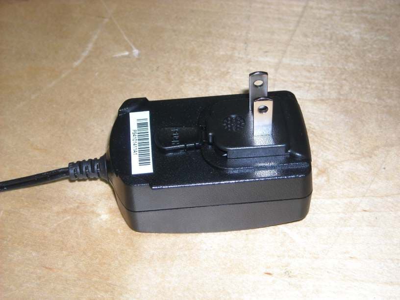
Click to zoom
Application Details
- Equipment Class
- DTS - Digital Transmission System
- Date of Grant
- Sep 29, 2010
- Application Purpose
- Original Equipment
- Date of Application
- Sep 29, 2010
- Equipment Note
- RF Powering Device
- Frequency Range
- 915.00000000 - 915.00000000
- Company
- Powercast Corporation
- Country
- United States
Documents & Files
Document Text
Text extracted from the exhibit documents filed with the FCC. Open a document above to read the original.
Users Manual
Product Manual TX91501 – 915 MHz Powercaster TM Transmitter Rev A – 2010/08 Users Manual - TX91501 Transmitter Page 1 www.powercastco.com PRODUCT DESCRIPTION The Powercast TX91501 Powercaster transmitter is specially designed to provide both power and data to end devices containing the Powercast P2110 or P1110 Powerharvester® receivers. The TX91501 is housed in a durable plastic case with several mounting options. Operational power is provided to either of the two DC power connectors at 5V DC. The TX91501 includes a status LED to provide feedback on functional state. The TX91501 has a factory set, fixed power output and no user- adjustable settings. The label indicates the effective power for which the device is configured, with 3 watts EIRP being the maximum. Once properly mounted, transmission is initiated by applying power to the TX91501. FEATURES FCC and IC approved Flexible wall mounting options Fully integrated system Transmits power and data Factory configurable for custom applications Wide temperature range RoHS compliant POWERING APPLICATIONS Battery-free wireless sensors - Industrial Monitoring - Smart Grid - Structural Health Monitoring - Defense - Building automation - Agriculture - Oil & Gas - Location-aware services Wireless trigger Low power electronics ORDERING OPTIONS PRODUCT CONTENTS The following items are included inside the package: Qty Description 1 915 MHz transmitter 1 Power supply 1 US plug for Power supply (must be snapped in to the Power supply) 1 Instruction card Powercast®, Lifetime Power®, Powerharvester®, and Powercaster™ are registered trademarks of Powercast Corporation. All other trademarks are the property of their respective owners. Product Manual TX91501 – 915 MHz Powercaster TM Transmitter Rev A – 2010/08 Users Manual - TX91501 Transmitter Page 2 www.powercastco.com SET-UP AND OPERATION 1. Wall-mount the TX91501 in the desired location with the Powercast logo and status LED facing the direction in which the energy is desired. For permanent installations, mount the TX91501 eight feet or more above floor level. 2. Plug the DC connector of the power supply into one of the two available connectors on the TX91501. Plug the power supply into a 120V outlet. 3. When the green LED illuminates, the TX91501 is active and transmitting radio frequency (RF) energy. Data is automatically included in the transmission and can be received by one of Powercast’s Powerharvester Modules. The status LED indicates the following operating conditions: LED Status Description Off Off 5VDC is not applied Green Active Transmitting normally Red 1 Fault Transmission stopped due to an obstruction in close proximity 2 1 During fault status, the LED will momentarily blink about once per second until the obstruction is removed. 2 If operating on a flat surface for testing purposes, such as a table, it is recommended that the TX91501 is elevated off the surface with a non- conducting material, such as foam or a cardboard box, OR the TX91501 is slid to the edge for unobstructed transmission. SPECIFICATIONS Item Description Modulation Direct Sequence Spread Spectrum (DSSS) Amplitude Shift Keying (ASK) Frequency 915 MHz Center Frequency Power output (not user adjustable) TX91501-3W-XX: 3 watt EIRP TX91501-1W-XX: 1 watts EIRP Beam pattern 60° width 60° height Vertical Polarization Approvals FCC Part 15.247 Industry Canada Firmware Version Located on the TX91501 label Data Communications An 8-bit, factory-set, TX91501 identification (ID) number is broadcast with random intervals up to 10ms using Amplitude Shift Keying (ASK) modulation. The ID number can be found on the TX91501 label. Operating Temperature -20°C to 50°C Installation Environment Indoor use only Mounting 6 bracket mounting holes (See mechanical drawing for dimensions) 2 keyholes (See mechanical drawing for dimensions) Power 5VDC/1A through included Power Supply Color Black Dimensions 6.75” x 6.25” x 1.63” (171.45 x 158.75 x 41.4 mm) Weight 1 lb Warranty 1 year Product Manual TX91501 – 915 MHz Powercaster TM Transmitter Rev A – 2010/08 Users Manual - TX91501 Transmitter Page 3 www.powercastco.com MECHANICAL (REAR VIEW) *Dimensions in inches Product Manual TX91501 – 915 MHz Powercaster TM Transmitter Rev A – 2010/08 Users Manual - TX91501 Transmitter Page 4 www.powercastco.com ACCESSORIES The power supply included with the TX91501 supports interchangeable wall plugs. The power supply ships with the US plug adapter. Power supply: PSAC05R-050(P)-R US plug adapter: RPA-R UK plug adapter: RPK-N-R EU plug adapter: RPE-N-R 4-plug Kit: RPBAG-R Mounting Brackets: http://www.polycase.com/category/nema-mounting-flange-kit.html or equivalent SUPPORT Technical support for Powercast products can be initiated through the following methods: Website contact form: http://www.powercastco.com/contact/ Telephone: +1 724-238-3700 Product Manual TX91501 – 915 MHz Powercaster TM Transmitter Rev A – 2010/08 Users Manual - TX91501 Transmitter Page 5 www.powercastco.com COMPLIANCE STATEMENTS This device is intended for commercial and industrial applications. Changes or modifications not expressly approved by Powercast could void the user’s authority to operate the equipment. Use and maintain device only as specified in this manual. This equipment has been tested and found to comply with the limits for a Class B digital device, pursuant to Part 15 of the FCC Rules. These limits are designed to provide reasonable protection against harmful interference in a residential installation. This equipment generates, uses, and can radiate radio frequency energy and, if not installed and used in accordance with the instructions, may cause harmful interference to radio communications. However, there is no guarantee that interference will not occur in a particular installation. If this equipment does cause harmful interference to radio or television reception, which can be determined by turning the equipment off and on, the user is encouraged to try to correct the inte…
Text truncated - open the document above for the full version.
Cover Letter(s)
Mairaj, Below is the response I received from the FCC this morning showing the device is acceptable for filing under 15.247. Please let me know if you have questions. Thanks. Charles Greene, Ph.D. Chief Technical Officer Powercast Corporation 566 Alpha Drive Pittsburgh, PA 15238 724.238.3700 ext. 4077 www.powercastco.com This e-mail and any attachments are intended exclusively for the person(s) named above and may contain information that is legally privileged and confidential. If you are not the intended recipient, please note that any disclosure, retention or use of this e-mail or any attachments is strictly prohibited and may be unlawful. If you have received this e-mail in error, please notify the sender and delete the email and all attachments from your system. Thank you. From: [email protected] [mailto:[email protected]] Sent: Wednesday, September 22, 2010 10:55 AM To: [email protected] Subject: Response to Inquiry to FCC (Tracking Number 670528) FCC Home | Search | RSS | Updates | E-Filing | Initiatives | Consumers | Find People Office of Engineering and Technology Inquiry: Please see the attached document requested by Joe Dichoso. Response: The attached description of the device is acceptable for filing under the DTS rules in Section 15.247 with appropriate conditions as indicated in the attachment. In addition, note that any end devices must not be marketed for use with the transmitter unless it properly receives and extracts the data from this device. Do not reply to this message. Please select the Reply to an Inquiry Response link from the OET Inquiry System to add any additional information pertaining to this inquiry.
External Photos
EK0196-1 External Photographs Powercast Corporation EK0196-1 External Photographs Powercast Corporation EK0196-1 External Photographs Powercast Corporation
ID Label/Location Info
TX91501 FCC ID: YESTX91501IC: 8985A-TX91501 Powercaster™ Transmitter – 915 MHz Powercast Transmitter Label 2” Certification numbers FCC Compliance statementModel number This device complies with Part 15 of the FCC Rules. Operation is subject to the following two condition s: (1) this device may not cause harmful interference, and (2) this device must accept any interference received, including interference that may cause undesired operation.INPUT: 5VDC/1A 2” undesired operation.
Internal Photos
EK0196-1 External Photographs Powercast Corporation EK0196-1 External Photographs Powercast Corporation EK0196-1 External Photographs Powercast Corporation EK0196-1 External Photographs Powercast Corporation EK0196-1 External Photographs Powercast Corporation EK0196-1 External Photographs Powercast Corporation EK0196-1 External Photographs Powercast Corporation EK0196-1 External Photographs Powercast Corporation EK0196-1 External Photographs Powercast Corporation EK0196-1 External Photographs Powercast Corporation
RF Exposure Info
Prediction of MPE limit at a given distance Equation from page 18 of OET Bulletin 65, Edition 97-01 where:S = power density P = power input to the antenna G = power gain of the antenna in the direction of interest relative to an isotropic radiator R = distance to the center of radiation of the antenna Maximum peak output power at the antenna terminal: 26.30(dBm) Maximum peak output power at the antenna terminal: 426.5795188(mW) Antenna gain(typical): 8.343(dBi) Maximum antenna gain: 6.828101998(numeric) Prediction distance: 20(cm) Prediction frequency: 915(MHz) MPE limit for uncontrolled exposure at prediction frequency: 0.61(mW/cm^2) Power density at prediction frequency:0.579469(mW/cm^2) 2 4R PG S π =
Test Report
Curtis-Straus LLC is accredited by the American Association for Laboratory Accreditation for the specific scope of accreditation under Certificate Number 1627-01. This report may contain data which is not covered by the A2LA accreditation. ____________________________________________________________ Curtis-Straus LLC, a wholly owned subsidiary of BV CPS One Distribution Center Circle, #1 • •• • Littleton, MA • •• • TEL (978) 486-8880 • •• • FAX (978) 486-8828 page 1 of 32 Test Report Curtis-Straus LLC, a wholly owned subsidiary of BV CPS Report No EK0169-1 Client Powercast Corporation Address 566 Alpha Drive Pittsburgh, PA 15238 Phone 412-436-4077 Items tested Powercast Transmitter FCC ID YESTX91501 IC ID 8985A-TX91501 FRN 0019814789 Equipment Type DSS Equipment Code Digital Spread Spectrum Transmitter FCC/IC Rule Parts 47 CFR 15.247, RSS 210 issue 7 and RSS GEN issue 2 Test Dates May 14, 2010 & July 6, 2010 Results As detailed within this report Prepared by Matthew Burman – Test Engineer Authorized by Mairaj Hussain – EMC Supervisor Issue Date 9/23/2010 Conditions of Issue This Test Report is issued subject to the conditions stated in the ‘Conditions of Testing’ section on page 31 of this report. Test Report for Powercast Corporation • •• • Report No. EK0169-1 September 28, 2010 ______________________________________________________________________ ____________________________________________________________ Curtis-Straus LLC, a wholly owned subsidiary of BV CPS One Distribution Center Circle, #1 • •• • Littleton, MA • •• • TEL (978) 486-8880 • FAX (978) 486-8828 page 2 of 32 Contents Contents..................................................................................................................................2 Summary.................................................................................................................................3 Test Methodology ....................................................................................................................3 Product Tested - Configuration Documentation .......................................................................4 Statement of Conformity......................................................................................................5 Test Results ............................................................................................................................6 Bandwidth............................................................................................................................6 Peak Power.........................................................................................................................8 Band Edge Measurements.................................................................................................12 Radiated Spurious Emissions............................................................................................15 Conducted Spurious Emissions.........................................................................................16 Power Spectral Density......................................................................................................20 Voltage Variations..............................................................................................................25 Occupied Bandwidth..........................................................................................................26 Measurement Uncertainty......................................................................................................28 Test Equipment Used ............................................................................................................29 Product Documentation .........................................................................................................30 Conditions Of Testing ............................................................................................................31 Form Final Report REV 7-20-07 (DW) Test Report for Powercast Corporation • •• • Report No. EK0169-1 September 28, 2010 ______________________________________________________________________ Release Control Record Issue No. Reason for change Date Issued 1 Original Release September 28, 2010 _____________________________________________________________ Curtis-Straus LLC, a wholly owned subsidiary of BV CPS One Distribution Center Circle, #1 • •• • Littleton, MA • •• • TEL (978) 486-8880 • •• • FAX (978) 486-8828 page 3 of 32 Summary This test report supports an application for certification of a transmitter operating pursuant to 47 CFR 15.247 and RSS-210. The product is the Powercast Transmitter. It is a transmitter that operates in the range 902-928MHz. We found that the product met the above requirements without modification. The test sample was received in good condition. The EUT does not have a receive mode. Test Methodology Radiated emission and AC Line conducted testing for 47 CFR Part 15.247 compliance was performed according to FCC test procedure for DTS published March 23, 2005. Radiated Emissions were maximized by rotating the device around three orthogonal axes as well as varying the test antenna’s height and polarity. The device antenna cannot be maximized separately. The EUT is an intentional radiator that sends data and power to nearby devices. The EUT can send commands and identification data. The RF signal produced by EUT is DSSS with a fixed center frequency of 915MHz, and data is included by the EUT using ASK modulation. The maximum data rate is 16.67kbps. The EUT has a factory programmable data rate and power level, and it is not user adjustable. The EUT was tested at the minimum (no data), mid (8.33kbps), and maximum (16.67kbps) data rates and at the minimum and maximum power setting Conducted emission at the antenna port was performed, as required by rule section. No duty cycle correction factor was needed, therefore it was not measured The EUT operating voltage is 5Vdc through an AC/DC power supp…
Text truncated - open the document above for the full version.
Test Setup Photos
EK0196-1 Test Setup Photographs Powercast Corporation Conductive Measurements AC Line Conducted Measurements – Front – Wall Mount EK0196-1 Test Setup Photographs Powercast Corporation AC Line Conducted Measurements – Front – Tabletop Mount AC Line Conducted Measurements – Rear – Tabletop Mount EK0196-1 Test Setup Photographs Powercast Corporation AC Line Conducted Measurements – Rear – Wall Mount Radiated Emissions – Above 1GHz – Tabletop Mount EK0196-1 Test Setup Photographs Powercast Corporation Radiated Emissions – Above 1GHz – Wall Mount EK0196-1 Test Setup Photographs Powercast Corporation Radiated Emissions – Below 1GHz – Tabletop Mount Radiated Emissions – Below 1GHz – Wall Mount
Contact Information
Applicant
Charles Greene(CTO)
Test Firm
BUREAU VERITAS CONSUMER PRODUCTS SERVICES, INC.Ozgur Ozturk
[email protected]978-486-8880
Technical Specifications
| # | Rule Parts | Frequency Range | Power Output |
|---|---|---|---|
| 2 | 15C | 915 MHz - 915 MHz | 7.00 mW |
Other Applications from Powercast Corporation
YESPCR91502-M
Apr 23, 2023PCR91502-M Rain RFID Module
Equipment Class
DSS - Part 15 Spread Spectrum Transmitter
YESPCR91501
Dec 29, 2022PCR91501 RFID Reader
Equipment Class
DSS - Part 15 Spread Spectrum Transmitter
YESWCG91501
Feb 11, 2020Wireless Charging Grip
Equipment Class
DTS - Digital Transmission System