YESWCG91501Wireless Charging Grip
Powercast Corporation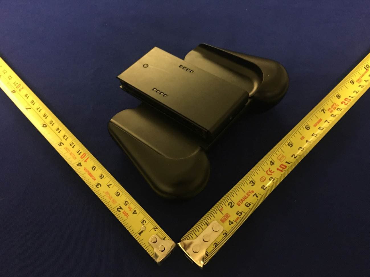
Click to zoom
Application Details
- Equipment Class
- DTS - Digital Transmission System
- Date of Grant
- Feb 11, 2020
- Application Purpose
- Original Equipment
- Date of Application
- Feb 11, 2020
- Equipment Note
- Wireless Charging Grip
- Frequency Range
- 2402.00000000 - 2480.00000000
- Company
- Powercast Corporation
- Country
- United States
Documents & Files
Document Text
Text extracted from the exhibit documents filed with the FCC. Open a document above to read the original.
Users Manual
User Manual WCG91501 – 915 MHz Wireless Charging Grip Rev 1 – 2019/11 User’s Manual – WCG91501 Grip Page 1 www.powercastco.com PRODUCT DESCRIPTION The Powercast Wireless Charging Grip (WCG91501) has been designed to charge its internal battery wirelessly while in range of a 915MHz RF Transmitter (such as the PowerSpot® TX91503 RF Wireless Power Transmitter). The Wireless Charging Grip uses this stored, wirelessly harvested power to recharge attached Joy-Con controllers. The WCG91501 is made out of durable plastic and designed to comfortably house Joy-Con controllers for wireless recharging and for enhanced game play. An optional USB-C connector can provide DC power to charge the WCG91501 at a more rapid rate. The WCG91501 includes a status LED to provide feedback on battery and charging status. Once Joy-Con controllers are properly mounted, the WCG91501 begins charging the controllers from its internal battery. FEATURES FCC approved Wirelessly rechargeable Comfortable feel Extends Joy-Con battery life Wide charging area PRODUCT CONTENTS The following items are included: Qty Description 1 Wireless Charging Grip 1 Quick Start instruction card APPLICATIONS Wireless Charging of Joy-Cons Gaming Controller Powercast®, Lifetime Power®, Powerharvester®, and Powercaster® are registered trademarks of Powercast Corporation. All other trademarks are the property of their respective owners. Powercast products and technology are covered by one or more of the following patents and other patents pending: 6,289,237 | 6,615,074 | 6,856,291 | 7,027,311 | 7,057,514 | 7,639,994 | 7,643,312 | 7,812,771 | 7,844,306 | 7,868,482 | 7,898,105 7,925,308 | 8,159,090 | 8,350,255 | 8,432,062 | 8,461,817 | 8,621,245 | 9,000,616 | 9,021,277 | 9,107,579 | 9,251,699 | 9,706,924 User Manual WCG91501 – 915 MHz Wireless Charging Grip Rev 1 – 2019/11 COMPONENT FEATURES Wireless Charging Grip User’s Manual – WCG91501 Grip www.powercastco.com Fig. 1: WCG91501 features on / off switch Page 2 User Manual WCG91501 – 915 MHz Wireless Charging Grip Rev 1 – 2019/11 User’s Manual – WCG91501 Grip Page 3 www.powercastco.com SET-UP AND OPERATION 1. Mount or place the RF transmitter in the desired location with the Powercast logo and status LED facing the direction of where the WCG91501 will be placed. 2. Turn the WCG91501 upside-down and flip the switch to the on position. 3. Slide the Joy-Con controllers downward into the brackets. The Joy-Cons will lightly click into place once secured. 4. Place the WCG91501 within 2 ft of the transmitter with the USB-C connector facing the transmitter, as seen below in Fig. 2. Fig.2: WCG91501 recharging orientation 5. Charging performance and status is communicated by the LED indicator on the WCG91501. See the table below for details. The status LED indicates the following operating conditions: LED Status Description Off Not Charging or Off WCG91501 is not charging, is powered off via the rear switch, or the internal battery is extremely discharged Single blink Green Preferred Charging WCG91501 is charging wirelessly at a high rate Single blink Yellow Fair Charging WCG91501 is charging wirelessly at a fair rate Single blink Red Poor Charging WCG91501 is charging wirelessly at a low rate Blue Wired Charging WCG91501 is charging via the USB-C port Double blink Green Fully Charged WCG91501 internal battery is fully charged Double blink Red Low Battery WCG91501 internal battery is low and recharging is needed Blue with Double blink Green Fully Charged WCG91501 is fully charged with USB-C connected Blue with Double blink Red Low Battery WCG91501 internal battery is low and charging via USB-C port 6. Use the WCG91501 to house the Joy-Con controllers during game play. 7. When done playing, return the WCG91501 to the front of the transmitter for recharging. User Manual WCG91501 – 915 MHz Wireless Charging Grip Rev 1 – 2019/11 User’s Manual – WCG91501 Grip Page 4 www.powercastco.com Notes: 1. If the WCG91501 LED does not respond when placed in front of the transmitter, verify that the switch on the back of the device is turned on. If the LED still does not respond turn the switch off for 5 seconds and then turn it back on. If the LED still does not respond the battery could be fully depleted. Place the WCG91501 in front of the PowerSpot TX91503 RF Wireless Power Transmitter and enable the transmitter manually by pressing the button on top. See the PowerSpot TX91503 instruction manual for more information. 2. When the WCG91501 will not be used for a long period of time, turn the rear switch off to avoid discharging or potentially damaging the internal battery. 3. If a firmware upgrade is available for your WCG91501, turn the switch off on the back and insert a USB-C cable. Turn the switch on and within 2 minutes, utilize the recommended mobile phone application to connect to the WCG91501 and upload the firmware upgrade. Once the upgrade is complete, remove the USB-C cable and turn the switch off and then back on. 4. The WCG91501 will only charge the inserted Joy-Con controllers if the WCG91501 internal battery has adequate charge. The Joy-Con controllers will automatically begin charging from the WCG91501 once the internal battery has been recharged to the required level. Note if the internal battery is extremely discharged causing the LED to not indicate charge status, the PowerSpot TX91503 RF Wireless Power Transmitter can be manually enabled for charging by pressing the button. SPECIFICATIONS Item Description Communication Bluetooth Low Energy (BLE) Approvals United States - FCC ID: YESWCG91501 Canada – IC ID: 8985A-WCG91501 Operating Temperature 0°C to 40°C Environment Indoor use only Color Black Dimensions 6.2” × 4.6” × 1.8” (157.5 x 116.8 x 45.7 mm) SUPPORT Technical support for Powercast products can be initiated through the following methods: Website contact form: http://www.powercastco.com/contact/ Telephone: +1 412-455-5800 User Manual WCG91501 – 915 MHz Wireless Charging Grip Rev 1 – 20…
Text truncated - open the document above for the full version.
External Photos
EUT View 1 EUT View 2 EUT I/O View
ID Label/Location Info
WCG91501 – Label Location Label Location
Internal Photos
EUT Enclosure Off View EUT Main Board Top View BT Antenna BT CHIP EUT Main Board Bottom View EUT Battery View
RF Exposure Info
Report No.: FCC_RF Exposure_SL19102101-PCC-01 Page No. 1 / 6 Report Format Version: 6.1.1 RF Exposure Report Report No.: FCC_RF Exposure_SL19102101-PCC-01 FCC ID: YESWCG91501 Test Model: WCG91501 Series Model: N/A Received Date: 01/30/2020 Test Date: 01/31/2020/-02/02/2020 Issued Date: 02/07/2020 Applicant: Powercast Corporation Address: 620 Alpha Dr, Pittsburgh, PA 15238 Issued By: Bureau Veritas Consumer Products Services, Inc. Lab Address: 775 Montague Expressway, Milpitas, CA 95035 Test Location (1): 775 Montague Expressway, Milpitas, CA 95035 FCC Registration / Designation Number: 540430 This report is for your exclusive use. Any copying or replication of this report to or for any other person or entity, or use of our name or trademark, is permitted only with our prior written permission. This report sets forth our findings solely with respect to the test samples identified herein. The results set forth in this report are not indicative or representative of the quality or characteristics of the lot from which a test sample was taken or any similar or identical product unless specifically and expressly noted. Our report includes all of the tests requested by you and the results thereof based upon the information that you provided to us. You have 60 days from date of issuance of this report to notify us of any material error or omission caused by our negligence, provided, however, that such notice shall be in writing and shall specifically address the issue you wish to raise. A failure to raise such issue within the prescribed time shall constitute your unqualified acceptance of the completeness of this report, the tests conducted and the correctness of the report contents. Unless specific mention, the uncertainty of measurement has been explicitly taken into account to declare the compliance or non-compliance to the specification. The report must not be used by the client to claim product certification, approval, or endorsement by A2LA or any government agencies. Report No.: FCC_RF Exposure_SL19102101-PCC-01 Page No. 2 / 6 Report Format Version: 6.1.1 Table of Contents Release Control Record .................................................................................................................................. 3 1 Certificate of Conformity ...................................................................................................................... 4 2 Evaluation Result .................................................................................................................................. 5 3 SAR Test Exclusion Thresholds .......................................................................................................... 6 4 Conclusion ............................................................................................................................................ 6 Report No.: FCC_RF Exposure_SL19102101-PCC-01 Page No. 3 / 6 Report Format Version: 6.1.1 Release Control Record Issue No. Description Date Issued FCC_RF Exposure_SL19102101-PCC-01 Orignal Release 02/07/2020 Report No.: FCC_RF Exposure_SL19102101-PCC-01 Page No. 4 / 6 Report Format Version: 6.1.1 1 Certificate of Conformity Product: Wireless Charging Grips Brand: Powercast Test Model: WCG91501 Series Model: N/A Sample Status: Engineering sample Applicant: Powercast Corporation Test Date: 01/31/2020/-02/02/2020 Standards: FCC Part 2 (Section 2.1093) KDB 447498 D01 General RF Exposure Guidance v06 IEEE C95.1-1992 The above equipment has been tested by Bureau Veritas Consumer Products Services, Inc., Milpitas Branch, and found compliance with the requirement of the above standards. The test record, data evaluation & Equipment Under Test (EUT) configurations represented herein are true and accurate accounts of the measurements of the sample’s EMC characteristics under the conditions specified in this report. Prepared by : , Date: 02/06/2020 Gary Chou / Compliance Engineer Approved by : , Date: 02/07/2020 Chen Ge / Engineer Reviewer Report No.: FCC_RF Exposure_SL19102101-PCC-01 Page No. 5 / 6 Report Format Version: 6.1.1 2 Evaluation Result Following FCC KDB 447498 D01 “General SAR test exclusion guidance” The corresponding SAR Exclusion Threshold condition, listed below: 1) The 1-g and 10-g SAR test exclusion thresholds for 100 MHz to 6 GHz at test separation distances ≤ 50 mm are determined by: [(max. power of channel, including tune-up tolerance, mW)/(min. test separation distance, mm)] ·[√f(GHz)] ≤ 3.0 for 1-g SAR and ≤ 7.5 for 10-g extremity SAR, where f(GHz) is the RF channel transmit frequency in GHz. Power and distance are rounded to the nearest mW and mm before calculation. The result is rounded to one decimal place for comparison The test exclusions are applicable only when the minimum test separation distance is ≤ 50 mm and for transmission frequencies between 100 MHz and 6 GHz. When the minimum test separation distance is < 5 mm, a distance of 5 mm is applied to determine SAR test exclusion. 2) At 100 MHz to 6 GHz and for test separation distances > 50 mm, the SAR test exclusion threshold is determined according to the following: a) [Threshold at 50 mm in step 1) + (test separation distance - 50mm)·( f(MHz)/150)] mW, at 100MHz to 1500 MHz b) [Threshold at 50 mm in step 1) + (test separation distance - 50 mm)·10] mW at > 1500 MHz and ≤ 6 GHz 3) At frequencies below 100 MHz, the following may be considered for SAR test exclusion. a) The threshold at the corresponding test separation distance at 100 MHz in step 2) is multiplied by [1 + log(100/f(MHz))] for test separation distances > 50 mm and < 200 mm. b) The threshold determined by the equation in a) for 50 mm and 100 MHz is multiplied by ½ for test separation distances ≤ 50 mm. c) SAR measurement procedures are not established below 100 MHz. When SAR test exclusion cannot be applied, a KDB inquiry is required to determine SAR evaluation requirements for any test results to be acceptable. Report No.: FCC_RF Exposu…
Text truncated - open the document above for the full version.
Test Report
Report No.: FCC_IC_RF_SL19102101-PCC-01 Page No. 1 / 38 Report Format Version: 6.1.1 FCC IC Test Report (BT-LE) Report No.: FCC_IC_RF_SL19102101-PCC-01 FCC ID: YESWCG91501 IC: 8985A-WCG91501 Test Model: WCG91501 Received Date: 01/30/2020 Test Date: 01/31/2020/-02/02/2020 Issued Date: 02/07/2020 Applicant: Powercast Corporation Address: 620 Alpha Dr, Pittsburgh, PA 15238 Manufacturer: Powercast Corporation Address: 620 Alpha Dr, Pittsburgh, PA 15238 Issued By: Bureau Veritas Consumer Products Services, Inc. Lab Address: 775 Montague Expressway, Milpitas, CA 95035 Test Location (1): 775 Montague Expressway, Milpitas, CA 95035 FCC Registration / Designation Number: 540430 ISED# / CAB identifier: 4842D This report is for your exclusive use. Any copying or replication of this report to or for any other person or entity, or use of our name or trademark, is permitted only with our prior written permission. This report sets forth our findings solely with respect to the test samples identified herein. The results set forth in this report are not indicative or representative of the quality or characteristics of the lot from which a test sample was taken or any similar or identical product unless specifically and expressly noted. Our report includes all of the tests requested by you and the results thereof based upon the information that you provided to us. You have 60 days from date of issuance of this report to notify us of any material error or omission caused by our negligence, provided, however, that such notice shall be in writing and shall specifically address the issue you wish to raise. A failure to raise such issue within the prescribed time shall constitute your unqualified acceptance of the completeness of this report, the tests conducted and the correctness of the report contents. Unless specific mention, the uncertainty of measurement has been explicitly taken into account to declare the compliance or non-compliance to the specification. The report must not be used by the client to claim product certification, approval, or endorsement by A2LA or any government agencies. Report No.: FCC_IC_RF_SL19102101-PCC-01 Page No. 2 / 38 Report Format Version: 6.1.1 Table of Contents Release Control Record .................................................................................................................................. 4 1 Certificate of Conformity ...................................................................................................................... 5 2 Summary of Test Results ..................................................................................................................... 6 2.1 Measurement Uncertainty ................................................................................................................... 6 2.2 Modification Record ............................................................................................................................ 6 3 General Information .............................................................................................................................. 7 3.1 General Description of EUT ................................................................................................................ 7 3.2 Description of Test Modes ................................................................................................................... 8 3.2.1 Test Mode Applicability and Tested Channel Detail ............................................................................. 9 3.3 Description of Support Units ............................................................................................................. 10 3.3.1 Configuration of System under Test .................................................................................................. 10 3.4 General Description of Applied Standards ........................................................................................ 10 4 Test Types and Results ....................................................................................................................... 11 4.1 Radiated Emission and Bandedge Measurement .............................................................................. 11 4.1.1 Limits of Radiated Emission and Bandedge Measurement ............................................................... 11 4.1.2 Test Instruments ................................................................................................................................ 12 4.1.3 Test Procedures ................................................................................................................................. 13 4.1.4 Deviation from Test Standard ............................................................................................................ 14 4.1.5 Test Setup .......................................................................................................................................... 14 4.1.6 EUT Operating Conditions ................................................................................................................. 15 4.1.7 Test Results ....................................................................................................................................... 16 4.2 Conducted Emission Measurement .................................................................................................. 22 4.2.1 Limits of Conducted Emission Measurement .................................................................................... 22 4.2.2 Test Instruments ................................................................................................................................ 22 4.2.3 Test Procedures ................................................................................................................................. 23 4.2.4 Deviation from Test Standard ..........................................................................................…
Text truncated - open the document above for the full version.
Test Setup Photos
Conducted Emission Front View Conducted Emission Rear View Radiated Emission Test below 1GHz Front View Radiated Emission Test below 1GHz Rear View Radiated Emission Test above 1GHz Front View Radiated Emission Test above 1GHz Rear View
Contact Information
Applicant
Charles Greene(CTO)
Test Firm
Bureau Veritas Consumer Products Services, Inc.Sarb Shelopal
[email protected]+1 925 963 4420
Technical Specifications
| # | Rule Parts | Frequency Range | Power Output |
|---|---|---|---|
| 1 | 15C | 2.40 GHz - 2.48 GHz | 500.00 µW |
Other Applications from Powercast Corporation
YESPCR91502-M
Apr 23, 2023PCR91502-M Rain RFID Module
Equipment Class
DSS - Part 15 Spread Spectrum Transmitter
YESPCR91501
Dec 29, 2022PCR91501 RFID Reader
Equipment Class
DSS - Part 15 Spread Spectrum Transmitter
YESTX91501
Sep 29, 2010RF Powering Device
Equipment Class
DTS - Digital Transmission System