YETCELFI-RS225CUAAT&T Provider Specific Consumer Signal Booster
Nextivity Incorporated
Click to zoom
Application Details
- Equipment Class
- B2P - Part 20 Provider-Specific Consumer Booster (CMRS)
- Date of Grant
- Apr 01, 2014
- Application Purpose
- Original Equipment
- Date of Application
- Mar 02, 2014
- Equipment Note
- AT&T Provider Specific Consumer Signal Booster
- Frequency Range
- 1930.00000000 - 1995.00000000
- Company
- Nextivity Incorporated
- Country
- United States
Documents & Files
Document Text
Text extracted from the exhibit documents filed with the FCC. Open a document above to read the original.
Users Manual
Step 1 Find the spot with the best 3G coverage: The first step in setting up your Cel-Fi system is to find the spot in your home or office that has the best 3G coverage by using your phone (3G icon must be displayed). This is typically by a window, and if you are in a multi-story building, upstairs windows are usually better than downstairs windows. Step 2 Plug in the Window Unit: Take the Window Unit and one power supply out of the box (both power supplies are identical, so you can use either one). Plug the Window Unit into an easily accessible outlet. Check to make sure that you can see at least 1 “Bar” on the display in the center of the device. If you do not see at least 1 bar, try a different location. CEL - FIRS 2duaL Band Quick Start Guide 3G WINDOW UNIT WIndOW unIT COVERaGE unIT Congratulations on your new indoor signal solution. This Cel-Fi system is designed to provide you with significant improvements in coverage as well as 3G data rates. Setting up the system is extremely simple and consists of placing and plugging in two components; a Window unit and a Coverage unit. By spending just a few minutes using the instructions in this guide, you can optimize the installation and get the very most from your new Cel-Fi System. If you have any trouble during setup, please use the trouble shooting steps included in this guide. In the package you will find: • Window unit • Coverage unit • Two Power adapters This is a COnSumER device. BEFORE uSE, you muST REGISTER ThIS dEVICE with your wireless provider and have your provider’s consent. most wireless providers consent to the use of signal boosters. Some providers may not consent to the use of this device on their network. If you are unsure, contact your provider. You muST operate this device with approved antennas and cables as specified by the manufacturer. antennas muST be installed at least 20 cm (8 inches) from any person. You muST cease operating this device immediately if requested by the FCC or a licensed wireless service provider. WaRnInG. E911 location information may not be provided or may be inaccurate for calls served by using this device. When used with any mobile device utilizing the 1710-1755 mhz band, the FCC limits booster equipment placement to a maximum of 10 meters above ground level. Installation of this equipment which does not comply with federal requirements may subject the owner to FCC enforcement action. nOT FOR RESaLE. Changes or modifications not expressly approved by nextivity, Inc. could void the user’s authority to operate the equipment. nOTE: This equipment has been tested and found to comply with the limits for a Class B digital device, pursuant to part 15 of the FCC Rules. These limits are designed to provide reasonable protection against harmful interference in a residential installation. This equipment generates, uses and can radiate radio frequency energy and, if not installed and used in accordance with the instructions, may cause harmful interference to radio communications. however, there is no guarantee that interference will not occur in a particular installation. If this equipment does cause harmful interference to radio or television reception, which can be determined by turning the equipment off and on, the user is encouraged to try to correct the interference by one or more of the following measures: • Reorient or relocate the receiving antenna. • Increase the separation between the equipment and receiver. • Connect the equipment into an outlet on a circuit different from that to which the receiver is connected. • Consult the dealer or an experienced radio/TV technician for help Cel-Fi is a registered trademark of nextivity, Inc. Need Help? Visit us at www.celfihelp.com for an installation video and other helpful information regarding installation and trouble shooting. Step 4 Place the Coverage Unit: move to a location in your home where you need to have improved coverage. Plug the Coverage Unit into an easily accessible outlet. Wait until the numeric display stops cycling. This could take several minutes. at this point you should see a green icon indicating that the unit is working properly. It is possible to place the Coverage Unit so far away that it cannot communicate with the Window Unit. If this happens, a red icon will illuminate indicating that you need to move the Coverage Unit closer to the Window Unit. TOO CLOSE a zero on the numeric display indicates that the Coverage Unit needs to be moved farther away from the Window Unit. GOOD This green icon indicates that the Coverage Unit is functioning normally. TOO FAR This red icon indicates that the Coverage Unit needs to be moved closer to the Window Unit. Step 3 Optimize the Window Unit Placement: The number of bars you can see on the Window Unit make a significant difference in the operation of the Cel-Fi system. Try moving the Window Unit to a couple of different spots to see if you can get a better signal; the more bars the better. Step 5 Optimize The Coverage Unit Placement: The farther away you place the Coverage Unit from the Window Unit the better the coverage in your home, so put the Coverage Unit as far away from the Window Unit as possible. The number shown on the side of the display gives you an indication as to the quality of the placement. Test two or three locations and for best results; try and get an 8 or 9 on the display. COVERAGE UNIT WIndOW unIT COVERaGE unIT WINDOW UNIT CEL - FIRS 2 Trouble Shooting Indicator Issue Try This Indicator Issue Try This Indicator Issue Try This Improving Performance Issue Try This no lights on Window Unit display. Status indicator is flashing green for more than a minute. Status indicator is on solid red. no segment lit on signal display and status indicator on solid green. Center three bars on signal display are flashing. no lights on Coverage Unit display. 7 segment display is cycling for more than a minute. 7 segment display shows a value of 0. Red “Too Far” Indicator. Red Status Indi…
Text truncated - open the document above for the full version.
RF Exposure Info
Page 1 of 4 Report No: 95295-23 RADIO FREQUENCY EXPOSURE REPORT FOR THE Device: Provider Specific Consumer Signal Booster Model: CELFI-RS225CU Report No.: 95295-23 Date of issue: March 26, 2014 PREPARED FOR: Nextivity, Inc. 12230 World Trade Dr. San Diego CA 92128 PREPARED BY: Eddie Wong CKC Laboratories, Inc. 5046 Sierra Pines Drive Mariposa, CA 95338 The test data contained in this report documents the observed testing parameters pertaining to and are relevant for only the sample equipment tested in the agreed upon operational mode(s) and configuration(s) as identified herein. Compliance assessment remains the client’s responsibility. This report may not be used to claim product endorsement by A2LA or any government agencies. This test report has been authorized for release under quality control from CKC Laboratories, Inc. Steve Behm Director of Quality Assurance & Engineering Services CKC Laboratories, Inc. Page 2 of 4 Report No: 95295-23 Purpose: To demonstrate compliance with United States RF Exposure requirements for Portable equipment (devices used ≤20cm from the body) or Mobile equipment (devices used >20cm from the body) with power output below exemption levels and Mobile equipment, where Maximum Permissible Exposure (MPE) Calculations apply. United States Compliance Requirements (1.1310): RF Exposure Evaluation Limits Occupational / Controlled Exposure Frequency Range (MHz) Electric Field Strength (V/m) Magnetic Field Strength (A/m) Power Density (mW/cm 2 ) Averaging Time (minutes) 0.3-3.0 614 1.63 *(100) 6 3.0-30 1842/f 4.89/f *(900/f 2 ) 6 30-300 61.4 0.163 1 6 300-1500 --- --- f/300 6 1500-100,000 --- --- 5.0 6 RF Exposure Evaluation Limits General Population / Uncontrolled Exposure Frequency Range (MHz) Electric Field Strength (V/m) Magnetic Field Strength (A/m) Power Density (mW/cm 2 ) Averaging Time (minutes) 0.3-1.34 614 1.63 *(100) 30 1.34-30 824/f 2.19/f *(180/f 2 ) 30 30-300 27.5 0.073 0.2 30 300-1500 --- --- f/1500 30 1500-100,000 --- --- 1.0 30 * Plane wave equivalent power density Limit is calculated based on the mid-band frequency used in the operating frequency range. Exemption Level: Power output <60/f GHz (mW) 60/ 0.881Gz = 68.1mW 60/ 1.960 = 30.6mW. 60/5.598=10.7mW Page 3 of 4 Report No: 95295-23 Device and Antenna Operating Configuration: Device operating at maximum output power with continuous transmission of modulated data. Test Procedure: This equipment is evaluated in accordance with the guidelines set forth in OET Guide 65 & ANSI C95.1 for the US. Other Considerations: None MPE Calculations Applicability: Limit Used X General Population / Uncontrolled Exposure Occupational / Controlled Exposure RF Exposure Exemption No United States Equipment Operational Details: Config# Freq Range Meas Power (dBm) Antenna Gain (dBi) Antenna Type EIRP (dBm) EIRP (mW) US mW/cm 2 1 1930-1955 7.20 2.00 Integral 9.20E+00 8.31763771 1.00 2 869-894 6.70 -3.00 Integral 3.70E+00 2.34422882 0.59 3 5470-5725 20.60 5.50 Integral 2.61E+01 407.380278 1.00 Measurements based from EMC Test Report(s): 95295-10 Config Freq Range EIRP Distance US # (mW) (cm) mW/cm 2 Limit 1 1930-1955 8.31763771 20.00 0.001655 1.00 2 869-894 2.34422882 20.00 0.000466 0.59 3 5470-5725 407.380278 20.00 0.08 1.00 Exemption Level: Power output <60/f GHz (mW) 60/ 0.881Gz = 68.1mW, 60/ 1.960GHz = 30.6mW. 60/5.598GHz=10.7mW EXEMPTION MPE Calculation: 2 4d EIRP DensityPower Given: EIRP in mW or W and d in cm or m\ Page 4 of 4 Report No: 95295-23 Summary: Exemptions: 1930-1955MHz, 869-894MHz In the case the equipment meets compliance requirements by exemption the product is approved for use under mobile or portable conditions without further testing under the condition that any additional collocation or simultaneous transmission requirements (including necessary separation distances) have been met. MPE Calculation Results: 5470-5725MHz In the case the equipment meets compliance by MPE Calculations the product is approved for use under mobile conditions without further testing under the condition that any additional collocation or simultaneous transmission requirements (including necessary separation distances) have been met. It is assumed that the manufacturer shall design the equipment such that the minimum separation distance of 20cm (or greater, as listed above) is met or that the manufacturer provides a protection guide (or installation instructions) to the end user such that the antenna(s) may be installed in accordance with the manufacturer’s instructions in such a manor to maintain the minimum separation distance. The Absorption and distribution of Electromagnetic energy in the body is a very complex phenomena that depends on the mass, shape and physiological condition of the body; the orientation of the body with respect to the fields; and, the electrical properties of the body and the environment. Variables that may play a substantial role in possible biological effects are those that characterize the environment (including but not limited to: ambient temperature, air velocity, relative humidity and body insulation); and those that characterize the individual (including but not limited to: age, gender, activity level and existing debilitation or disease). Because innumerable factors may interact to determine specific biological effects of exposure to electromagnetic fields, any protection guide should consider both intended and unintended operational environments and provide guidance for installation and use of the product such that proper separation distances can be maintained. (ANSI C95.1) References Federal Communications Commission Knowledge Database (KDB) Publication 447498, “What are the RF exposure requirements and procedures for mobile and portable devices?” As in effect on the issue date of this report. Federal Communications Commission Bulletin OET 65 Supplement C, “Evaluating Compliance with FCC Guidelines for Human Exposure to Radiofrequency Electromagnetic Fields” June 2001 Title 47 Code o…
Text truncated - open the document above for the full version.
Test Report
This report contains a total of 82 pages and may be reproduced in full only. Partial reproduction may only be done with the written consent of CKC Laboratories, Inc. Nextivity, Inc. TEST REPORT FOR Provider Specific Consumer Signal Booster, CELFI-RS225CU and Provider Specific Consumer Signal Booster, CELFI-RS225WU Tested To The Following Standards: FCC Part 20.21 Report No.: 95295-10 Date of issue: February 12, 2014 We strive to create long-term, trust based relationships by providing sound, adaptive, customer first testing services. We embrace each of our customers’ unique EMC challenges, not as an interruption to set processes, but rather as the reason we are in business. Page 2 of 82 Report No.: 95295-10 TABLE OF CONTENTS Administrative Information .......................................................................................................................... 3 Test Report Information ............................................................................................................................................ 3 Report Authorization ................................................................................................................................................. 3 Test Facility Information ............................................................................................................................................ 4 Software Versions ...................................................................................................................................................... 4 Site Registration & Accreditation Information .......................................................................................................... 4 Summary of Results ................................................................................................................................................... 5 Conditions During Testing ......................................................................................................................................... 5 Equipment Under Test ............................................................................................................................................... 6 Peripheral Devices ..................................................................................................................................................... 6 FCC Part 20.21 ............................................................................................................................................... 7 7.1 Authorized Frequency Band Verification and CMRS Provider ............................................................................. 7 7.1 Summary of Results ......................................................................................................................................... 7 7.2 Maximum Power Measurement ........................................................................................................................ 19 7.2 Summary of Results ....................................................................................................................................... 20 7.3 Maximum Booster Gain Computation ............................................................................................................... 24 7.3 Summary of Results ....................................................................................................................................... 25 7.4 Intermodulation Product ................................................................................................................................... 26 7.4 Summary of Results ....................................................................................................................................... 27 7.5 Out of Band Emissions ....................................................................................................................................... 33 7.5 Summary of Results ....................................................................................................................................... 34 7.7 Noise Limits........................................................................................................................................................ 44 7.7 Summary of Results ....................................................................................................................................... 47 7.8 Uplink Inactivity ................................................................................................................................................. 56 7.8 Summary of Results ....................................................................................................................................... 57 7.9 Variable Booster Gain ........................................................................................................................................ 59 7.9 Summary of Results ....................................................................................................................................... 62 7.11 Anti-oscillation ................................................................................................................................................. 67 7.11 Summary of Results ..................................................................................................................................... 68 7.13 Spectrum Block Filtering .................................................................................................................................. 75 7.14 Out of Band Gain Limits ................................................................................................................................... 76 7.14 Summary of Results ..................................................................................................................................... 77 Page 3 of 82 Report No.: 95295-10 ADMINISTRATI…
Text truncated - open the document above for the full version.
Test Report
Page 51 of 82 Report No.: 95295-10 7.7(n) - (t), DL_869-894MHz_Test CF-3MHz 7.7(n) - (t),DL_1930-1990MHz_Test CF+3MHz Page 52 of 82 Report No.: 95295-10 7.7(n) - (t),DL_1930-1990MHz_Test CF-3MHz 7.7(n) - (t),UL_824-849MHz_Test CF+3MHz Page 53 of 82 Report No.: 95295-10 7.7(n) - (t),UL_824-849MHz_Test CF-3MHz 7.7(n) - (t),UL_1850-1910MHz_Test CF+3MHz Page 54 of 82 Report No.: 95295-10 7.7(n) - (t),UL_1850-1910MHz_Test CF-3MHz Test Setup Photo(s) Test Setup, Noise Limit 1 Note: The sign in the photo has the incorrect numbering reference. The proper reference is 7.7. Page 55 of 82 Report No.: 95295-10 Test Setup, Noise Limit 2 Note: The sign in the photo has the incorrect numbering reference. The proper reference is 7.7. Page 56 of 82 Report No.: 95295-10 7.8 Uplink Inactivity Test Conditions / Setup Test Location: CKC Laboratories • 110 Olinda Place • Brea, CA 92823 • 714-993-6112 Customer: Nextivity, Inc. Specification: 7.8 Uplink Inactivity Work Order #: 95295 Date: 1/8/2014 Test Type: Conducted Emissions Equipment: Provider Specific Consumer Signal Booster Sequence#: 1 Manufacturer: Nextivity, Inc. Tested By: E. Wong Model: CELFI-RS225CU, CELFI-RS225WU, 110V 60Hz S/N: 157216000246, 157216000246 Test Equipment: ID Asset # Description Model Calibration Date Cal Due Date AN02869 Spectrum Analyzer E4440A 2/6/2013 2/6/2015 AN02946 Cable 32022-2-2909K- 36TC 7/31/2013 7/31/2015 AN03430 Attenuator 75A-10-12 9/5/2013 9/5/2015 Equipment Under Test (* = EUT): Function Manufacturer Model # S/N Provider Specific Consumer Signal Booster* Nextivity, Inc. CELFI-RS225CU 157216000246 Provider Specific Consumer Signal Booster Nextivity, Inc. CELFI-RS225WU 157216000246 Support Devices: Function Manufacturer Model # S/N Power Supply Nextivity WRG15F-120AB 20120111 Power Supply Nextivity WRG15F-120AB 20120815 Signal Generator Agilent E4438C MY42082260 Test Conditions / Notes: The EUT is provider specific signal booster pair consisted of a Window unit (WU) and a Coverage unit (CU) using proprietary 5.8 GHz Wireless interface. For testing purposes, the EUT are placed on the test bench, connected via coax cable and 50 dB attenuators. Tx of WU is connected to RX of CU, RX of WU is connected to UNII TX port of CU. Intended band of operation UL= 824-849 MHz, 1850-1910 MHz, DL= 869-894 MHz 1930-1990 MHz, Delta Marker 2R- marker 2 is the measured Uplink inactivity time. Test environment conditions: 23°C, 15% Relative Humidity, 100kPa Page 57 of 82 Report No.: 95295-10 7.8 Summary of Results Pass: As demonstrated in the test data section, the time between Cursor R2 where the uplink signal was turned off and cursor #2 where the noise level returned to the TX off level is less than 5 second. Test Data 824-849MHz Page 58 of 82 Report No.: 95295-10 1850-1915MHz Test Setup Photo(s) Note: The sign in the photo has the incorrect numbering reference. The proper reference is 7.8. Page 59 of 82 Report No.: 95295-10 7.9 Variable Booster Gain Test Conditions / Setup Test Location: CKC Laboratories • 110 Olinda Place • Brea, CA 92823 • 714-993-6112 Customer: Nextivity, Inc. Specification: 7.9 Variable Booster Gain Work Order #: 95295 Date: 1/10,16/2014 Test Type: Conducted Emissions Equipment: Provider Specific Consumer Signal Booster Sequence#: 1 Manufacturer: Nextivity, Inc. Tested By: E. Wong Model: CELFI-RS225CU, CELFI-RS225WU, 110V 60Hz S/N: 157216000246, 157216000246 Test Equipment: ID Asset # Description Model Calibration Date Cal Due Date AN02869 Spectrum Analyzer E4440A 2/6/2013 2/6/2015 AN02946 Cable 32022-2-2909K- 36TC 7/31/2013 7/31/2015 AN03430 Attenuator 75A-10-12 9/5/2013 9/5/2015 Equipment Under Test (* = EUT): Function Manufacturer Model # S/N Provider Specific Consumer Signal Booster* Nextivity, Inc. CELFI-RS225CU 157216000246 Provider Specific Consumer Signal Booster Nextivity, Inc. CELFI-RS225WU 157216000246 Support Devices: Function Manufacturer Model # S/N Power Supply Nextivity WRG15F-120AB 20120111 Power Supply Nextivity WRG15F-120AB 20120815 Signal Generator Agilent E4438C MY42082260 Base Station Simulator Agilent 8960 GB47320116 Page 60 of 82 Report No.: 95295-10 Test Conditions / Notes: The EUT is provider specific signal booster pair consisted of a Window unit (WU) and a Coverage unit (CU) using proprietary 5.8 GHz Wireless interface. For testing purposes, the EUT are placed on the test bench, connected via coax cable and 50 dB attenuators. Tx of WU is connected to RX of CU, RX of WU is connected to UNII TX port of CU. Intended band of operation UL= 824-849 MHz, 1850-1910 MHz, DL= 869-894 MHz 1930-1990 MHz, MSCL of 38.2 dB ( 1850-1910, 1930-1990MHz) and 41.4 ( 824-869MHz, , 869-894MHz) calculation provided in FCC submittal package. The test was performed with the booster operating in Test mode bypassing the RF input limit function. In operation, the UL path cease transmit operation at RSSI exceeding -40dBm. The system gain presented in the UL plot, at BSCL of RSSI equivalent of -40dBm ( BSCL of 80dB) , the system is designed to enter transmit off and the plot represents system gain of Transmit power off. Variable gain UL timing plot: time between market 1 and 1R is the reaction time when the BSCL dropped 20dB. Test environment conditions: 23°C, 15% Relative Humidity, 100kPa 0.0 10.0 20.0 30.0 40.0 50.0 60.0 70.0 80.0 90.0 100.0 60.070.080.090.0100.0110.0120.0130.0 UL Gain (dB) MSCL= 31.4 dB BSCL (dB) Booster UL Gain Limit Limit UL Gain 824-849MHzData UL Gain 824-849MHz Page 61 of 82 Report No.: 95295-10 0.0 10.0 20.0 30.0 40.0 50.0 60.0 70.0 80.0 90.0 100.0 60.070.080.090.0100.0110.0120.0130.0 UL Gain (dB) MSCL= 38.2 dB BSCL (dB) Booster UL Gain Limit Limit UL Gain 1850-1910MHzData UL Gain 1850-1910MHz 0.0 10.0 20.0 30.0 40.0 50.0 60.0 70.0 80.0 90.0 100.0 60.070.080.090.0100.0110.0120.0130.0 Gain (dB) MSCL = 31.4 db BSCL (dB) Booster DL Gain Limit 869-894MHz Dl Gain limitData 869-894MHz_DL_Gain Page 62 of 82 Report No.: 95295-10 7.9 Summary of Results Pass: As demonstrated in the test data section, th…
Text truncated - open the document above for the full version.
Test Report
Radio Test Report FCC Part 22 and RSS 132 869 MHz to 894 MHz Model: CELFI-RS225CU IC CERTIFICATION #: 9298A-CRS225CU FCC ID: YETCELFI-RS225CU APPLICANT: Nextivity Inc. 12230 World Trade Drive Suite 250 San Diego, CA 92128 TEST SITE(S): Elliott Laboratories 41039 Boyce Road. Fremont, CA. 94538-2435 IC SITE REGISTRATION #: 2845B-3; 2845B-4, 2845B-5, 2845B-7 REPORT DATE: May 9, 2012 FINAL TEST DATES: March 22, 23, 26, 27, 29 and April 11, 2012 TOTAL NUMBER OF PAGES: 48 PROGRAM MGR / QUALITY ASSURANCE DELEGATE / TECHNICAL REVIEWER: FINAL REPORT PREPARER: ______________________________ ______________________________ David W. Bare David Guidotti Chief Engineer Senior Technical Writer Elliott Laboratories is accredited by the A2LA, certificate number 0214.26, to perform the test(s) listed in this report, except where noted otherwise. This report and the information contained herein represent the results of testing test articles identified and selected by the client performed to specifications and/or procedures selected by the client. National Technical Systems (NTS) makes no representations, expressed or implied, that such testing is adequate (or inadequate) to demonstrate efficiency, performance, reliability, or any other characteristic of the articles being tested, or similar products. This report should not be relied upon as an endorsement or certification by NTS of the equipment tested, nor does it represent any statement whatsoever as to its merchantability or fitness of the test article, or similar products, for a particular purpose. This report shall not be reproduced except in full File: R87350 Page 1 Elliott Laboratories -- EMC Department Test Report Report Date: May 9, 2012 File: R87350 Page 2 REVISION HISTORY Rev# Date Comments Modified By - 05-09-2012 First release Elliott Laboratories -- EMC Department Test Report Report Date: May 9, 2012 File: R87350 Page 3 TABLE OF CONTENTS REVISION HISTORY ................................................................................................................................................ 2 TABLE OF CONTENTS ............................................................................................................................................ 3 SCOPE .......................................................................................................................................................................... 4 OBJECTIVE ................................................................................................................................................................ 5 STATEMENT OF COMPLIANCE ........................................................................................................................... 5 DEVIATIONS FROM THE STANDARDS .............................................................................................................. 5 TEST RESULTS .......................................................................................................................................................... 6 FCC PART 22 AND RSS-132 (HANDSET OR OTHER UE) ...................................................................................... 6 EXTREME CONDITIONS ...................................................................................................................................... 7 MEASUREMENT UNCERTAINTIES .................................................................................................................... 7 EQUIPMENT UNDER TEST (EUT) DETAILS ...................................................................................................... 8 GENERAL ................................................................................................................................................................ 8 ANTENNA SYSTEM .............................................................................................................................................. 8 ENCLOSURE ........................................................................................................................................................... 8 MODIFICATIONS ................................................................................................................................................... 8 SUPPORT EQUIPMENT ......................................................................................................................................... 8 EUT INTERFACE PORTS ...................................................................................................................................... 9 EUT OPERATION ................................................................................................................................................... 9 TESTING ................................................................................................................................................................... 10 GENERAL INFORMATION ................................................................................................................................. 10 RF PORT MEASUREMENT PROCEDURES ...................................................................................................... 11 OUTPUT POWER .................................................................................................................................................. 11 BANDWIDTH MEASUREMENTS ...................................................................................................................... 12 CONDUCTED SPURIOUS EMISSIONS .............................................................................................................. 12 TRANSMITTER MASK MEASUREMENTS ....................................................................................................... 13 FREQUENCY STABILITY ................................................................................................................................... 13 TRANSIENT FREQUENCY…
Text truncated - open the document above for the full version.
Contact Information
Applicant
Michiel Lotter(Vice President, Engineering)
Technical Contact
Nextivity IncorporatedMichiel Lotter
[email protected](858) 485-9422
12230 Wolrd Trade Drive · San Diego, California · United States
Non-Technical Contact
CKC Certification Services, LLCRandy Clark
[email protected]209-966-5240
Test Firm
CKC Laboratories, Inc.Steve Behm
Technical Specifications
| # | Rule Parts | Frequency Range | Power Output | Emission | Tolerance |
|---|---|---|---|---|---|
| 2 | 24E | 1.93 GHz - 2.00 GHz | 8.30 mW | F9W | 0.91 ppm |
Other Applications from Nextivity Incorporated
YETA91-JV4
Sep 12, 2024Smart Server Antenna
Equipment Class
DTS - Digital Transmission System
YETG41-CE
Jan 10, 2024Cellular Signal Booster with BLE
Equipment Class
B2I - Part 20 Industrial Booster (CMRS)
YETA71-JV4
Oct 02, 2023Smart Server Antenna
Equipment Class
DTS - Digital Transmission System
YETQ42-Z1CNU
May 05, 2023Provider-Specific Consumer Signal Booster
Equipment Class
B2P - Part 20 Provider-Specific Consumer Booster (CMRS)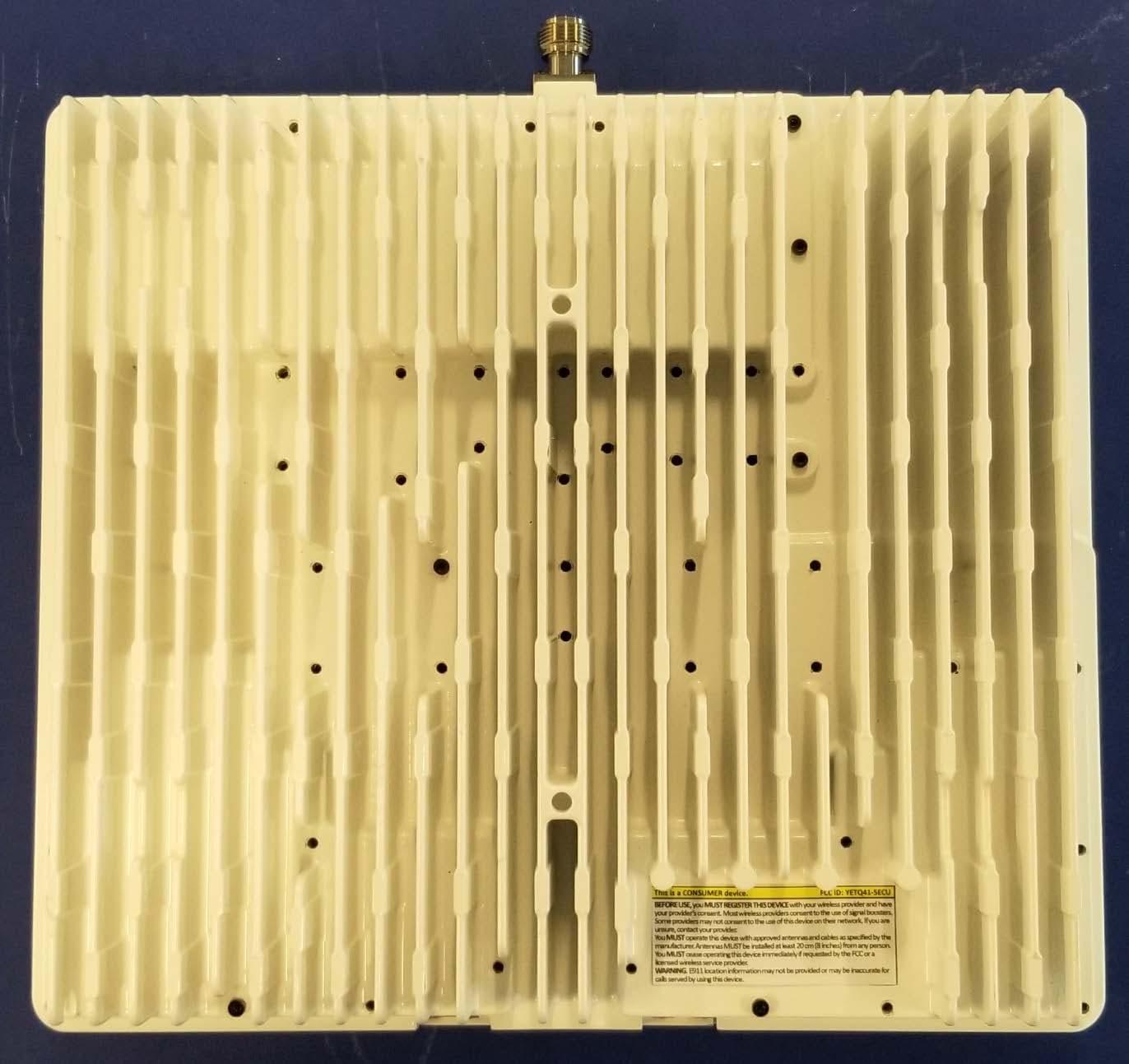
YETQ41-BXCU
May 05, 2023Provider-Specific Consumer Signal Booster
Equipment Class
B2P - Part 20 Provider-Specific Consumer Booster (CMRS)