YETCELFI-RSCU104Cel-Fi Residential System
Nextivity Incorporated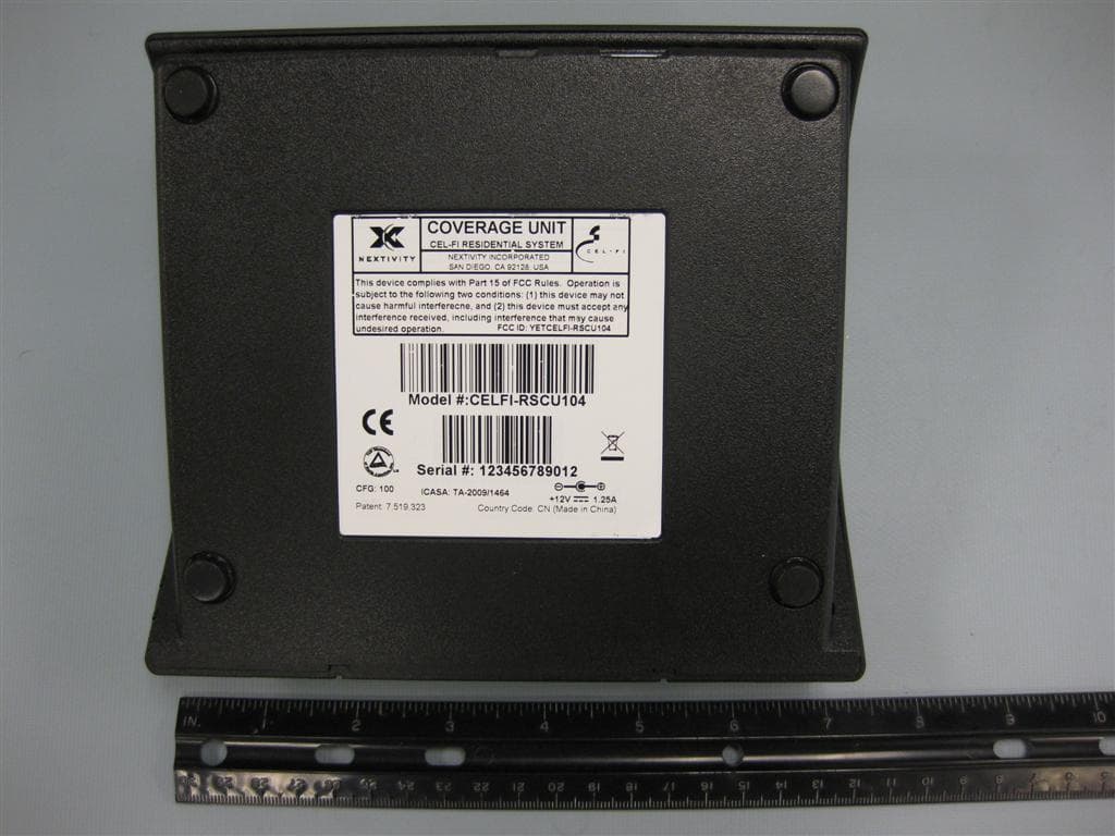
Click to zoom
Application Details
- Equipment Class
- TNB - Licensed Non-Broadcast Station Transmitter
- Date of Grant
- Sep 19, 2010
- Application Purpose
- Original Equipment
- Date of Application
- May 23, 2010
- Equipment Note
- Cel-Fi Residential System
- Frequency Range
- 2112.40000000 - 2152.60000000
- Company
- Nextivity Incorporated
- Country
- United States
Documents & Files
Document Text
Text extracted from the exhibit documents filed with the FCC. Open a document above to read the original.
Users Manual
2 Step Quick Start Guide The Cel-Fi Window Unit takes the strongest cell signal in your home and distributes it throughout via the Coverage Unit Mobile signalbefore installation Mobile signalafter installation PATENT 7,519,323 Power off(no green light)Status redStatus flashing redStatus flashing green for more than a minute 1. Is the Unit plugged in? 2. Is there power to the outlet? 3. Try exchanging power supplies with the other unit to see if the power supply is defective.1. Unplug the unit, wait a few minutes, and try again. 2. Visit the installation support section at: www.celfihelp.com for more information. 1. Do not cover the Unit or block the vents. 2. Move the Unit to a cooler spot. 3. The unit will start operating again when it cools. 1. Wait longer. System is verifying regulatory compliance. This could take up to 30 minutes.2. Make sure Units are not next to a Wi-Fi router. Indicator Problem Try this: Trouble Shooting Guide ((( ))) ((( ))) If there is a system fault, the Coverage Unit will display an error message on the display in the location where the coverage number is usually displayed (see below).If this occurs the message will alternate between displaying an “E” (for error) and then a number. The table below shows what values will be displayed and what they mean.“E1” Window Unit cannot find the network Make sure you have one bar coverage on Window Unit. “E2” Window Unit has interference Make a test call. If you can’t, move the Window Unit. “E3 or E4” Environment is too warm for Unit System will operate again when it cools. COVERAGE NUMBER Common IndicatorsCoverage Unit Window Unit Error Messages The Cel-Fi Window and Coverage Units have Power and Status indicator lights to help you determine how the Units are operating and how to obtain the best coverage within your home. StatusPower Signalindicators There is no power to the Unit.There is a problem with Cel-Fi.The Unit has switchedto a low power modebecause the environ-ment is too warm.The Unit is taking longer than normal to make a link.No green bars 1. Try moving the Window Unit to another room where you have better mobile phone coverage.(Use your mobile phone to find the best location.)1. Move the Coverage Unit closer to the Window Unit.1. Move the Coverage Unit farther away from the Window Unit. The Coverage Unit istoo far away from the Window Unit. The Coverage Unit is too close to the Window Unit 420N001-001-10R51 Step1: Setup the Window Unit Step2: Setup the Coverage Unit Locate the best 3G signal within your home and plug the Window Unit into the nearest power outlet. (Look for the 3G icon on your mobile phone). Placing the Window Unit near a window is best. Set Coverage Unit near the middle of your home and plug it into the nearest outlet. Wait until the status light stops flashing. You should see this on the Coverage Unit indicator panel. If the indicator looks like this, move the Coverage Unitaway from the Window Unit. If the indicator looks like this, move the Coverage Unitcloser to the Window Unit. COVERAGE UNIT INDICATOR PANEL WINDOW UNIT COVERAGE UNIT Signalindicator Locationindicators WINDOW UNIT FOOT, WALL MOUNT AND POWER ADAPTERSCOVERAGE UNIT WINDOW UNIT COVERAGE UNIT The larger this number, the better your coverage. SIGNAL BAR INDICATORLocated in the middleof the Window Unit. NEED HELP?Visit www.celfihelp.com for an installation video and other helpful information regarding the installation and trouble shooting of your system AB C Note:If you do not see at least one barin the signal indicator window(as on left), move the unit closer to a window or try another room.Upstairs is best if available. PRESS THEWINDOW UNIT ONTO THE FOOT StatusPower StatusPower
Users Manual
Cel-Fi TM with IntelliBoost TM Nextivity Incorporated Headquarters: 12230 World Trade Drive Suite 250 San Diego, CA 92128, USA http://www.nextivityinc.com European Office: Whitehill Way Swindon, UK SN5 6QR Cel-Fi TM with IntelliBoost TM Nextivity Incorporated Headquarters: 12230 World Trade Drive Suite 250 San Diego, CA 92128, USA http://www.nextivityinc.com European Office: Whitehill Way Swindon, UK SN5 6QR STOP!!! Do not call your carrier until you have read the Quick Start Guide. If you need more help, try visiting http://www.celfihelp.com Safety Precautions • Install Cel-Fi indoors. • This product is designed to be used with the provided power supply. It is a listed direct plug-in power unit marked “Class 2” and rated 12 Vdc, minimum 1.25A. • There are no user serviceable parts inside. STOP!!! Do not call your carrier until you have read the Quick Start Guide. If you need more help, try visiting http://www.celfihelp.com Safety Precautions • Install Cel-Fi indoors. • This product is designed to be used with the provided power supply. It is a listed direct plug-in power unit marked “Class 2” and rated 12 Vdc, minimum 1.25A. • There are no user serviceable parts inside. For models CELFI-RSWU104 and CELFI-RSCU104: This device complies with part 15 of the FCC Rules. Operation is subject to the following two conditions: (1) this device may not cause harmful interference, and (2) this device must accept any interference received, including interference that may cause undesired operation. For models CELFI-RSWU104 and CELFI-RSCU104: This device complies with part 15 of the FCC Rules. Operation is subject to the following two conditions: (1) this device may not cause harmful interference, and (2) this device must accept any interference received, including interference that may cause undesired operation. Caution: Changes or modifications to this product not expressly approved by Nextivity may void your right to operate the equipment. Caution: Changes or modifications to this product not expressly approved by Nextivity may void your right to operate the equipment. Limited Warranty; Warranties This Cel-Fi (Product) is distributed by your mobile carrier, and depending on their terms and conditions of sale, you may or may not have additional rights under a warranty program for Cel-Fi. This does not affect your statutory rights. All Products must be stored, carried, processed, installed or otherwise handled or dealt with by End User and its agents in accordance with Nextivity’s published instructions, and in accordance ry or expense arising out of the Products or their condition if this is not done. Nextivity shall not be liable to replace any Products rejected only on the grounds of immaterial imperfections or variations in the manufacturing process. THIS WARRANTY IS IN LIEU OF ALL OTHER WARRANTIES WITH RESPECT TO THE PRODUCTS AND ANY DOCUMENTATION OR OTHER MATERIALS PROVIDED BY NEXTIVITY, EITHER EXPRESSED OR IMPLIED, INCLUDING ANY IMPLIED WARRANTIES OF MERCHANTABILITY, FITNESS FOR ANY PARTICULAR PURPOSE, AND NONINFRINGEMENT, ALL OF WHICH ARE HEREBY DISCLAIMED. WITHOUT LIMITING THE FOREGOING, NEXTIVITY. DOES NOT WARRANT THAT THE HARDWARE WILL WORK PROPERLY IN ALL ENVIRONMENTS AND APPLICATIONS, NO PERSON IS AUTHORIZED TO REPRESENT, PROMISE OR ASSUME ANY OBLIGATION OR LIABILITY CONTRARY OR IN ADDITION TO THIS WARRANTY. Limitation of Liability In no event shall Nextivity, nor its directors, employees, agents, suppliers or End Users, be liable under contract, tort, strict liability, negligence or any other legal or equitable theory with respect to the Products or any other subject matter of this Agreement (i) for any lost profits, cost of procurement of substitute goods or services, or special, indirect, incidental, punitive, or consequential damages of any kind whatsoever or (ii) for any direct damages in excess of (in the aggregate) the fees actually received by Nextivity from End User with respect to the Products actually purchased and paid for. Intellectual Property End User agrees not to copy any product or process of Nextivity, or any part thereof, except with the express, prior written consent of Nextivity, given in its sole discretion. All risks of direct or indirect patent infringement are assumed by the End User. Nothing shall be construed as recommendation to make, use, or sell any Product or process in conflict with existing or future patents. End User shall not (and End User shall not permit anyone else to): (i) in any way reverse engineer or otherwise attempt to derive any source code or underlying ideas or algorithms from any part of the Products, except to the limited extent applicable laws specifically prohibit such restriction, (ii) modify, translate, or otherwise create derivative works of any part of the Products, or (iii) copy, rent, lease, distribute, or otherwise transfer any of the rights that End User receives hereunder. End User shall abide by all applicable local, state, national and international laws and regulations. Miscellaneous Cel-Fi, IntelliBoost, and Nextivity logo are trademarks of Nextivity, Inc. Copyright © 2009 by Nextivity, Inc. U.S. Patent 7,519,323 and other Patents Pending. All Rights Reserved. Reproduction or media conversion by any means is protected by copyright and may only occur with prior written permission of Nextivity. Declaration of Conformity We, Nextivity, Incorporated, 12230 World Trade Drive Suite 250, San Diego, CA 92128, USA declare under our sole responsibility that the product(s): Product Description: Cel-Fi Residential (CELFI-RS1) Models: CELFI-RSWU1 and CELFI-RSCU1 to which this declaration relate(s) is(are) in conformance with the provisions of Directive 1999/5/EC governing Radio Equipment and Telecommunications Terminal Equipment and the Mutual Recognition of their Conformity using the following standards: SAFETY (art 3.1.a): EN60950-1:2001 as amended by Amendment A11:2004 and EN50392:2004 EMC: (art 3.1.b): EN 301 489-1 v1.8.1, EN 301 489…
Text truncated - open the document above for the full version.
Cover Letter(s)
Nextivity Incorporated 12230 World Trade Drive, Suite 250 San Diego, CA, U.S.A Elliott TCB 684 West Maude Ave. Sunnyvale, CA. 94085 5/12/2010 Dear Examiner: I am writing to avoid the possibility of an inadvertent disclosure of proprietary information. The accompanying Form 731 is being filed with the commission on our behalf by Elliott Laboratories, Inc., a consulting and testing laboratory. Included as exhibits with the enclosed application are block diagrams, BOMs, schematics, and a detailed description of the theory of operation of the device. It is our intention to provide the commission with a full disclosure of our product so that its merits can be evaluated. Indeed, we are pleased to provide any further information that the commission might wish to see. It is not our intention, however, to make our proprietary process a matter of public record. In view of the fact that the block diagrams, BOMs, schematics, and associated theory of operation disclose the mechanism of our process, we ask that these portions of our application be withheld from public inspection as provided under FCC section 0.459: • Block diagrams • BOMs • Schematics • Theory of operation These documents contain details of the proprietary operation of product. These details are not readily discernible - even to technically sophisticated individuals - from our hardware and constitute trade secrets. We request therefore that these documents be segregated from the body of our evaluation report and withheld from public inspection. Thank you for your attention. Please let the undersigned know if the Commission disagrees with our position or requires further justification. Sincerely, Michiel Lotter V.P. Engineering, Nextivity
Cover Letter(s)
Federal Communications Commission 7435 Oakland Mills Road Columbia, MD 21046 Date: 05/12/2010 FCC ID: YETCELFI-RSWU104 and YETCELFI-RSCU104 Gentlemen: This is your letter of authorization to accept our appointment of Elliott Laboratories, Inc. as Agent for Nextivity Incorporated, 12230 World Trade Drive, Suite 250, San Diego, CA, U.S.A, to sign applications before the Commission and to make representations to you on our behalf. Elliott Laboratories is to receive and exchange data between our company and the Commission. This authorization is made pursuant to Section 2.911(c) of the FCC Rules and expires on 11/12/2010. I hereby certify on behalf of Nextivity Incorporated, 12230 World Trade Drive, Suite 250, San Diego, CA, U.S.A. ("Applicant") that neither Applicant nor any party to the application (officers, directors, and 5% shareholders) is subject to a denial of Federal benefits that includes FCC benefits pursuant to section 5301 of the Anti-Drug Abuse Act of 1988. 21 U.S.C. 853a. Sincerely, Michiel Lotter V.P. Engineering, Nextivity
ID Label/Location Info
Coverage Unit Label Coverage Unit Label Location
Parts List/Tune Up Info
Nextivity Inc Confidential Page 1 Tuneup procedure The factory process flow used by Nextivity Inc to manufacture Cel‐Fi units consists of different “Stations” each serving a specific function in the design flow. The next section summarizes the parameters calibrated at the factory calibration station. Factory Calibration Station The “calibration station” is used to calibrate and test the radio frequency transceiver units. All calibration and post‐calibration testing are under software control. There is no manual tuning of any radio transceiver parameters in the design flow. Following is the list of calibrated parameters: Calibration parameters: • Cell transceiver transmit power: Externally measured power‐level spanning frequency band and all power settings • Crystal oscillator: VCTXO control level for centre frequency. • UNII transceiver transmit power: Externally measured power‐level spanning frequency band at max power Post‐calibration testing: • Test RF and oscillator performance at calibrated levels. Temperature compensation: • Generic compensation based on average temperature drift measured on a sample of units. Additional margin / back‐off applied to RX / TX levels to allow for worst‐case deviation from average temperature drift.
Parts List/Tune Up Info
Nextivity Incorporated 12230 World Trade Drive, Suite 250 San Diego, CA, U.S.A FCC ID: YETCELFI-RSWU104 and YETCELFI-RSCU104 Company Name: Nextivity Incorporated Company Main Office Address: 12230 World Trade Drive Suite 250 San Diego, CA, USA 858.485.9442 www.nextivityinc.com Every CELFI system, Window Unit (WU) and Coverage Unit (CU) has been tested and calibrated at the factory by an automated test station. As part of the test, the maximum RF output powers have been measured and calibrated such that the maximum RF output power level specified in the CELFI System Description are not exceeded. Additionally all power levels are strictly compliant to FCC parts 15 and 27 as tested at Elliot Labs. Frequency accuracy is also measured. On-board VCTCXO are calibrated to within +/- 1ppm and maintained at those levels through frequency, temperature and aging compensation algorithms through the life cycle of the product. In the event an error is detected or the Unit can not operate to specification, the Unit is designated as a failed. By process, including automated checks, CELFI Units designated as failures can not be assembled or shipped as final product. The automated test station’s equipment is routinely calibrated on a calendar and number of units tested basis. Name of authorized person: Michiel Lotter V.P. Engineering Date: May 12, 2010
RF Exposure Info
EMC Test Data Client: Contact: Standard: Test Specific Details General Test Configuration Yes Calculation uses the free space transmission formula: S = (PG)/(4 πd 2 ) Where: S is power density (W/m 2 ), P is output power (W), G is antenna gain relative to isotropic, d is separation distance from the transmitting antenna (m). Summary of Results Device complies with Power Density requirements at 20cm separation: Test Engineer: David Bare Maximum Permissible Exposure Objective: The objective of this test session is to perform final qualification testing of the EUT with respect to the specification listed above. Date of Test: 5/20/2010 Rama Akella FCC Part 15 and 27Class:N/A Nextivity, Inc.Job Number: J78899 Model: Cel-Fi T-Log Number: T78964 Account Manager: Sheareen Washington T78964 Nextivity.xlsMPE Calc 20-May-10Page 1 of 2 EMC Test Data Client: Contact: Standard: Rama Akella FCC Part 15 and 27Class:N/A Nextivity, Inc.Job Number: J78899 Model: Cel-Fi T-Log Number: T78964 Account Manager: Sheareen Washington Use: General Used for Multiple Transmitters CU unit PeakAveragedBmWWdBm 2110-2155 WCDMA11.71.012.70.01921110.01912.70 5150 - 5350 OFDM11.35.116.40.044710.04416.40 20.06217.94 Power Density (S) @ 20cm (mW/cm^2)0.012 MPE Limit @ 20cm (mW/cm^2) 1.0 Distance at which S > MPE Limit 2.2cm WU unit PeakAveragedBmWWdBm 1710-1755 WCDMA18.96.024.90.30921110.30924.90 5470-5725 OFDM15.33.618.90.078510.07818.90 20.38725.87 Power Density (S) @ 20cm (mW/cm^2)0.077 MPE Limit @ 20cm (mW/cm^2) 1.0 Distance at which S > MPE Limit 5.5cm Band Mode Output Power Antenna gain (Max) EIRP Channels Available Channels Used Total EIRP Totals: Totals: Band Mode Output Power Antenna gain (Max) EIRP Channels Available Channels Used Total EIRP T78964 Nextivity.xlsMPE Calc 20-May-10Page 2 of 2
Test Report
File: R79033 Rev. 1 Page 1 of 178 Testing Cert #2016-01 TEST REPORT Covering the DYNAMIC FREQUENCY SELECTION (DFS) REQUIREMENTS OF FCC Part 15 Subpart E (UNII) Nextivity Inc. Model(s): CELFI-RSWU104 and CELFI-RSCU104 COMPANY: Nextivity Inc. 12230 World Trade Drive Suite 250 San Diego, CA 92128 TEST SITE: Elliott Laboratories LLC 684 W. Maude Ave Sunnyvale, CA 94085 REPORT DATE: April 10, 2010 FINAL TEST DATES: April 9 and 10, 2010 TEST ENGINEER: David W. Bare AUTHORIZED SIGNATORY: ______________________________ David W. Bare Chief Engineer Elliott Laboratories is accredited by the A2LA, certificate number 2016-01, to perform the test(s) listed in this report. This report shall not be reproduced, except in its entirety, without the written approval of Elliott Laboratories Elliott Laboratories -- EMC Department Test Report Report Date: April 10, 2010 File: R79033 Rev. 1 Page 2 of 178 REVISION HISTORY Rev # Date Comments Modified By 1.0 4/10/2010 Initial release - Elliott Laboratories -- EMC Department Test Report Report Date: April 10, 2010 File: R79033 Rev. 1 Page 3 of 178 TABLE OF CONTENTS COVER PAGE.............................................................................................................................................................1 REVISION HISTORY ..............................................................................................................................................2 TABLE OF CONTENTS ..........................................................................................................................................3 LIST OF TABLES.....................................................................................................................................................4 LIST OF FIGURES...................................................................................................................................................7 SCOPE........................................................................................................................................................................9 OBJECTIVE ..............................................................................................................................................................9 STATEMENT OF COMPLIANCE.........................................................................................................................9 DEVIATIONS FROM THE STANDARD ..............................................................................................................9 EQUIPMENT UNDER TEST (EUT) DETAILS ..................................................................................................10 GENERAL............................................................................................................................................................10 ENCLOSURE.......................................................................................................................................................11 MODIFICATIONS...............................................................................................................................................11 SUPPORT EQUIPMENT.....................................................................................................................................12 EUT INTERFACE PORTS ..................................................................................................................................12 EUT OPERATION ...............................................................................................................................................12 RADAR WAVEFORMS.........................................................................................................................................13 TEST RESULTS......................................................................................................................................................14 TEST RESULTS SUMMARY – FCC PART 15, MASTER DEVICE ................................................................14 MEASUREMENT UNCERTAINTIES................................................................................................................17 DFS TEST METHODS ...........................................................................................................................................18 RADIATED TEST METHOD .............................................................................................................................18 CONDUCTED TEST METHOD .........................................................................................................................20 DFS MEASUREMENT INSTRUMENTATION..................................................................................................21 RADAR GENERATION SYSTEM .....................................................................................................................21 CHANNEL MONITORING SYSTEM................................................................................................................22 DFS MEASUREMENT METHODS .....................................................................................................................23 DFS RADAR DETECTION BANDWIDTH ......................................................................................................23 DFS – CHANNEL CLOSING TRANSMISSION TIME AND CHANNEL MOVE TIME ...............................23 DFS – CHANNEL NON-OCCUPANCY AND VERIFICATION OF PASSIVE SCANNING .........................23 DFS CHANNEL AVAILABILITY CHECK TIME ............................................................................................24 UNIFORM LOADING.........................................................................................................................................24 TRANSMIT POWER CONTROL (TPC) ............................................................................................................24 SAMPLE CALCUL…
Text truncated - open the document above for the full version.
Test Report
File: R79414 Rev 1 Page 1 of 17 Radio Test Report FCC Part 27 (2112.4 MHz to 2152.6 MHz) Model: CELFI-RSCU104 FCC ID: YETCELFI-RSCU104 COMPANY: Nextivity Incorporated 12230 World Trade Drive Suite 250 San Diego, CA 92128 TEST SITE(S): Elliott Laboratories 684 W. Maude Avenue Sunnyvale, CA 94085 and 41039 Boyce Road. Fremont, CA. 94538-2435 REPORT DATE: May 20, 2010 FINAL TEST DATES: April 26, May 3 and May 12, 2010 AUTHORIZED SIGNATORY: ______________________________ David W. Bare Chief Engineer Elliott Laboratories. Elliott Laboratories is accredited by the A2LA, certificate number 2016-01, to perform the test(s) listed in this report, except where noted otherwise. This report shall not be reproduced, except in its entirety, without the written approval of Elliott Laboratories Testing Cert #2016-01 Elliott Laboratories -- EMC Department Test Report Report Date: May 20, 2010 File: R79414 Rev 1 Page 2 of 17 REVISION HISTORY Rev# Date Comments Modified By 1 5/20/2010 First release Elliott Laboratories -- EMC Department Test Report Report Date: May 20, 2010 File: R79414 Rev 1 Page 3 of 17 TABLE OF CONTENTS REVISION HISTORY ............................................................................................................................................ 2 TABLE OF CONTENTS ........................................................................................................................................ 3 SCOPE...................................................................................................................................................................... 4 OBJECTIVE ............................................................................................................................................................ 5 STATEMENT OF COMPLIANCE....................................................................................................................... 5 DEVIATIONS FROM THE STANDARDS .......................................................................................................... 5 TEST RESULTS...................................................................................................................................................... 6 FCC PART 27 (2110 – 2155 MHZ ADVANCED WIRELESS SERVICE) .............................................................. 6 EXTREME CONDITIONS .................................................................................................................................. 7 MEASUREMENT UNCERTAINTIES................................................................................................................ 7 EQUIPMENT UNDER TEST (EUT) DETAILS .................................................................................................. 8 GENERAL............................................................................................................................................................ 8 OTHER EUT DETAILS....................................................................................................................................... 8 ANTENNA SYSTEM .......................................................................................................................................... 8 ENCLOSURE....................................................................................................................................................... 8 MODIFICATIONS............................................................................................................................................... 8 SUPPORT EQUIPMENT..................................................................................................................................... 8 EUT INTERFACE PORTS .................................................................................................................................. 9 EUT OPERATION ............................................................................................................................................... 9 TESTING ............................................................................................................................................................... 10 GENERAL INFORMATION............................................................................................................................. 10 RF PORT MEASUREMENT PROCEDURES ..................................................................................................10 OUTPUT POWER.............................................................................................................................................. 11 BANDWIDTH MEASUREMENTS .................................................................................................................. 11 CONDUCTED SPURIOUS EMISSIONS ......................................................................................................... 11 TRANSMITTER MASK MEASUREMENTS ..................................................................................................12 FREQUENCY STABILITY............................................................................................................................... 12 RADIATED EMISSIONS MEASUREMENTS.................................................................................................. 13 INSTRUMENTATION ...................................................................................................................................... 14 FILTERS/ATTENUATORS .............................................................................................................................. 14 ANTENNAS....................................................................................................................................................... 14 ANTENNA MAST AND EQUIPMENT TURNTABLE................................................................................... 14 SAMPLE CALCULATIONS ............................................…
Text truncated - open the document above for the full version.
Contact Information
Applicant
Michiel Lotter(Vice President, Engineering)
Technical Contact
ELLIOTT LABORATORIESDAVID BARE
[email protected]408-245-7800
684 WEST MAUDE AVE · SUNNYVALE, California · United States
Non-Technical Contact
ELLIOTT LABORATORIESDAVID BARE
[email protected]408-245-7800
Test Firm
Elliott Laboratories LLCDavid Bare
Technical Specifications
| # | Rule Parts | Frequency Range | Power Output | Emission | Tolerance |
|---|---|---|---|---|---|
| 1 | 27 | 2.11 GHz - 2.15 GHz | 19.00 mW | 4M11F9W | 0.1000000000 ppm |
Other Applications from Nextivity Incorporated
YETA91-JV4
Sep 12, 2024Smart Server Antenna
Equipment Class
DTS - Digital Transmission System
YETG41-CE
Jan 10, 2024Cellular Signal Booster with BLE
Equipment Class
B2I - Part 20 Industrial Booster (CMRS)
YETA71-JV4
Oct 02, 2023Smart Server Antenna
Equipment Class
DTS - Digital Transmission System
YETQ42-Z1CNU
May 05, 2023Provider-Specific Consumer Signal Booster
Equipment Class
B2P - Part 20 Provider-Specific Consumer Booster (CMRS)
YETQ41-BXCU
May 05, 2023Provider-Specific Consumer Signal Booster
Equipment Class
B2P - Part 20 Provider-Specific Consumer Booster (CMRS)