YETD24CUT-Mobile Provider Specific Consumer Signal Booster
Nextivity Incorporated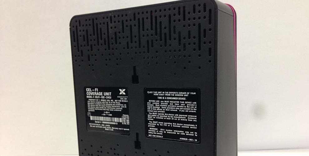
Click to zoom
Application Details
- Equipment Class
- B2P - Part 20 Provider-Specific Consumer Booster (CMRS)
- Date of Grant
- Jul 10, 2014
- Application Purpose
- Original Equipment
- Date of Application
- May 17, 2014
- Equipment Note
- T-Mobile Provider Specific Consumer Signal Booster
- Frequency Range
- 2110.00000000 - 2155.00000000
- Company
- Nextivity Incorporated
- Country
- United States
Documents & Files
Document Text
Text extracted from the exhibit documents filed with the FCC. Open a document above to read the original.
Users Manual
USER MANUAL T-Mobile 4G LTE Signal Booster USER MANUAL T-Mobile 4G LTE Signal Booster Safety Precautions • Use Cel-Fi indoors. It should not be used outdoors. • These products are designed to be used with a direct plug-in power supply unit that shipped with the product. When installing the equipment, all the requirements of the manufacturer and the referenced standards must be met. • There are no user serviceable parts inside. • CAUTION: Changes or modifications to this product not expressly approved by Nextivity may void your right to operate the equipment. FCC Statement This is a CONSUMER device. BEFORE USE, you MUST REGISTER THIS DE- VICE with your wireless provider and have your provider’s consent. Most wireless providers con- sent to the use of signal boosters. Some providers may not consent to the use of this device on their network. If you are unsure, contact your provider. You MUST operate this device with approved an- tennas and cables as specified by the manufac- turer. Antennas MUST be installed at least 20 cm (8 inches) from any person. You MUST cease operating this device immedi- ately if requested by the FCC or a licensed wire- less service provider. WARNING. E911 location information may not be provided or may be inaccurate for calls served by using this device. When used with any mobile device utilizing the 1710-1755 MHz band, the FCC limits booster equipment placement to a maximum of 10 meters above ground level. Installation of this equipment which does not comply with federal requirements may subject the owner to FCC enforcement ac- tion. Changes or modifications not expressly ap- proved by Nextivity, Inc. could void the user’s au- thority to operate the equipment. NOTE: This equipment has been tested and found to comply with the limits for a Class B digital de- vice, pursuant to part 15 of the FCC Rules. These limits are designed to provide reasonable protec- tion against harmful interference in a residential installation. This equipment generates, uses and can radiate radio frequency energy and, if not in- stalled and used in accordance with the instruc- tions, may cause harmful interference to radio communications. However, there is no guarantee that interference will not occur in a particular in- stallation. If this equipment does cause harmful interference to radio or television reception, which can be determined by turning the equipment off and on, the user is encouraged to try to correct the interference by one or more of the following measures: • Reorient or relocate the receiving antenna. • Increase the separation between the equip- ment and receiver. • Connect the equipment into an outlet on a cir- cuit different from that to which the receiver is connected. • Consult the dealer or an experienced radio/TV technician for help Warranty Please refer to the warranty information provided by T-Mobile. Limitation of Liability In no event shall Nextivity, nor its directors, em- ployees, agents, suppliers or End Users, be liable under contract, tort, strict liability, negligence or any other legal or equitable theory with respect to the Products or any other subject matter of this Agreement (i) for any lost profits, cost of procure- ment of substitute goods or services, or special, indirect, incidental, punitive, or consequential damages of any kind whatsoever or (ii) for any direct damages in excess of (in the aggregate) the fees actually received by Nextivity from End User with respect to the Products actually purchased and paid for. Trademark Cel-Fi, IntelliBoost, and Nextivity logo are trade- marks of Nextivity, Inc. Copyright Copyright © 2014 by Nextivity, Inc. All rights re- served. Reproduction or media conversion by any means is protected by copyright and may only oc- cur with prior written permission of Nextivity. Safety Precautions • Use Cel-Fi indoors. It should not be used outdoors. • These products are designed to be used with a direct plug-in power supply unit that shipped with the product. When installing the equipment, all the requirements of the manufacturer and the referenced standards must be met. • There are no user serviceable parts inside. • CAUTION: Changes or modifications to this product not expressly approved by Nextivity may void your right to operate the equipment. FCC Statement This is a CONSUMER device. BEFORE USE, you MUST REGISTER THIS DE- VICE with your wireless provider and have your provider’s consent. Most wireless providers con- sent to the use of signal boosters. Some providers may not consent to the use of this device on their network. If you are unsure, contact your provider. You MUST operate this device with approved an- tennas and cables as specified by the manufac- turer. Antennas MUST be installed at least 20 cm (8 inches) from any person. You MUST cease operating this device immedi- ately if requested by the FCC or a licensed wire- less service provider. WARNING. E911 location information may not be provided or may be inaccurate for calls served by using this device. When used with any mobile device utilizing the 1710-1755 MHz band, the FCC limits booster equipment placement to a maximum of 10 meters above ground level. Installation of this equipment which does not comply with federal requirements may subject the owner to FCC enforcement ac- tion. Changes or modifications not expressly ap- proved by Nextivity, Inc. could void the user’s au- thority to operate the equipment. NOTE: This equipment has been tested and found to comply with the limits for a Class B digital de- vice, pursuant to part 15 of the FCC Rules. These limits are designed to provide reasonable protec- tion against harmful interference in a residential installation. This equipment generates, uses and can radiate radio frequency energy and, if not in- stalled and used in accordance with the instruc- tions, may cause harmful interference to radio communications. However, there is no guarantee that interference will not occur in a particular in- stallation. If…
Text truncated - open the document above for the full version.
Users Manual
Pantone: Black C Pantone: 137C Pantone: 542C For additional information about T-Mobile 4G LTE Signal BoosterInstallation go to: www.T-Mobile.com/SignalBoosterhelp T-Mobile® 4G LTE Signal Booster To use this product you need: • A T-Mobile 3G, 4G or 4G LTE compatible mobile phone • An area inside your home that receives at least one bar of 3G, 4G or 4G LTE coverage • Power outlets WINDOW UNIT COVERAGE UNIT 1 2 4 3 5 Before You Begin. If you can find a place in your home that gets at least one bar of 3G, 4G or 4G LTE signal, the revolutionary NEW T-Mobile 4G LTE Signal Booster system will bring you blazing fast downloads, smoother video and surfing, and improved voice coverage throughout your home. T-Mobile 4G LTE Signal Booster is a true plug-and-play system that doesn’t require the installation of antennas or cables. IMPORTANT: Your T-Mobile 4G LTE Signal Booster is electronic equipment. Both units must be kept indoors and in a dry, cool, well ventilated area. In this package you will find: • Window Unit • Coverage Unit • Two Power Adapters If you need additional information on features and services, visit us at www.t-mobile.com or, using an alternate phone, call us at 1-800-937-8997 This T-Mobile 4G LTE Signal Booster is a T-Mobile-owned device. You will be charged up to $500 if you fail to return the device after termination of your service with T-Mobile, or return it in a damaged condition. IMPORTANT This is a CONsUMER device. BEfORE UsE, you MUsT REGIsTER ThIs dEvICE with your wireless provider and have your provider’s consent. Most wireless providers consent to the use of signal boosters. some providers may not consent to the use of this device on their network. If you are unsure, contact your provider. You MUsT operate this device with approved antennas and cables as specified by the manufacturer. Antennas MUsT be installed at least 20 cm (8 inches) from any person. You MUsT cease operating this device immediately if requested by the fCC or a licensed wireless service provider. WARNING. E911 location information may not be provided or may be inaccurate for calls served by using this device. When used with any mobile device utilizing the 1710-1755 Mhz band, the fCC limits booster equipment placement to a maximum of 10 meters above ground level. Installation of this equipment which does not comply with federal requirements may subject the owner to fCC enforcement action. NOT fOR REsALE. Changes or modifications not expressly approved by Nextivity, Inc. could void the user’s authority to operate the equipment. NOTE: This equipment has been tested and found to comply with the limits for a Class B digital device, pursuant to part 15 of the fCC Rules. These limits are designed to provide reasonable protection against harmful interference in a residential installation. This equipment generates, uses and can radiate radio frequency energy and, if not installed and used in accordance with the instructions, may cause harmful interference to radio communications. however, there is no guarantee that interference will not occur in a particular installation. If this equipment does cause harmful interference to radio or television reception, which can be determined by turning the equipment off and on, the user is encouraged to try to correct the interference by one or more of the following measures: • Reorient or relocate the receiving antenna. • Increase the separation between the equipment and receiver. • Connect the equipment into an outlet on a circuit different from that to which the receiver is connected. • Consult the dealer or an experienced radio/Tv technician for help Coverage is not available everywhere, see coverage details at www.T-Mobile.com. Cel-fi is a trademark of Nextivity, Inc. T-Mobile and the magenta color are registered trademarks of deutsche Telekom AG. ©2014 T-Mobile UsA, Inc. Step 1 Find the location with the best 3G, 4G or 4G LTE coverage: The first step in setting up your T-Mobile 4G LTE Signal Booster system is to find the location in your home or office with the best 3G, 4G or 4G LTE signal. Use your phone to identify the area with the most bars of signal. Typically, the best service will be near a window in the highest floor of your home or office. Make sure a 3G, 4G or 4G LTE icon is displayed on your handset. Step 2 Plug in the Window Unit: Plug the Window Unit into an easily accessible outlet near the area with the strongest 3G, 4G or 4G LTE signal. (Note: both of the power supplies in your kit are identical.) Make sure that at least one bar is displayed on the signal strength indicator on the front of the Window Unit. If you do not see at least one bar, try a different location. WINDOW UNIT LTE WINDOW UNIT DISPLAY 21 Step 4 Place the Coverage Unit: Move to a location in your home where you need to improve coverage. Plug the Coverage Unit into an easily accessible outlet. After several minutes, the numeric display will stop cycling. If your device is set up properly, the green icons will appear on the display as seen above. It is possible to place the Coverage Unit too close or too far from the Window Unit. If this happens, a red icons will illuminate indicating that you need to move the Coverage Unit either closer or further to the Window Unit. T-Mobile 4G LTE Signal Booster Troubleshooting TOO CLOSE A zero on the numeric display indicates that the Coverage Unit needs to be moved farther away from the Window Unit. GOOD Two green icons indicate that the Coverage Unit is functioning normally. TOO FAR four red icons & a scroll- ing display indicate that the Coverage Unit needs to be moved closer to the Window Unit. Step 3 Optimize the Window Unit Placement: The bars on the front of the device indicate the strength of the 3G, 4G or 4G LTE signal in the area. Moving the Window Unit to a different location in your home may increase the signal, and can make a significant difference in the quality of your service. Step 5 Optimize The Coverage Unit Placement:…
Text truncated - open the document above for the full version.
Cover Letter(s)
Nextivity Oscillation Avoidance Technology Per §20.21(e)(9)(ii) (A), Provider Specific Consumer Boosters must employ Anti‐Oscillation strategies. There are two basic ways in which the requirement in this section can be fulfilled. In general, designs would include an oscillation detecting device that would detect when the booster starts to oscillate and would then reduce the gain of the booster in response to stop the oscillation. An alternative implementation, which is used by the Cel‐Fi product, is to prevent the system form ever going into oscillation by monitoring the feedback signal levels and adjusting gain prior to the system entering an oscillation mode. We call this Oscillation Avoidance as opposed to Oscillation Detection. Nextivity’s oscillation avoidance technology is embedded in the custom signal processor chip that forms the heart of all Cel‐Fi products. The signal processor in the Cel‐Fi device measures the isolation between the donor and server antenna in real time while relaying the CMRS signal through the device. This measurement is performed using a real‐time sliding correlator that compares the signal received at the donor input port to the signal that was transmitted at the server port. If the energy level of the signal received from the server port approaches the level where it will cause oscillation, the system gain is immediately reduced. By being able to measure the isolation in real time, the system is able to detect reductions in isolation prior to the isolation dropping below a point where the system can operate without going into oscillation. This means that the system can respond extremely fast to changes in the operating environment and hence never go into oscillation. Furthermore, once a reduction is isolation is detected, the system will adjust its gain immediately and will not increase the gain until such point when the isolation is increased again. In other words, the system can by design never get into a loop where the isolation is decreased, the system starts to oscillate, the gain is reduced, the oscillation stops and then the gain starts to increase again.
RF Exposure Info
Page 1 of 8 Report No: 95395-23A LP100045_RFX Report Form_Rev1 RADIO FREQUENCY EXPOSURE REPORT ADDENDUM TO TEST REPORT 95395-23 Device: Provider Specific Consumer Signal Booster Model: Cel-Fi D32-2/4 Report No.: 95395-23A Date of issue: May 8, 2014 PREPARED FOR: Nextivity, Inc. 12230 World Trade Dr. San Diego CA 92128 PREPARED BY: Eddie Wong CKC Laboratories, Inc. 5046 Sierra Pines Drive Mariposa, CA 95338 The test data contained in this report documents the observed testing parameters pertaining to and are relevant for only the sample equipment tested in the agreed upon operational mode(s) and configuration(s) as identified herein. Compliance assessment remains the client’s responsibility. This report may not be used to claim product endorsement by A2LA or any government agencies. This test report has been authorized for release under quality control from CKC Laboratories, Inc. Steve Behm Director of Quality Assurance & Engineering Services CKC Laboratories, Inc. Page 2 of 8 Report No: 95395-23A Purpose: To demonstrate compliance with United States, Canada and/or European Union RF Exposure requirements for Portable equipment (devices used ≤20cm from the body) or Mobile equipment (devices used >20cm from the body) with power output below exemption levels and Mobile equipment, where Maximum Permissible Exposure (MPE) Calculations apply. United States Compliance Requirements (1.1310): RF Exposure Evaluation Limits Occupational / Controlled Exposure Frequency Range (MHz) Electric Field Strength (V/m) Magnetic Field Strength (A/m) Power Density (mW/cm 2 ) Averaging Time (minutes) 0.3-3.0 614 1.63 *(100) 6 3.0-30 1842/f 4.89/f *(900/f 2 ) 6 30-300 61.4 0.163 1 6 300-1500 --- --- f/300 6 1500-100,000 --- --- 5.0 6 RF Exposure Evaluation Limits General Population / Uncontrolled Exposure Frequency Range (MHz) Electric Field Strength (V/m) Magnetic Field Strength (A/m) Power Density (mW/cm 2 ) Averaging Time (minutes) 0.3-1.34 614 1.63 *(100) 30 1.34-30 824/f 2.19/f *(180/f 2 ) 30 30-300 27.5 0.073 0.2 30 300-1500 --- --- f/1500 30 1500-100,000 --- --- 1.0 30 * Plane wave equivalent power density Limit is calculated based on the mid-band frequency used in the operating frequency range. Exemption Level: Power output <60/f GHz (mW) Page 3 of 8 Report No: 95395-23A Canadian Compliance Requirements (RSS-102): RF Exposure Evaluation Limits Occupational / Controlled Exposure: Frequency Range (MHz) Electric Field Strength (V/m) Magnetic Field Strength (A/m) Power Density (W/m 2 ) Averaging Time (minutes) 0.003-1.0 600 4.9 --- 6 1.0-10 600/f 4.9/f --- 6 10-30 60 4.9/f --- 6 30-300 60 0.163 10 6 300-1500 3.54 f 0.5 0.0094*f 0.5 f/3 6 1500-15,000 137 0.364 50 6 15,000-150,000 137 0.364 50 616000/f 1.2 RF Exposure Evaluation Limits General Population / Uncontrolled Exposure Frequency Range (MHz) Electric Field Strength (V/m) Magnetic Field Strength (A/m) Power Density (W/m 2 ) Averaging Time (minutes) 0.003-1.0 280 2.19 --- 6 1.0-10 280/f 2.19/f --- 6 10-30 28 2.19/f --- 6 30-300 28 0.073 2 6 300-1500 1.585 * f 0.5 0.0042 * f 0.5 f/150 6 1500-15,000 61.4 0.163 10 6 15,000-150,000 61.4 0.163 10 616000/f 1.2 *Power density limit applicable >100MHz Exemption Level: Frequency Range (MHz) Maximum Output Power (Conducted or EIRP) 0.003-1000 ≤ 200 mW 1000-2200 ≤ 100 mW 2200-3000 ≤ 20 mW 3000-6000 ≤ 10 mW Page 4 of 8 Report No: 95395-23A European Union Compliance Requirements (ICNIRP): RF Exposure Evaluation Limits Occupational / Controlled Exposure: Frequency Range (MHz) Electric Field Strength (V/m) Magnetic Field Strength (A/m) Power Density (W/m 2 ) Averaging Time (minutes) 0.00082-0.065 610 24.4 --- 6 0.065-1.0 610 1.6/f --- 1.0-10 610/f 1.6/f --- 6 10-400 61 0.16 10 6 400-2000 3.0 * f 0.5 0.008 * f 0.5 f/40 6 2000-300,000 137 0.36 50 6 RF Exposure Evaluation Limits General Population / Uncontrolled Exposure Frequency Range (MHz) Electric Field Strength (V/m) Magnetic Field Strength (A/m) Power Density (W/m 2 ) Averaging Time (minutes) 0.003-0.150 87 5.0 --- 6 0.150-1.0 87 0.73/f -- 6 1.0-10 87/f 0.5 0.73/f --- 6 10-400 28 0.073 2 6 400-2000 1.375 f 0.5 0.0037*f 0.5 f/200 6 2000-300,000 61 0.16 10 6 *Power density limit applicable >100MHz Exemption Level: Power output < 20mW 1 1 May vary by product type Page 5 of 8 Report No: 95395-23A Device and Antenna Operating Configuration: Device operating at maximum output power with continuous transmission of modulated data. 7.2.2. Maximum Power Measurement of Provider Specific Booster test procedure 935210 D04 Provider Specific Booster Measurement DR06-41704, dated 03/06/2014. Max Gain, Max power. UL= 1850-1915 MHz, 1710-1755MHz, DL= 1930-1995 MHz, 2110-2155MHz. Test Procedure: This equipment is evaluated in accordance with the guidelines set forth in OET Guide 65 & ANSI C95.1 for the US and Health Canada Safety Code 6 & RSS 102 for Canada. Other Considerations: MPE calculation performed with highest EIRP at max power and max antenna gain. Page 6 of 8 Report No: 95395-23A MPE Calculations Applicability: Limit Used X General Population / Uncontrolled Exposure Occupational / Controlled Exposure RF Exposure Exemption No United States NA NA NA NA Equipment operational details: Operating Frequency (MHz) Measured Output Power (dBm) Antenna Gain (dBi) Antenna Type / Configuration EIRP (dBm) 1850-1915 NU 20.1 3 integral 23.1 5150-5350 UNII 16.0 6 integral 22.0 Total 25.6 Operating Frequency (MHz) Measured Output Power (dBm) Antenna Gain (dBi) Antenna Type / Configuration EIRP (dBm) 1710-1755 NU 20.3 2 integral 22.3 5150-5350 UNII 16.0 6 integral 22.0 Total 25.1 Operating Frequency (MHz) Measured Output Power (dBm) Antenna Gain (dBi) Antenna Type / Configuration EIRP (dBm) 2110-2155 CU 11.8 0 integral 11.8 5470-5850 UNII 16.5 6 integral 22.5 5725-5850 DTS 17.7 6 Integral 23.7 Total 26.3 Operating Frequency (MHz) Measured Output Power (dBm) Antenna Gain (dBi) Antenna Type / Configuration EIRP (dBm) 1930-1995 CU 11.2 0 integral 11.2 5470-5850 UNII 16.5 6 integral 22.5 5725-5850 …
Text truncated - open the document above for the full version.
Test Report
This report contains a total of 33 pages and may be reproduced in full only. Partial reproduction may only be done with the written consent of CKC Laboratories, Inc. Nextivity, Inc. ADDENDUM TO TEST REPORT 95395-15 Provider Specific Consumer Signal Booster Model: Cel-Fi D32-2/4 Tested To The Following Standards: FCC PART 24E Report No.: 95395-15A Date of issue: May 8, 2014 This test report bears the accreditation symbol indicating that the testing performed herein meets the test and reporting requirements of ISO/IEC 17025 under the applicable scope of EMC testing for CKC Laboratories, Inc. We strive to create long-term, trust based relationships by providing sound, adaptive, customer first testing services. We embrace each of our customers’ unique EMC challenges, not as an interruption to set processes, but rather as the reason we are in business. Page 2 of 33 Report No.: 95395-15A TABLE OF CONTENTS Administrative Information .......................................................................................................................... 3 Test Report Information ............................................................................................................................................ 3 Revision History ......................................................................................................................................................... 3 Report Authorization ................................................................................................................................................. 3 Test Facility Information ............................................................................................................................................ 4 Software Versions ...................................................................................................................................................... 4 Site Registration & Accreditation Information .......................................................................................................... 4 Summary of Results ................................................................................................................................................... 5 Conditions During Testing.......................................................................................................................................... 5 Equipment Under Test ............................................................................................................................................... 6 Peripheral Devices ..................................................................................................................................................... 6 FCC Part(s) 2 / 24E......................................................................................................................................... 7 2.1047 Modulation Characteristics ............................................................................................................................ 7 2.1049(I) Occupied Bandwidth .................................................................................................................................. 7 2.1051 / 24.238(a) Spurious Emissions at Antenna Terminals ................................................................................ 12 2.1053 / 24.238(a) Field Strength of Spurious Radiation ........................................................................................ 20 2.1055(a)(d) / 24.235 Frequency Stability ............................................................................................................... 25 Supplemental Information .......................................................................................................................... 32 Measurement Uncertainty ...................................................................................................................................... 32 Emissions Test Details .............................................................................................................................................. 32 Page 3 of 33 Report No.: 95395-15A ADMINISTRATIVE INFORMATION Test Report Information REPORT PREPARED FOR: REPORT PREPARED BY: Nextivity, Inc. 12230 World Trade Dr San Diego, CA 92128 Morgan Tramontin CKC Laboratories, Inc. 5046 Sierra Pines Drive Mariposa, CA 95338 Representative: Michiel Lotter Project Number: 95395 Customer Reference Number: 001889 DATE OF EQUIPMENT RECEIPT: March 10, 2014 DATE(S) OF TESTING: March 10 - April 2, 2014 Revision History Original: Testing of the Provider Specific Consumer Signal Booster, Cel-Fi D32-2/4 to FCC Part 24E. Addendum A: To replace all test data, test plots and test setup photos for section 2.1055(a)(d) / 24.235 Frequency Stability. Report Authorization The test data contained in this report documents the observed testing parameters pertaining to and are relevant for only the sample equipment tested in the agreed upon operational mode(s) and configuration(s) as identified herein. Compliance assessment remains the client’s responsibility. This report may not be used to claim product endorsement by A2LA or any government agencies. This test report has been authorized for release under quality control from CKC Laboratories, Inc. Steve Behm Director of Quality Assurance & Engineering Services CKC Laboratories, Inc. Page 4 of 33 Report No.: 95395-15A Test Facility Information Our laboratories are configured to effectively test a wide variety of product types. CKC utilizes first class test equipment, anechoic chambers, data acquisition and information services to create accurate, repeatable and affordable test results. TEST LOCATION(S): CKC Laboratories, Inc. 110 Olinda Place Brea, CA 92823 Software Versions CKC Laboratories Proprietary Software Version EMITest Emissions 5.00.14 Site Registration & Accreditation Information Location CB # TAIWAN CANADA FCC JAPAN Brea A US0060 SL2…
Text truncated - open the document above for the full version.
Test Report
This report contains a total of 36 pages and may be reproduced in full only. Partial reproduction may only be done with the written consent of CKC Laboratories, Inc. Nextivity, Inc. ADDENDUM TO TEST REPORT 95395-17 Provider Specific Consumer Signal Booster Model: Cel-Fi D32-2/4 Tested To The Following Standards: FCC Part 27 Subpart L Report No.: 95395-17A Date of issue: May 8, 2014 This test report bears the accreditation symbol indicating that the testing performed herein meets the test and reporting requirements of ISO/IEC 17025 under the applicable scope of EMC testing for CKC Laboratories, Inc. We strive to create long-term, trust based relationships by providing sound, adaptive, customer first testing services. We embrace each of our customers’ unique EMC challenges, not as an interruption to set processes, but rather as the reason we are in business. Page 2 of 36 Report No.: 95395-17 TABLE OF CONTENTS Administrative Information .......................................................................................................................... 3 Test Report Information ............................................................................................................................................ 3 Revision History ......................................................................................................................................................... 3 Report Authorization ................................................................................................................................................. 3 Test Facility Information ............................................................................................................................................ 4 Software Versions ...................................................................................................................................................... 4 Site Registration & Accreditation Information .......................................................................................................... 4 Summary of Results ................................................................................................................................................... 5 Conditions During Testing.......................................................................................................................................... 5 Equipment Under Test ............................................................................................................................................... 6 Peripheral Devices ..................................................................................................................................................... 6 FCC Part(s) 2 / 27 .......................................................................................................................................... 7 2.1049(I) Occupied Bandwidth .................................................................................................................................. 7 2.1051 /27.53(m) Spurious Emissions at Antenna Terminals .................................................................................. 12 2.1053 / 27.53(m) Field Strength of Spurious Radiation ......................................................................................... 20 2.1055(a)(d) / 27.54 Frequency Stability ................................................................................................................. 28 Supplemental Information .......................................................................................................................... 35 Measurement Uncertainty ...................................................................................................................................... 35 Emissions Test Details .............…
Text truncated - open the document above for the full version.
Contact Information
Applicant
Michiel Lotter(Vice President, Engineering)
Technical Contact
Nextivity IncorporatedMichiel Lotter
[email protected](858) 485-9422
12230 World Trade Drive · San Diego · United States
Non-Technical Contact
CKC Certification Services, LLCRandal Clark
[email protected]209-966-5240
Test Firm
CKC Laboratories, Inc.Steve Behm
Technical Specifications
| # | Rule Parts | Frequency Range | Power Output | Emission | Tolerance |
|---|---|---|---|---|---|
| 4 | 27 | 2.11 GHz - 2.15 GHz | 15.00 mW | W7D | 0.0012 % |
Other Applications from Nextivity Incorporated
YETA91-JV4
Sep 12, 2024Smart Server Antenna
Equipment Class
DTS - Digital Transmission System
YETG41-CE
Jan 10, 2024Cellular Signal Booster with BLE
Equipment Class
B2I - Part 20 Industrial Booster (CMRS)
YETA71-JV4
Oct 02, 2023Smart Server Antenna
Equipment Class
DTS - Digital Transmission System
YETQ42-Z1CNU
May 05, 2023Provider-Specific Consumer Signal Booster
Equipment Class
B2P - Part 20 Provider-Specific Consumer Booster (CMRS)
YETQ41-BXCU
May 05, 2023Provider-Specific Consumer Signal Booster
Equipment Class
B2P - Part 20 Provider-Specific Consumer Booster (CMRS)