YETP24512NUProvider Specific Consumer Signal Booster
Nextivity Incorporated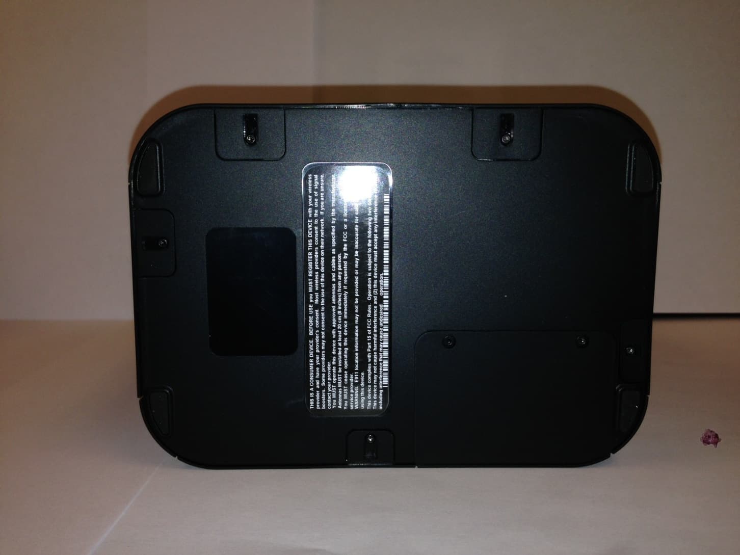
Click to zoom
Application Details
- Equipment Class
- NII - Unlicensed National Information Infrastructure TX
- Date of Grant
- Sep 02, 2014
- Application Purpose
- Original Equipment
- Date of Application
- Aug 04, 2014
- Equipment Note
- Provider Specific Consumer Signal Booster
- Frequency Range
- 5260.00000000 - 5293.00000000
- Company
- Nextivity Incorporated
- Country
- United States
Documents & Files
Document Text
Text extracted from the exhibit documents filed with the FCC. Open a document above to read the original.
Users Manual
Note: the brackets come equipped with screws and inserts for mounting in stan- dard drywall. Before you install the mounts, make sure there are no wires or other objects, or metal plates, behind the drywall layer that will interfere with the in- serts, screws, or mount, or mounted units. Note: the Network Unit only has mounting holes on the back. the Coverage Unit has mounting holes on the bottom and on the back. the holes on the bottom of the Coverage Unit can be used for mounting the Coverage Unit on a ceiling. (See 6b) RequiRed HaRdwaRe Copyright © 2014 by Nextivity, inc, u.S. Patents pending. all rights reserved. the Nextivity and Cel-Fi logos are registered trademarks of Nextivity inc. all other trademarks or registered trademarks listed belong to their respective owners. designed by Nextivity inc in California. each Cel-Fi device may be supplied with mounting brackets and hardware to mount both (or either) the Coverage Unit and the Network Unit. form-bracket-PRo-english_14-0515 Mounting Instructions for Cel-Fi PRO For more information, refer to the Quick Start Guide or visit www.cel-fi.com CEL-FI PRO SMART SIGNAL BOOSTER 6 Attach the Cel-Fi Unit to the wall mounted bracket. 6b Optional: Attach the Cel-Fi Unit to a ceiling mounted bracket. Network Unit Coverage Unit For more information, visit www.Cel-Fi.com Network Unit Coverage Unit To ensure ceiling mounting is as secure as possible, confirm that the mounting bracket posts are firmly inserted, and in the correct position. (x4) Coverage Unit upside down (x4) Slide Coverage Unit until secure. Mounting Posts Figure 1. Coverage Unit, back view with mounting holes. Figure 2. Coverage Unit, bottom view of mounting holes. Figure 3. Network Unit, back view of mounting holes. For more information, refer to the Quick Start Guide or visit www.cel-fi.com CEL-FI PRO SMART SIGNAL BOOSTER Coverage Unit Back Mounting Holes Coverage Unit Bottom Mounting Holes Network (Window) Unit Back Mounting Holes 1 Determine Cel-Fi Device Location (refer to Quick Start Guide) 2 Determine Mounting Hole Locations 3 Drill Anchor Holes (Drywall) 4 Install Anchors (Drywall) 3G/4G /LTE Network Unit Coverage Unit in each marked spot, use a 3/16” drill bit to drill guide holes for the anchors. 5 Install Mounting Bracket
Users Manual
PRODUCT INFORMATION Cel-Fi ® PRO Smart Signal Booster PRODUCT INFORMATION Cel-Fi PRO ® Smart Signal Booster If you need help, visit: http://www.celfihelp.com Safety Precautions • Use Cel-Fi indoors. It should not be used outdoors. • These products are designed to be used with a direct plug-in power supply unit that shipped with the product. When installing the equipment, all the requirements of the manufacturer and the referenced standards must be met. • There are no user serviceable parts inside. • CAUTION: Changes or modifications to this product not expressly approved by Nextivity may void your right to operate the equipment. Warranty Nextivity Inc provides a limited warranty for its products. For details, please refer to http://cel-fi. com/warranty. Limitation of Liability In no event shall Nextivity, nor its directors, employees, agents, suppliers or End Users, be liable under contract, tort, strict liability, negli- gence or any other legal or equitable theory with respect to the Products or any other subject mat- ter of this Agreement (i) for any lost profits, cost of procurement of substitute goods or services, or special, indirect, incidental, punitive, or con- sequential damages of any kind whatsoever or (ii) for any direct damages in excess of (in the aggregate) the fees actually received by Nextiv- ity from End User with respect to the Products actually purchased and paid for. See celfi.com for list of patents covering this product. Trademark Cel-Fi, IntelliBoost, and Nextivity logo are trade- marks of Nextivity, Inc. FCC Statement This is a CONSUMER device. BEFORE USE, you MUST REGISTER THIS DEVICE with your wireless provider and have your provider’s consent. Most wireless providers consent to the use of signal boosters. Some pro- viders may not consent to the use of this device on their network. If you are unsure, contact your provider. You MUST operate this device with approved antennas and cables as specified by the manu- facturer. Antennas MUST be installed at least 20 cm (8 inches) from any person. You MUST cease operating this device immedi- ately if requested by the FCC or a licensed wire- less service provider. WARNING. E911 location information may not be provided or may be inaccurate for calls served by using this device. When used with any mobile device utilizing the 1710-1755 MHz band, the FCC limits booster equipment placement to a maximum of 10 me- ters above ground level. Installation of this equipment which does not comply with federal requirements may subject the owner to FCC en- forcement action. This device complies with part 15 of the FCC Rules. Operation is subject to the following two conditions: (1) This device may not cause harmful interference, and (2) this device must accept any interference received, including interference that may cause undesired operation. NOTE: This equipment has been tested and found to comply with the limits for a Class B digi- tal device, pursuant to part 15 of the FCC Rules. These limits are designed to provide reasonable protection against harmful interference in a resi- If you need help, visit: http://www.celfihelp.com Safety Precautions • Use Cel-Fi indoors. It should not be used outdoors. • These products are designed to be used with a direct plug-in power supply unit that shipped with the product. When installing the equipment, all the requirements of the manufacturer and the referenced standards must be met. • There are no user serviceable parts inside. • CAUTION: Changes or modifications to this product not expressly approved by Nextivity may void your right to operate the equipment. Warranty Nextivity Inc provides a limited warranty for its products. For details, please refer to http://cel-fi. com/warranty. Limitation of Liability In no event shall Nextivity, nor its directors, employees, agents, suppliers or End Users, be liable under contract, tort, strict liability, negli- gence or any other legal or equitable theory with respect to the Products or any other subject mat- ter of this Agreement (i) for any lost profits, cost of procurement of substitute goods or services, or special, indirect, incidental, punitive, or con- sequential damages of any kind whatsoever or (ii) for any direct damages in excess of (in the aggregate) the fees actually received by Nextiv- ity from End User with respect to the Products actually purchased and paid for. See celfi.com for list of patents covering this product. Trademark Cel-Fi, IntelliBoost, and Nextivity logo are trade- marks of Nextivity, Inc. FCC Statement This is a CONSUMER device. BEFORE USE, you MUST REGISTER THIS DEVICE with your wireless provider and have your provider’s consent. Most wireless providers consent to the use of signal boosters. Some pro- viders may not consent to the use of this device on their network. If you are unsure, contact your provider. You MUST operate this device with approved antennas and cables as specified by the manu- facturer. Antennas MUST be installed at least 20 cm (8 inches) from any person. You MUST cease operating this device immedi- ately if requested by the FCC or a licensed wire- less service provider. WARNING. E911 location information may not be provided or may be inaccurate for calls served by using this device. When used with any mobile device utilizing the 1710-1755 MHz band, the FCC limits booster equipment placement to a maximum of 10 me- ters above ground level. Installation of this equipment which does not comply with federal requirements may subject the owner to FCC en- forcement action. This device complies with part 15 of the FCC Rules. Operation is subject to the following two conditions: (1) This device may not cause harmful interference, and (2) this device must accept any interference received, including interference that may cause undesired operation. NOTE: This equipment has been tested and found to comply with the limits for a Class B digi- tal device, pursuant to part 15 of the FCC Rules. These limits are designed…
Text truncated - open the document above for the full version.
Users Manual
CEL-FI PRO Quick Start Guide Troubleshooting The key to better performance is the placement of the two units. FCC Requirements: This is a CONSUMER device. BEFORE USE, you MUST REGISTER THIS DEVICE with your wireless provider and have your provider’s consent. Most wireless providers consent to the use of signal boosters. Some providers may not consent to the use of this device on their network. If you are unsure, contact your provider. You MUST operate this device with approved antennas and cables as speci ed by the manufacturer. Antennas MUST be installed at least 20 cm (8 inches) from any person. You MUST cease operating this device immediately if requested by the FCC or a licensed wireless service provider. WARNING. E911 location information may not be provided or may be inaccurate for calls served by using this device. When used with any mobile device utilizing the 1710-1755 MHz band, the FCC limits booster equipment placement to a maximum of 10 meters above ground level. Installation of this equipment which does not comply with federal requirements may subject the owner to FCC enforcement action. NOT FOR RESALE. Changes or modi cations not expressly approved by Nextivity, Inc. could void the user’s authority to operate the equipment. NOTE: This equipment has been tested and found to comply with the limits for a Class B digital device, pursuant to part 15 of the FCC Rules. These limits are designed to provide reasonable protection against harmful interference in a residential installation. This equipment generates, uses and can radiate radio frequency energy and, if not installed and used in accordance with the instructions, may cause harmful interference to radio communications. However, there is no guarantee that interference will not occur in a particular installation. If this equipment does cause harmful interference to radio or television reception, which can be determined by turning the equipment o and on, the user is encouraged to try to correct the interference by one or more of the following measures: • Reorient or relocate the receiving antenna. • Increase the separation between the equipment and receiver. • Connect the equipment into an outlet on a circuit different from that to which the receiver is connected. • Consult the dealer or an experienced radio/TV technician for help Copyright © 2014 by Nextivity, Inc, U.S. Patents pending. All rights reserved. The Nextivity and Cel-Fi logos are registered trademarks of Nextivity Inc. All other trademarks or registered trademarks listed belong to their respective owners. Designed by Nextivity in California. For more information, visit www.Cel-Fi.com. qsg-PRO-NA-English_14-0507 Reset the Network Unit by unplug- ging it and then plugging it back in. If the problem persists, return system for service replacement. Try resetting the Coverage Unit by unplugging it and then plugging it back in. If problem persists, return system for service. The signal from the wireless network is too strong to use a booster. Make sure that the vents (the small openings in the plastic housing) on the units are not blocked. Move the unit to a cooler area. The system will start working normally when it cools down. Make sure that the vents (the small openings in the plastic housing) on the units are not blocked. Move the unit to a cooler area. The system will start working normally when it cools down. Try moving the units farther apart.Try moving the units closer together. Please call your cell phone provider. UI Help (Error 7) Unit disabled by networkThe units are too far apart The units are too close together (Error 8) Input signal too strong (Error 4) NU is overheating(Error 3) CU is overheating (Error 6) NU Hardware Error(Error 1) Not receiving signal(Error 2) CU Hardware Error Relocate the Network Unit to another room or area where you have more coverage. (Use your cell phone to nd the best cellular signal). Box Contents: • Quick Start Guide • Network Unit • Coverage Unit • Power Adapters (2) • Mounting Brackets (2) If you have followed the install procedures and are still seeking improved coverage, please visit the Troubleshooting on the reverse side of the Quick Start Guide. For more information and videos, please visit cel-fi.com. Find the best cellular signal. For Cel-Fi PRO to work correctly, you need to have either a 3G, 4G or LTE signal. Typically, you will get the best signal upstairs near a window. Step 1 Place the Coverage Unit (CU). Place the CU in the location where you need improved coverage. Step 3 Place the Network Unit (NU). Place the NU in the location where you get the best cellular signal. Step 2 Optimize Coverage. For best results, try moving the CU around to a few different spots. Typically, the farther the units are apart, the better coverage you will have. Although, it is possible to move the units too far apart. Step 4 Network Unit 2 Bars 3 Bars 5 bars! T oo Far Cel-Fi Quick Start Guide Follow these simple steps for a quick and easy set-up. 3G/4G/L TE 3G/4G/L TE 3G/4G/L TE Network UnitCoverage Unit T oo Close User Interface LCD Screen On/Off Button for LCD Backlighting Coverage UnitCoverage UnitCoverage UnitCoverage Unit Coverage Unit
Cover Letter(s)
12230 World Trade Drive Suite 250 San Diego California 92128 858.485.9442 (main) 858-485.9445 (fax) [email protected] www.nextivityinc.com 17 June 2014 Federal Communications Commission 7435 Oakland Mills Road Columbia, MD 21046 Subject: Request for Permanent Confidentiality To whom it may concern: In accordance with 47CFR Section 0.457 and Section 0.459 pertaining to confidential material, we hereby request to hold permanently confidential all information contained within the below identified exhibits/document categories submitted pursuant to radio equipment certification requirements for FCC ID: YETP24512NU and YETP24512CU • Block diagrams (P34-2_4_5_12 Block Diagram.pdf) • BOMs • Schematics (600N300-415-001.pdf and 600N300-415-002.pdf) • Theory of operation (Cel-Fi P34-2_4_5_12 Operational Description FCC.pdf and Nextivity Oscillation Avoidance Technology.pdf) • Factory Tuning Procedure (Tune-up.pdf) The above material contains trade secrets and proprietary information as specified by 47CFR 0.457(d) and technical data, which would customarily be guarded from competitors. The public disclosure of this information might be harmful to our company and provide unjustified benefits to our competitors. Sincerely, Michiel Lotter CTO & Vice‐President Engineering Nextivity Inc. 12230 World Trade Dr. #250 San Diego, CA 92128 (858) 485‐9442
Cover Letter(s)
1 Mark Briggs From: Andrew Leimer [[email protected]] Sent: Wednesday, February 25, 2009 12:56 PM To: Mark Briggs Subject: FW: Nextivity - Alternative Streaming Method and Test Plan Nextivity has been approved. Andy ‐‐‐‐‐Original Message‐‐‐‐‐ From: Robert Sole [mailto:[email protected]] Sent: Wednesday, February 25, 2009 10:51 AM To: Andrew Leimer; John carrol; Ed Drocella Cc: John Philpott; Robert Sole Subject: RE: Nextivity ‐ Alternative Streaming Method and Test Plan Hi Andy, I have reviewed the document from Nextivity titled "DFS Implementation Proposal for Cel‐Fi U‐NII Link" Version 0.7 dated February 23, 2009. My review of the document shows that they have made the necessary changes to the previous version as requested by NTIA, therefore we give approval of their proposal on how to test their U‐NII device. Since this is a new type of U‐NII device, NTIA would like to see the results of their testing once they have been completed. If the devices are tested in the FCC Columbia Laboratory, NTIA would like to witness some of the testing. I will also send a summary letter to the TSC Chairman of this approval for record keeping purposes. Robert Sole Spectrum Engineering Branch Chief Office of Spectrum Management NTIA/USDOC, Washington DC Phone 202 482‐1245 Fax 202 482‐4595 [email protected]
Cover Letter(s)
12230 World Trade Drive Suite 250 San Diego California 92128 858.485.9442 (main) 858-485.9445 (fax) [email protected] www.nextivityinc.com 17 June, 2014 Federal Communications Commission 7435 Oakland Mills Road Columbia, MD 21046 FCC ID: YETP24512NU and YETP24512CU Gentlemen: This is your letter of authorization to accept our appointment of CKC CS as Agent for Nextivity Inc., 12230 World Trade Drive, Suite 250, San Diego, CA, U.S.A, to sign applications before the Commission and to make representations to you on our behalf. CKC CS is to receive and exchange data between our company and the Commission. This authorization is made pursuant to Section 2.911(c) of the FCC Rules and expires on 12/31/2014. I hereby certify on behalf of Nextivity Incorporated, 12230 World Trade Drive, Suite 250, San Diego, CA, U.S.A. ("Applicant") that neither Applicant nor any party to the application (officers, directors, and 5% shareholders) is subject to a denial of Federal benefits that includes FCC benefits pursuant to section 5301 of the Anti-Drug Abuse Act of 1988. 21 U.S.C. 853a. Sincerely, Michiel Lotter CTO & V.P. Engineering, Nextivity
Cover Letter(s)
12230 World Trade Drive Suite 250 San Diego California 92128 858.485.9442 (main) 858-485.9445 (fax) [email protected] www.nextivityinc.com 3 September, 2014 Federal Communications Commission 7435 Oakland Mills Road Columbia, MD 21046 To Whom It May Concern: RE: Request for expedited review for FCC ID YETP24512NU and YETP24512CU We hereby respectfully request that Expedited Review of the DFS capabilities of the Cel‐Fi P34‐2/4/5/12 Provider Specific Consumer Signal Booster. This DFS operation of this signal booster has already been reviewed for DFS conformance under FCC ID’s YETD24NU and YETD24CU. The Cel‐Fi P34‐2/4/5/12 uses the identical RF and processing chains for DFS operation as the already approved Cel‐Fi D32‐2/4 product that was reviewed and tested by OET. Sincerely, Michiel Lotter CTO & V.P. Engineering, Nextivity
External Photos
NU external
RF Exposure Info
Page 1 of 11 Report No: 95128-32 RADIO FREQUENCY EXPOSURE REPORT FOR THE Device: Provider Specific Consumer Signal Booster Model: Cel-Fi P34-2/4/5/12 Report No.: 95128-32 Date of issue: May 23, 2014 PREPARED FOR: Nextivity, Inc. 12230 World Trade Dr. San Diego, CA 92128 PREPARED BY: Eddie Wong CKC Laboratories, Inc. 5046 Sierra Pines Drive Mariposa, CA 95338 The test data contained in this report documents the observed testing parameters pertaining to and are relevant for only the sample equipment tested in the agreed upon operational mode(s) and configuration(s) as identified herein. Compliance assessment remains the client’s responsibility. This report may not be used to claim product endorsement by A2LA or any government agencies. This test report has been authorized for release under quality control from CKC Laboratories, Inc. Steve Behm Director of Quality Assurance & Engineering Services CKC Laboratories, Inc. Page 2 of 11 Report No: 95128-32 Purpose: To demonstrate compliance with United States, Canada and/or European Union RF Exposure requirements for Portable equipment (devices used ≤20cm from the body) or Mobile equipment (devices used >20cm from the body) with power output below exemption levels and Mobile equipment, where Maximum Permissible Exposure (MPE) Calculations apply. United States Compliance Requirements (1.1310): RF Exposure Evaluation Limits Occupational / Controlled Exposure: Frequency Range (MHz) Electric Field Strength (V/m) Magnetic Field Strength (A/m) Power Density (mW/cm 2 ) Averaging Time (minutes) 0.3-3.0 614 1.63 *(100) 6 3.0-30 1842/f 4.89/f *(900/f 2 ) 6 30-300 61.4 0.163 1 6 300-1500 --- --- f/300 6 1500-100,000 --- --- 5.0 6 RF Exposure Evaluation Limits General Population / Uncontrolled Exposure: Frequency Range (MHz) Electric Field Strength (V/m) Magnetic Field Strength (A/m) Power Density (mW/cm 2 ) Averaging Time (minutes) 0.3-1.34 614 1.63 *(100) 30 1.34-30 824/f 2.19/f *(180/f 2 ) 30 30-300 27.5 0.073 0.2 30 300-1500 --- --- f/1500 30 1500-100,000 --- --- 1.0 30 * Plane wave equivalent power density Limit is calculated based on the mid-band frequency used in the operating frequency range. Exemption Level: Power output <60/f GHz (mW) Page 3 of 11 Report No: 95128-32 Canadian Compliance Requirements (RSS-102): RF Exposure Evaluation Limits Occupational / Controlled Exposure: Frequency Range (MHz) Electric Field Strength (V/m) Magnetic Field Strength (A/m) Power Density (W/m 2 ) Averaging Time (minutes) 0.003-1.0 600 4.9 --- 6 1.0-10 600/f 4.9/f --- 6 10-30 60 4.9/f --- 6 30-300 60 0.163 10 6 300-1500 3.54 f 0.5 0.0094*f 0.5 f/3 6 1500-15,000 137 0.364 50 6 15,000-150,000 137 0.364 50 616000/f 1.2 RF Exposure Evaluation Limits General Population / Uncontrolled Exposure: Frequency Range (MHz) Electric Field Strength (V/m) Magnetic Field Strength (A/m) Power Density (W/m 2 ) Averaging Time (minutes) 0.003-1.0 280 2.19 --- 6 1.0-10 280/f 2.19/f --- 6 10-30 28 2.19/f --- 6 30-300 28 0.073 2 6 300-1500 1.585 * f 0.5 0.0042 * f 0.5 f/150 6 1500-15,000 61.4 0.163 10 6 15,000-150,000 61.4 0.163 10 616000/f 1.2 *Power density limit applicable >100MHz Exemption Level: Frequency Range (MHz) Maximum Output Power (Conducted or EIRP) 0.003-1000 ≤ 200 mW 1000-2200 ≤ 100 mW 2200-3000 ≤ 20 mW 3000-6000 ≤ 10 mW Page 4 of 11 Report No: 95128-32 European Union Compliance Requirements (ICNIRP): RF Exposure Evaluation Limits Occupational / Controlled Exposure: Frequency Range (MHz) Electric Field Strength (V/m) Magnetic Field Strength (A/m) Power Density (W/m 2 ) Averaging Time (minutes) 0.00082-0.065 610 24.4 --- 6 0.065-1.0 610 1.6/f --- 1.0-10 610/f 1.6/f --- 6 10-400 61 0.16 10 6 400-2000 3.0 * f 0.5 0.008 * f 0.5 f/40 6 2000-300,000 137 0.36 50 6 RF Exposure Evaluation Limits General Population / Uncontrolled Exposure: Frequency Range (MHz) Electric Field Strength (V/m) Magnetic Field Strength (A/m) Power Density (W/m 2 ) Averaging Time (minutes) 0.003-0.150 87 5.0 --- 6 0.150-1.0 87 0.73/f -- 6 1.0-10 87/f 0.5 0.73/f --- 6 10-400 28 0.073 2 6 400-2000 1.375 f 0.5 0.0037*f 0.5 f/200 6 2000-300,000 61 0.16 10 6 *Power density limit applicable >100MHz Exemption Level: Power output < 20mW 1 1 May vary by product type Page 5 of 11 Report No: 95128-32 Device and Antenna Operating Configuration: The device is operating at maximum output power with continuous transmission of modulated data. 7.2.2. Maximum Power Measurement of Provider Specific Booster test procedure 935210 D04 Provider Specific Booster Measurement DR06-41704 dated 03/06/2014. Max Gain, Max power. UL= 698-716MHz, 824-849MHz, 1850-1915 MHz, 1710-1755MHz DL= 716-746MHz, 869-894MHz, 1930-1990 MHz, 2110-2155MHz Test Procedure: This equipment is evaluated in accordance with the guidelines set forth in OET Guide 65 & ANSI C95.1 for the US and Health Canada Safety Code 6 & RSS 102 for Canada. Other Considerations: None or Delete “none & Insert specific Page 6 of 11 Report No: 95128-32 MPE Calculations Applicability Limit Used X General Population / Uncontrolled Exposure Occupational / Controlled Exposure RF Exposure Exemption NO United States NA Canada NA Europe Equipment Operational Details Measurements taken from EMC Test Report(s): R95054 ( DTS), R95055 (UNII) 95128-15 ( Part 20). In operation, the device can maintain a link either with UNII frequency band or DTS frequency band, from the test reports, the measured power of DTS band is the worst case. The calculation is based on Power measured from Part 20 report 95128-15 and DTS band report R95054. Page 7 of 11 Report No: 95128-32 Freq Range Meas Power (dBm) Antenna Gain (dBi) Antenna Type EIRP (dBm) EIRP (mW) US mW/cm 2 UL 1710-1755 21.50 4.00 Internal 2.55E+01 354.81 1.00 DTS 5725-5820 19.40 6.00 Internal 2.54E+01 346.74 1.00 Total 701.55 dBm 28.46 Freq Range Meas Power (dBm) Antenna Gain (dBi) Antenna Type EIRP (dBm) EIRP (mW) US mW/cm 2 UL 1850-1915 22.10 5.00 Internal 2.71E+01 512.86 1.00 DTS 5725-5820 19.40 6.00 Internal 2.54E+01 346.74 1.00 Total 859.60…
Text truncated - open the document above for the full version.
Test Report
File: R94497 Rev 3 Page 1 of 281 TEST REPORT Covering the DYNAMIC FREQUENCY SELECTION (DFS) REQUIREMENTS OF FCC Part 15 Subpart E (UNII), RSS-210 Annex 9 Nextivity Inc. Model(s): P34-2/4/5/12NU and P34-2/4/5/12CU COMPANY: Nextivity Inc. 12230 World Trade Drive, Suite 250 San Diego, CA, 92128 TEST SITE: National Technical Systems - Silicon Valley 41039 Boyce Road Fremont, CA 94538 REPORT DATE: April 3, 2014 REISSUE DATE: August 1, 2014 FINAL TEST DATE: December 19, 23, 31, 2013 and January 2, 2014 TEST ENGINEER: Michael Findley TOTAL NUMBER OF PAGES: 281 National Technical Systems - Silicon Valley is accredited by the A2LA, certificate number 0214.26, to perform the test(s) listed in this report, except where noted otherwise. This report and the information contained herein represent the results of testing test articles identified and selected by the client performed to specifications and/or procedures selected by the client. National Technical Systems (NTS) makes no representations, expressed or implied, that such testing is adequate (or inadequate) to demonstrate efficiency, performance, reliability, or any other characteristic of the articles being tested, or similar products. This report should not be relied upon as an endorsement or certification by NTS of the equipment tested, nor does it represent any statement whatsoever as to its merchantability or fitness of the test article, or similar products, for a particular purpose. This report shall not be reproduced except in full NTS Silicon Valley -- EMC Department Test Report Report Date: April 3, 2014 Reissue Date: August 1, 2014 File: R94497 Rev 3 Page 2 of 281 VALIDATING SIGNATORIES PROGRAM MGR / TECHNICAL REVIEWER: ______________________________ David W. Bare Chief Engineer REPORT PREPARER: ______________________________ Michael Findley Senior Engineer QUALITY ASSURANCE DELEGATE ______________________________ David Guidotti Senior Technical Writer NTS Silicon Valley -- EMC Department Test Report Report Date: April 3, 2014 Reissue Date: August 1, 2014 File: R94497 Rev 3 Page 3 of 281 REVISION HISTORY Rev # Date Comments Modified By - April 3, 2014 Initial Release 1 April 9, 2014 Reissued to update model name to P34-2/4/5/12NU and P34-2/4/5/12CU from CU and NU Dave Guidotti 2 May 7, 2014 Added statement about random selection with uniform distribution for each of the variable parameters on page 24. Added plot of SA noise floor during testing on page 25. Added additional information about radar generator radar pulse calibration on pages 26-31. David Bare 3 August 1, 2014 Added statement concerning antenna polarization on pages 22 and 24, removed reference to EN 301 893 waveform on pages 268-270, added photo of radar generating equipment on page 280. David Bare NTS Silicon Valley -- EMC Department Test Report Report Date: April 3, 2014 Reissue Date: August 1, 2014 File: R94497 Rev 3 Page 4 of 281 TABLE OF CONTENTS TITLE PAGE .............................................................................................................................................. 1 VALIDATING SIGNATORIES ................................................................................................................................ 2 REVISION HISTORY ................................................................................................................................................ 3 TABLE OF CONTENTS ............................................................................................................................................ 4 LIST OF TABLES ....................................................................................................................................................... 5 LIST OF FIGURES ..................................................................................................................................................... 9 SCOPE ........................................................................................................................................................................ 11 OBJECTIVE .............................................................................................................................................................. 11 STATEMENT OF COMPLIANCE ......................................................................................................................... 11 DEVIATIONS FROM THE STANDARD .............................................................................................................. 11 TEST RESULTS ........................................................................................................................................................ 12 TEST RESULTS SUMMARY – FCC PART 15, MASTER DEVICE ................................................................... 12 MEASUREMENT UNCERTAINTIES .................................................................................................................. 17 EQUIPMENT UNDER TEST (EUT) DETAILS .................................................................................................... 18 GENERAL .............................................................................................................................................................. 18 ENCLOSURE ......................................................................................................................................................... 19 MODIFICATIONS ................................................................................................................................................. 20 SUPPORT EQUIPMENT ....................................................................................................................................... 20 EUT INTERFACE PORTS ........................................................................................…
Text truncated - open the document above for the full version.
Contact Information
Applicant
Michiel Lotter(Vice President, Engineering)
Non-Technical Contact
CKC Certification Services, LLCRandal Clark
[email protected]209-966-5240
Test Firm
Element Materials Technology Fremont NewarkDavid Bare
Technical Specifications
| # | Rule Parts | Frequency Range | Power Output |
|---|---|---|---|
| 2 | 15E | 5.26 GHz - 5.29 GHz | 49.00 mW |
Other Applications from Nextivity Incorporated
YETA91-JV4
Sep 12, 2024Smart Server Antenna
Equipment Class
DTS - Digital Transmission System
YETG41-CE
Jan 10, 2024Cellular Signal Booster with BLE
Equipment Class
B2I - Part 20 Industrial Booster (CMRS)
YETA71-JV4
Oct 02, 2023Smart Server Antenna
Equipment Class
DTS - Digital Transmission System
YETQ42-Z1CNU
May 05, 2023Provider-Specific Consumer Signal Booster
Equipment Class
B2P - Part 20 Provider-Specific Consumer Booster (CMRS)
YETQ41-BXCU
May 05, 2023Provider-Specific Consumer Signal Booster
Equipment Class
B2P - Part 20 Provider-Specific Consumer Booster (CMRS)