YETQ34-2121466NUProvider-Specific Consumer Signal Booster
Nextivity Incorporated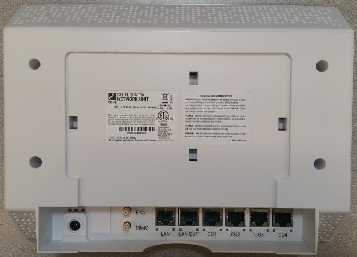
Click to zoom
Application Details
- Equipment Class
- B9B - Part 90 Class B Industrial Booster (non-SMR)
- Date of Grant
- Nov 16, 2020
- Application Purpose
- Original Equipment
- Date of Application
- Nov 16, 2020
- Equipment Note
- Provider-Specific Consumer Signal Booster
- Frequency Range
- 788.00000000 - 798.00000000
- Company
- Nextivity Incorporated
- Country
- United States
Documents & Files
Document Text
Text extracted from the exhibit documents filed with the FCC. Open a document above to read the original.
Users Manual
Warranty Nextivity Inc provides a limited warranty for its products. For details, please refer to http://cel-fi.com/ warranty. Limitation of Liability In no event shall Nextivity, nor its directors, employees, agents, suppliers or End Users, be liable under contract, tort, strict liability, negligence or any other legal or equitable theory with respect to the Products or any other subject matter of this Agreement (i) for any lost profits, cost of procurement of substitute goods or services, or special, indirect, incidental, punitive, or consequential damages of any kind whatsoever or (ii) for any direct damages in excess of (in the aggregate) the fees actually received by Nextivity from End User with respect to the Products actually purchased and paid for. See cel-fi.com for list of patents covering this product. Trademark Cel-Fi, IntelliBoost, and Nextivity logo are trademarks of Nextivity, Inc. FCC Part 90 and Part 20 Signal Boosters. THIS IS A 90.219 CLASS B DEVICE WARNING. This is NOT a CONSUMER device. It is designed for installation by FCC LICENSEES and QUALIFIED INSTALLERS. You MUST have an FCC LICENSE or express consent of an FCC License to operate this device. You MUST register Part 90 Class B signal boosters (as defined in 47 CFR 90.219) online at www.fcc.gov/signal-boosters/registration. Unauthorized use may result in significant forfeiture penalties, including penalties in excess of $100,000 for each continuing violation. Safety Precautions •Use Cel-Fi indoors. It should not be used outdoors. •These products are designed to be used with a direct plug-in power supply unit that shipped with the Network Unit. When installing the equipment, all the requirements of the manufacturer and the referenced standards must be met. • Ther e are no user serviceable parts inside. • CAUTION: Changes or modifications to this product not expressly approved by Nextivity may void your right to operate the equipment. WARNING. This is NOT a CONSUMER device. It is designed for installation by FCC LICENSEES and QUALIFIED INSTALLERS. You MUST have an FCC L ICENSE or express consent of an FCC License to operate this device. You MUST register Part 90 Class B signal boosters (as defined in 47 CFR 90.219) online at www.fcc.gov/signal-boosters/registration. Unauthorized use may result in significant forfeiture penalties, including penalties in excess of $100,000 for each continuing violation. WARNING: In order to comply with FCC RF Exposure requirements, all antennas must be installed to provide at least 20 cm separation from the human body at all times. External Antenna You MUST operate this device with approved antennas and cables as specified by the manufacturer. Only the antennas listed in the Antenna Kitting section of the Quick Start Guide are allowed to be used with Cel-Fi Smart Signal Boosters. FCC Statement When used with any mobile device utilizing the 1710-1755 MHz band, the FCC limits booster equipment placement to a maximum of 10 meters above ground level. Installation of this equipment which does not comply with federal requirements may subject the owner to FCC enforcement action. This device complies with part 15 of the FCC Rules. Operation is subject to the following two conditions: (1) This device may not cause harmful interference, and (2) this device must accept any interference received, including interference that may cause undesired operation. NOTE: This equipment has been tested and found to comply with the limits for a Class B digital device, pursuant to part 15 of the FCC Rules. These limits are designed to provide reasonable protection against Warranty Nextivity Inc provides a limited warranty for its products. For details, please refer to http://cel-fi.com/ warranty. Limitation of Liability In no event shall Nextivity, nor its directors, employees, agents, suppliers or End Users, be liable under contract, tort, strict liability, negligence or any other legal or equitable theory with respect to the Products or any other subject matter of this Agreement (i) for any lost profits, cost of procurement of substitute goods or services, or special, indirect, incidental, punitive, or consequential damages of any kind whatsoever or (ii) for any direct damages in excess of (in the aggregate) the fees actually received by Nextivity from End User with respect to the Products actually purchased and paid for. See cel-fi.com for list of patents covering this product. Trademark Cel-Fi, IntelliBoost, and Nextivity logo are trademarks of Nextivity, Inc. FCC Part 90 and Part 20 Signal Boosters. THIS IS A 90.219 CLASS B DEVICE WARNING. This is NOT a CONSUMER device. It is designed for installation by FCC LICENSEES and QUALIFIED INSTALLERS. You MUST have an FCC LICENSE or express consent of an FCC License to operate this device. You MUST register Part 90 Class B signal boosters (as defined in 47 CFR 90.219) online at www.fcc.gov/signal-boosters/registration. Unauthorized use may result in significant forfeiture penalties, including penalties in excess of $100,000 for each continuing violation. Safety Precautions •Use Cel-Fi indoors. It should not be used outdoors. •These products are designed to be used with a direct plug-in power supply unit that shipped with the Network Unit. When installing the equipment, all the requirements of the manufacturer and the referenced standards must be met. • Ther e are no user serviceable parts inside. • CAUTION: Changes or modifications to this product not expressly approved by Nextivity may void your right to operate the equipment. WARNING. This is NOT a CONSUMER device. It is designed for installation by FCC LICENSEES and QUALIFIED INSTALLERS. You MUST have an FCC L ICENSE or express consent of an FCC License to operate this device. You MUST register Part 90 Class B signal boosters (as defined in 47 CFR 90.219) online at www.fcc.gov/signal-boosters/registration. Unauthorized use may result in significant forfeiture penalties, including penalties in excess of $100,0…
Text truncated - open the document above for the full version.
Users Manual
CEL-FI QUATRA Installation and User Guide Nextivity, Inc. 16550 West Bernardo Ct Building 5, Suite 550 San Diego, CA 92127 858-485-9442 [email protected] Cel-Fi QUATRA: User Manual 2 Waoijoi laihih Contents Chapter 1. Introducing QUATRA .......................................................................................................................... 4 Cel-Fi QUATRA™ .............................................................................................................................................. 4 Features and Benefits................................................................................................................................... 4 Unconditionally Network Safe .......................................................................................................................... 4 Nextivity’s Cel-Fi WAVE Platform ..................................................................................................................... 5 QUATRA: Sites. Solutions. Systems. ................................................................................................................ 5 QUATRA variants .......................................................................................................................................... 6 VIDEOS ............................................................................................................................................................ 6 Chapter 2. System Elements................................................................................................................................ 7 QUATRA 1000 – Small Cell Configuration (example) ....................................................................................... 7 QUATRA 1000 – Off-Air Configuration (example)............................................................................................. 7 QUATRA 2000 – Off-Air Configuration (example)............................................................................................. 8 Hardware Components ..................................................................................................................................... 8 Cel-Fi QUATRA Network Unit (NU) ................................................................................................................ 8 Cel-Fi QUATRA Coverage Unit (CU) .............................................................................................................. 9 Software Components ..................................................................................................................................... 9 QUATRA Planner Tool ................................................................................................................................... 9 QUATRA Management Tool (QMT) ............................................................................................................... 9 Cel-Fi WAVE Portal ..................................................................................................................................... 10 WAVE Architecture ..................................................................................................................................... 10 Peripheral Components Options ..................................................................................................................... 11 Cel-Fi MIMO Panel Antenna ........................................................................................................................ 11 Cel-Fi Wideband MIMO Omni Antenna ........................................................................................................ 11 Cel-Fi Mount ............................................................................................................................................... 12 Cel-Fi Pole Mount ....................................................................................................................................... 12 Cel-Fi QUATRA Small Cell Interface (SCIF) ................................................................................................. 13 Cel-Fi QUATRA Range Extender (QRE) ........................................................................................................ 13 Available QUATRA 1000 & 2000 Models ........................................................................................................ 14 BAND / FREQUENCY DETAIL .......................................................................................................................... 14 Chapter 4. Configuration Modes (Options)......................................................................................................... 15 Cel-Fi QUATRA: User Manual 3 Waoijoi laihih Off-Air ............................................................................................................................................................ 15 Selecting the Right Donor Antenna ............................................................................................................. 15 Small Cell (Supercell) ..................................................................................................................................... 16 Determining the Proper Configuration ............................................................................................................ 17 Chapter 5. Deploying Cel-Fi QUATRA ................................................................................................................. 18 Plan ............................................................................................................................................................... 18 Planning – Step 1. Site Survey ................................................................................................................... 18 Planning – Step 2. Estimating Hardware Needs ...............................................................................…
Text truncated - open the document above for the full version.
Cover Letter(s)
16550 West Bernardo Drive, Suite 550, San Diego, CA 92127, USA Tel: +1 858.485.9442 • Fax: +1 858.485.9445 http://www.cel-fi.com Date: Nov 08, 2020 Federal Communications Commission Equipment Authorization Branch 7435 Oakland Mills Road Columbia, MD 21046 Confidentiality Request FCC ID: YETQ34-2121466NU and YETQ34-2121466CU Pursuant to Sections 0.457(d)(1)(ii) and 0.459 of the Commission’s Rules, Nextivity Incorporated hereby requests permanent confidential treatment of information accompanying this application as outlined below: • Schematics • Bill of Materials/Parts List • Block Diagrams • Theory of Operation • Tune-up Procedure Nextivity Incorporated also hereby requests short-term confidential treatment of information accompanying this application as outlined below for a period of period of 180 days: • Internal Photos • External Photos • User Manual and Legal Insert • Test Set-up Photos The above materials contain trade secrets and proprietary information not customarily released to the public. The public disclosure of these matters might be harmful to the Applicant and provide unjustified benefits to its competitors. The Applicant understands that pursuant to Rule 0.457(d)(1)(ii), disclosure of this Application and all accompanying materials will not be made before the date of the Grant for this Application. Yours sincerely, Name: CK Li Title: Sr. Principal Engineer, Regulatory
External Photos
FCC ID: YETQ34-2121466NU, Model #: Q34-2/12/14/66NU_EXT Nextivity Inc., Proprietary and Confidential 1 of 3 02_External Photos_CL NU External Photos Front Back FCC ID: YETQ34-2121466NU, Model #: Q34-2/12/14/66NU_EXT Nextivity Inc., Proprietary and Confidential 2 of 3 02_External Photos_CL NU Top Back/Bottom FCC ID: YETQ34-2121466NU, Model #: Q34-2/12/14/66NU_EXT Nextivity Inc., Proprietary and Confidential 3 of 3 02_External Photos_CL NU Right / Left - NU
ID Label/Location Info
Nextivity, Inc. Proprietary and Confidential 1 of 1 01_Label_CL NU Product Label and Location Cel-Fi Model: Q34-2/12/14/66NU_EXA Label Format Label Location Cel-Fi M/N: Q34-2/12/14/66NU_EXA
Internal Photos
FCC ID: YETQ34-2121466NU, Model #: Q34-2/12/14/66NU_EXT Nextivity Inc., Proprietary and Confidential 1 of 4 08_Internal Photos_CL NU External Photos PCB side 1 / Housing 1 FCC ID: YETQ34-2121466NU, Model #: Q34-2/12/14/66NU_EXT Nextivity Inc., Proprietary and Confidential 2 of 4 08_Internal Photos_CL NU Housing 2 FCC ID: YETQ34-2121466NU, Model #: Q34-2/12/14/66NU_EXT Nextivity Inc., Proprietary and Confidential 3 of 4 08_Internal Photos_CL NU PCB Side 2 FCC ID: YETQ34-2121466NU, Model #: Q34-2/12/14/66NU_EXT Nextivity Inc., Proprietary and Confidential 4 of 4 08_Internal Photos_CL NU PCB Side 1 – no shield PCB Side 1 – no shield
RF Exposure Info
TÜV SÜD AMERICA INC 10040 Mesa Rim Road San Diego, CA 92121-2912 Phone: 858 678 1400 FAX: 858 546 0364 November 17, 2020 TUV SUD America Inc. 10 Centennial Drive Peabody, MA 01960, USA Attention: Director of Certification RE: Analysis of RF Exposure for Mobile and Portable Device per KDB 447498 D01 General RF Exposure Guidance v06 and RSS-102 Issue 5 March 2015. FCC ID: NU: YETQ34-2121466NU CU: YETQ34-2121466CU 1. Limits Limits for General Population/Uncontrolled Exposure (Title 47 Subpart J §2.1091 and KDB 447498 D01 referring to limits under §1.1310) Frequency Range (MHz) Electric Field Strength (E) (V/m) Electric Field Strength (H) (A/m) Power Density (S) (mW/cm 2 ) Averaging Time (minutes) 0.3 -1.346141.63*(100)30 1.34 -30824/f2.19/f*(180/f 2 )30 30 -30027.50.0730.230 300 -1500--f/150030 1500 -100,000--1.030 f = frequency in MHz *Plane-wave equivalent power density TÜV SÜD AMERICA INC 10040 Mesa Rim Road San Diego, CA 92121-2912 Phone: 858 678 1400 FAX: 858 546 0364 2. Internal Radio General Descriptions 2.1 NU LTE Band 2 Maximum Output RF Power 22 dBm Production Tolerance ±2 dB Maximum RF Power 24 dBm / 251.19mW Frequency Range 1850 MHz to 1910 MHz Power Density Limit 1.0 mW/cm 2 Antenna Type External Wideband Directional Antenna Antenna Model A52-X12-100 Antenna Max. Gain 8.5 dBi / 7.079 (Numeric) 2.2 NU LTE Band 4 Output RF Power 22 dBm Production Tolerance ±2 dB Maximum RF Power 24 dBm / 251.19mW Frequency Range 1710 MHz to 1755 MHz Power Density Limit 1.0 mW/cm 2 Antenna Type External Wideband Directional Antenna Antenna Model A52-X12-100 Antenna Max. gain 8.5 dBi / 7.079 (Numeric) 2.3 NU LTE Band 12 Output RF Power 20 dBm Production Tolerance ±2 dB Maximum RF Power 20 dBm / 100.0 mW Frequency Range 699 MHz to 716 MHz Power Density Limit 0.466 mW/cm 2 Antenna Type External Wideband Directional Antenna Antenna Model A52-X12-100 Antenna Max. gain 6.5 dBi / 4.467 (Numeric) TÜV SÜD AMERICA INC 10040 Mesa Rim Road San Diego, CA 92121-2912 Phone: 858 678 1400 FAX: 858 546 0364 2.4 NU LTE Band 14 Output RF Power 20 dBm Production Tolerance ±2 dB Maximum RF Power 20 dBm / 100.0 mW Frequency Range 788 MHz to 798 MHz Power Density Limit 0.525 mW/cm 2 Antenna Type External Wideband Directional Antenna Antenna Model A52-X12-100 Antenna Max. gain 6.5 dBi / 4.467 (Numeric) 2.5 CU LTE Band 2 Output RF Power 16 dBm Production Tolerance ±2 dB Maximum RF Power 18 dBm / 63.10 mW Frequency Range 1930MHz to 1990 MHz Power Density Limit 1.0 mW/cm 2 Antenna Type External Wideband Directional Antenna Antenna Model A52-X12-100 Antenna Max. gain 9.0 dBi / 7.943 (Numeric) 2.6 CU LTE Band 4 Maximum Output RF Power 16 dBm Production Tolerance ±2 dB Maximum RF Power 18 dBm / 63.10 mW Frequency Range 2110 MHz to 2155 MHz Power Density Limit 1.0 mW/cm 2 Antenna Type External Wideband Directional Antenna Antenna Model A52-X12-100 Antenna Max. gain 9.0 dBi / 7.943 (Numeric) TÜV SÜD AMERICA INC 10040 Mesa Rim Road San Diego, CA 92121-2912 Phone: 858 678 1400 FAX: 858 546 0364 2.7 CU LTE Band 12 Output RF Power 13 dBm Production Tolerance ±2 dB Maximum RF Power 15 dBm / 31.62 mW Frequency Range 729 MHz to 746 MHz Power Density Limit 0.486 mW/cm 2 Antenna Type External Wideband Directional Antenna Antenna Model A52-X12-100 Antenna Max. gain 6.5 dBi / 4.467 (Numeric) 2.8 CU LTE Band 14 Output RF Power 13 dBm Production Tolerance ±2 dB Maximum RF Power 15 dBm / 31.62 mW Frequency Range 758 MHz to 768 MHz Power Density Limit 0.505 mW/cm 2 Antenna Type External Wideband Directional Antenna Antenna Model A52-X12-100 Antenna Max. gain 6.5 dBi / 4.467 (Numeric) TÜV SÜD AMERICA INC 10040 Mesa Rim Road San Diego, CA 92121-2912 Phone: 858 678 1400 FAX: 858 546 0364 3. Co-Located Transmitters transmission table: Each CU are apart from each other at least 10 meters away. Worst case co-located transmission is 3 bands per NU or CU. Transmitter type Transmitter type that can transmit at the same time NU LTE B2 LTE B4 and B12, or LTE B4 and 14 LTE B4 LTE B2 and B12, or LTE B2 and 14 LTE B12 LTE B2 and B4 LTE B14 LTE B2 and B4 Note: worst case bands are LTE B2, B4 and B12 CU LTE B2 LTE B4 and B12, or LTE B4 and 14 LTE B4 LTE B2 and B12, or LTE B2 and 14 LTE B12 LTE B2 and B4 LTE B14 LTE B2 and B4 Note: worst case bands are LTE B2, B4 and B12 4. Exposure from sources with multiple frequencies: Calculation for the shortest distance with Multi-Bands Transmission (NU and CU with Patch antenna as the worst case configuration) Antenna Type Shortest Distance (cm) NU with Antenna A52-X12-100 18.955 CU with Antenna A52-X12-100 10.144 TÜV SÜD AMERICA INC 10040 Mesa Rim Road San Diego, CA 92121-2912 Phone: 858 678 1400 FAX: 858 546 0364 The test results are based on the following calculation: The distance between NU antenna and CU antenna is at least 1 meter. Therefore, the worst case bands that can transmit simutaneously are listed below: Uplink (NU Antenna) Bands Power Density (mW/cm 2 ) Evaluation Distance (cm) Limit (mW/cm 2 ) MPE ratio (MPE/Limit) LTE Band 2 P N1 *G N1 /(4*PI*R 2 ) R L N1 = 1.0 Ratio N1 LTE Band 4 P N2 *G N2 /(4*PI*R 2 ) R L N2 = 1.0 Ratio N2 LTE Band 12 P N3 *G N3 /(4*PI*R 2 ) R L N3 = 0.466 Ratio N3 Sum of the ratios (should be <1.0) 1.0 Downlink (CU Antenna) Bands Power Density (mW/cm 2 ) Evaluation Distance (cm) Limit (mW/cm 2 ) MPE ratio (MPE/Limit) LTE Band 2 P C1 *G C1 /(4*PI*R 2 ) R L N1 = 1.0 Ratio C1 LTE Band 4 P C2 *G C2 /(4*PI*R 2 ) R L N2 = 1.0 Ratio C2 LTE Band 12 P C3 *G C3 /(4*PI*R 2 ) R L N3 = 0.486 Ratio C3 Sum of the ratios (should be <1.0) 1.0 To calculate the shortest distance between NU antenna and end user, use the following equation: Ratio N1 +Ratio N2 +Ratio N3 = 1 Then, P N1 *G N1 /(4*PI*R 2 )/L N1 + P N2 *G N2 /(4*PI*R 2 )/L N2 + P N3 *G N3 /(4*PI*R 2 )/L N3 = 1 Therefore, the shortest distance, R = SQRT ((P N1 *G N1 /L N1 + P N2 *G N2 /L N2 + P N3 *G N3 /L N3 )/(4*PI)) = SQRT ((251.19*7.079/1 + 251.19*7.079/1 + 100*4.467/0.466)/(4*PI)) = SQRT (359.2869) = 18.955 cm TÜV SÜD AMERICA INC 10040 Me…
Text truncated - open the document above for the full version.
Test Report
TÜV SÜD America, Inc. 10040 Mesa Rim Road San Diego, CA 92121-2912 TÜV SÜD America, Inc. Rancho Bernardo Facility 16936 Via Del Campo San Diego, CA 92127 Phone: 858 678 1400 www.tuv-sud-america.com TÜV SÜD RESPONSIBLE FOR NAME DATE SIGNATURE Authorized Signatory Alex Chang November 17, 2020 Signatures in this approval box have checked this document in line with the requirements of TÜV SÜD Product Service document control rules. EXECUTIVE SUMMARY The EUT in general was confirmed to be in compliance with FCC CFR 47 Part 90, RSS-140 issue 1 (April 2018)and RSS-131 issue 3 (May 2017). Radio Testing of the Nextivity Inc. Industrial Signal Booster Model: Cel-Fi QUATRA Q34-2/12/14/66NU_EXA (NU) Q34-2/12/14/66CU_EXA (CU) In accordance with FCC CFR 47 Part 90 RSS-140 issue 1 (April 2018) RSS-131 issue 3 (May 2017) Nextivity Inc. 16550 West Bernardo Drive, Bldg 5, Suite 550, San Diego, CA 92127, USA Date: November 2020 Document Number: 72162443BIssue 01 | Version Number: 01 A2LA Cert. No. 2955.13 DISCLAIMER AND COPYRIGHT This non-binding report has been prepared by TÜV SÜD Product Service with all reasonable skill and care. The document is confidential to the potential Client and TÜV SÜD Product Service. No part of this document may be reproduced without the prior written approval of TÜV SÜD Product Service. © 2016 TÜV SÜD Product Service. ACCREDITATION Our A2LA Accreditation does not cover opinions and interpretations and any expressed are outside the scope of our A2LA Accreditation. TÜV SÜD America Inc., 10040 Mesa Rim Road, San Diego, CA 92121 Tel: (858) 678-1400. Website: www.TUVamerica.com Page 1 of 112 TÜV SÜD AMERICA INC 10040 Mesa Rim Road San Diego, CA 92121-2912 Phone: 858 678 1400 FAX: 858 546 0364 REPORT ON TEST REPORT NUMBER REPORT DATE Radio Testing of the Nextivity Inc. Cel-Fi QUATRAIndustrial Signal Booster 72162443B November 2020 PREPARED FOR Nextivity Inc. 16550 West Bernardo Drive, Bldg 5, Suite 550, San Diego, CA 92127, USA CONTACT PERSON CK Li Sr. Principal Engineer, Regulatory (858) 485-9422 [email protected] PREPARED BYXiaoying Zhang Name Authorized Signatory Title: EMC/Wireless Test Engineer TÜV SÜD America Inc., 10040 Mesa Rim Road, San Diego, CA 92121 Tel: (858) 678-1400. Website: www.TUVamerica.com Page 2 of 112 TÜV SÜD AMERICA INC 10040 Mesa Rim Road San Diego, CA 92121-2912 Phone: 858 678 1400 FAX: 858 546 0364 Revision History 72162443B Nextivity Inc. Cel-Fi QUATRA Industrial Signal Booster DATE OLD REVISION NEW REVISION REASON PAGES AFFECTED APPROVED BY 11/17/2020 ― Initial Release Alex Chang Report No. 72162443B Page 3 of 112 TÜV SÜD AMERICA INC 10040 Mesa Rim Road San Diego, CA 92121-2912 Phone: 858 678 1400 FAX: 858 546 0364 CONTENTS Section Page No 1 REPORT SUMMARY ................................................................................................................... 4 1.1Introduction ................................................................................................................................... 5 1.2Brief Summary of Results ............................................................................................................. 7 1.3Product Information ...................................................................................................................... 8 1.4EUT Test Configuration .............................................................................................................. 11 1.5Deviations from the Standard ..................................................................................................... 15 1.6Modification Record .................................................................................................................... 15 1.7Test Methodology ....................................................................................................................... 15 1.8Test Facility Location .................................................................................................................. 15 1.9Test Facility Registration ............................................................................................................ 15 2 TEST DETAILS .......................................................................................................................... 17 2.1Transmitter Conducted Output Power ........................................................................................ 18 2.2Effective Radiated Power ........................................................................................................... 21 2.3Occupied Bandwidth ................................................................................................................... 23 2.4Peak-Average Ratio.................................................................................................................... 29 2.5Band Edge .................................................................................................................................. 33 2.6Conducted Spurious Emissions .................................................................................................. 39 2.7Field Strength of Spurious Radiation .......................................................................................... 61 2.8Frequency Stability ..................................................................................................................... 69 2.9Power Line Conducted Emissions .............................................................................................. 73 2.10AGC Threshold Level ................................................................................................................. 77 2.11Out-of-Band Rejection ................................................................................................................ 79 2.12Input-versus-Output Signal Comparison .................................................................................... 82 2.13Emission Mask and Adjacent Channel Power ................…
Text truncated - open the document above for the full version.
Test Report
Report No. 72162443B Page 61 of 112 TÜV SÜD AMERICA INC 10040 Mesa Rim Road San Diego, CA 92121-2912 Phone: 858 678 1400 FAX: 858 546 0364 2.7 FIELD STRENGTH OF SPURIOUS RADIATION 2.7.1 Specification Reference FCC 47 CFR Part 2, Clause 2.1053 FCC 47 CFR Part 90, Clause 90.219(e) FCC 47 CFR Part 90, Clause 90.543(e)(1)(3)(f) RSS-140 issue 1, Clause 4.4 KDB935210 D05, Clause 4.9 2.7.2 Standard Applicable FCC 47 CFR Part 90, Clause 90.219(e): (3) Spurious emissions from a signal booter must not exceed -13 dBm within any 100 kHz measurement bandwidth. FCC 47 CFR Part 90, Clause 90.543: (e) For operations in the 758–768 MHz and the 788–798 MHz bands, the power of any emission outside the licensee’s frequency band(s) of operation shall be attenuated below the transmitter power (P) within the licensed band(s) of operation, measured in watts, in accordance with the following: (1) On all frequencies between 769–775 MHz and 799–805 MHz, by a factor not less than 76 + 10 log (P) dB in a 6.25 kHz band segment, for base and fixed stations. (3) On any frequency between 775–788 MHz, above 805 MHz, and below 758 MHz, by at least 43 + 10 log (P) dB. (f) For operations in the 758–775 MHz and 788–805 MHz bands, all emissions including harmonics in the band 1559–1610 MHz shall be limited to -70 dBW/MHz equivalent isotropically radiated power (EIRP) for wideband signals, and -80 dBW EIRP for discrete emissions of less than 700 Hz bandwidth. For the purpose of equipment authorization, a transmitter shall be tested with an antenna that is representative of the type that will be used with the equipment in normal operation. RSS-140: 4.4 Transmitter unwanted emissions limits The power of any unwanted emission outside the bands 758-768 MHz and 788-798 MHz shall be attenuated below the transmitter output power P in dBW as follows, where p is the transmitter output power in watts: a. For any frequency between 769-775 MHz and 799-806 MHz: i 76 + 10 log (p), dB in a 6.25 kHz band for fixed and base station equipment ii 65 + 10 log (p), dB in a 6.25 kHz band for mobile and portable/hand-held equipment b For any frequency between 775-788 MHz, above 806 MHz, and below 758 MHz: 43 + 10 log (p), dB in a bandwidth of 100 kHz or greater. However, in the 100 kHz bands immediately outside and adjacent to the frequency bands 758-768 MHz and 788-798 MHz, a resolution bandwidth of 30 kHz may be employed. In addition, the equivalent isotropically radiated power (e.i.r.p.) of all emissions, including harmonics in the band 1559-1610 MHz, shall not exceed −70 dBW/MHz for wideband emissions, and −80 dBW/kHz for discrete emissions of less than 700 Hz bandwidth. 2.7.3 Equipment Under Test and Modification State Serial No: NU: 976036000256 and CU: 977036000055 / Test Configuration C and D Report No. 72162443B Page 62 of 112 TÜV SÜD AMERICA INC 10040 Mesa Rim Road San Diego, CA 92121-2912 Phone: 858 678 1400 FAX: 858 546 0364 2.7.4 Date of Test/Initial of test personnel who performed the test October 09, 2020 / XYZ 2.7.5 Test Equipment Used The major items of test equipment used for the above tests are identified in Section 3.1. 2.7.6 Environmental Conditions/ Test Location Test performed at TÜV SÜD America Inc. Rancho Bernardo facility Ambient Temperature 23.8C Relative Humidity 41.4% ATM Pressure98…
Text truncated - open the document above for the full version.
Contact Information
Applicant
Michiel Lotter(Vice President, Engineering)
Test Firm
TUV SUD America Inc.Mac Elliott
Technical Specifications
| # | Rule Parts | Frequency Range | Power Output | Emission | Tolerance |
|---|---|---|---|---|---|
| 1 | 90 | 788 MHz - 798 MHz | 860.00 mW | F9W | Amp |
Other Applications from Nextivity Incorporated
YETA91-JV4
Sep 12, 2024Smart Server Antenna
Equipment Class
DTS - Digital Transmission System
YETG41-CE
Jan 10, 2024Cellular Signal Booster with BLE
Equipment Class
B2I - Part 20 Industrial Booster (CMRS)
YETA71-JV4
Oct 02, 2023Smart Server Antenna
Equipment Class
DTS - Digital Transmission System
YETQ42-Z1CNU
May 05, 2023Provider-Specific Consumer Signal Booster
Equipment Class
B2P - Part 20 Provider-Specific Consumer Booster (CMRS)
YETQ41-BXCU
May 05, 2023Provider-Specific Consumer Signal Booster
Equipment Class
B2P - Part 20 Provider-Specific Consumer Booster (CMRS)