YFJ-ACROBATWB2Wireless Beltpack
Riedel Communications GmbH&Co KG
Click to zoom
Application Details
- Equipment Class
- PUT - Part 15 Unlicensed PCS portable Tx worn on body
- Date of Grant
- Aug 17, 2010
- Application Purpose
- Original Equipment
- Date of Application
- Aug 17, 2010
- Equipment Note
- Wireless Beltpack
- Frequency Range
- 1921.53600000 - 1928.44800000
- Country
- Germany
Documents & Files
Document Text
Text extracted from the exhibit documents filed with the FCC. Open a document above to read the original.
Users Manual
Riedel Acrobat Digital Wireless Intercom system Acrobat WB-2 Wireless Beltpac k User Manual Acrobat V3.30 Rev1.0 This device complies with Part 15 of the FCC Rules and with RSS-210 of Industry Canada. Operation is subject to the following two conditions. (1) this device may not cause harmful interference, and (2) this device must accept any interference received, including interference that may cause undesired operation. Federal Communications Commission (FCC) Statement Manual Requirements according 15.19 / RSS-210 Changes or modifications made to this equipment not expressly approved by Riedel Communications may void the FCC authorization to operate this equipment. Manual Requirements according 15.105 This equipment has been tested and found to comply with the limits for a Class A digital device, pursuant to Part 15 of the FCC Rules. These limits are designed to provide reasonable protection against harmful interference when the equipment is operated in a commercial environment. This equipment generates, uses, and can radiate radio frequency energy and, if not installed and used in accordance with the instruction manual, may cause harmful interference to radio communications. Operation of this equipment in a residential area is likely to cause harmful interference in which case the user will be required to correct the interference at his own expense. Manual / Label requirements according ICES-003 This Class A digital apparatus complies with Canadian ICES-003. Cet appareil numérique de la classe A est conforme à la norme NMB-003 du Canada. RF Exposure Information according 2.1091 / 2.1093 / OET bulletin 65 Radiofrequency radiation exposure Information: The radiated output power of the device is far below the FCC radio frequency exposure limits. Nevertheless, the device shall be used in such a manner that the potential for human contact during normal operation is minimized. © 2009 Riedel Communications GmbH & Co KG. All rights reserved. Under the copyright laws, this manual may not be copied, in whole or in part, without the written consent of Riedel. Every effort has been made to ensure that the information in this manual is accurate. Riedel is not responsible for printing or clerical errors. All trademarks are the property of their respective owners. Page 2 User Manual Acrobat V3.30 Rev1.0 Content 1 Safety Information.................................................................5 1.1 Explanations of Symbols................................................................................................................................................................... 5 1.1.1 Danger................................................................................................................................................................................................ 5 1.1.2 Warning............................................................................................................................................................................................... 5 1.1.3 Caution................................................................................................................................................................................................ 5 1.1.4 Hint...................................................................................................................................................................................................... 5 1.2 Service................................................................................................................................................................................................ 6 1.3 Voltage................................................................................................................................................................................................ 6 1.4 Environment....................................................................................................................................................................................... 6 1.5 Battery Safety..................................................................................................................................................................................... 6 1.6 Disposal.............................................................................................................................................................................................. 6 2 Introduction............................................................................7 2.1 General............................................................................................................................................................................................... 7 2.2 Terminology........................................................................................................................................................................................ 8 2.3 Supported headsets.......................................................................................................................................................................... 8 2.4 Restrictions......................................................................................................................................................................................... 8 3 User Elements........................................................................9 3.1 User Elements Top............................................................................................................................................................................. 9 3.1.1 Error LED (red).................................................................................................................................................................................... 9 3.1.2 Power LED (red)......................................................................................................................…
Text truncated - open the document above for the full version.
Cover Letter(s)
CONFIDENTIALITY REQUEST for Certification Service in USA Federal Communication Commission Equipment Authorization Division, Application Processing Branch 7435 Oakland Mills Road Columbia, MD 21048 19.May 2010 TO WHOM IT MAY CONCERN Pursuant to Paragraphs §0.457 and 0.459 of the Commission’s Rules (47 C.F.R.) and Section §552(b)(4) of the Freedom of Information Act, we request confidentiality for the following product(s): FCC ID Model name YFJ-ACROBATWB2 Acrobat WB-2 Wireless Beltpack For the product stated above, we request permanent confidentiality for exhibits which contain Operational Description, Block Diagram, Schematic Diagram, Parts Lists or Tune Up Information. The above exhibits contain our trade secrets and proprietary information that could be a benefit to our competitors. If you have any questions, please feel free to contact me at the address shown below. Sincerely, Name: Christian Eickhoff Company: RIEDEL Communications GmbH & Co. KG Address: Uellendahler Strasse 353, D-42109 Wuppertal Phone: +49 202 292 9742 Fax: +49 202 292 9799 Email: [email protected]
External Photos
CETECOM ICT Services GmbH Test report no.: 1-2256-02-02/10-PP 2010-05-19 Page 57 of 62 9 Photographs of t he E UT Photo 1: Photo 2: CETECOM ICT Services GmbH Test report no.: 1-2256-02-02/10-PP 2010-05-19 Page 58 of 62 Photo 3: Photo 4:
ID Label/Location Info
The Label will be placed on the backside of the Acrobat: Following Text is printed in the Manual: „This device complies with Part 15 of the FCC Rules and with RSS-210 of Industry Canada. Operation is subject to the following two conditions. (1) this device may not cause harmful interference, and (2) this device must accept any interference received, including interference that may cause undesired operation.“
Internal Photos
CETECOM ICT Services GmbH Test report no.: 1-2256-02-02/10-PP 2010-05-19 Page 59 of 62 Photo 5: Photo 6: CETECOM ICT Services GmbH Test report no.: 1-2256-02-02/10-PP 2010-05-19 Page 60 of 62 Photo 7: Photo 8: CETECOM ICT Services GmbH Test report no.: 1-2256-02-02/10-PP 2010-05-19 Page 61 of 62 Photo 9: Photo 10: CETECOM ICT Services GmbH Test report no.: 1-2256-02-02/10-PP 2010-05-19 Page 62 of 62 Photo 11:
RF Exposure Info
CETECOM ICT Services GmbH Untertuerkheimer Str. 6-10, 66117 Saarbruecken, Germany Phone: +49 (0) 681 598-0 Fax: -8475 SAR-Laboratory Phone: +49 (0) 681 598-8454 . As of 2010-05-19 Page 1 of 29 Accredited testing laboratory DAR registration number: DAT-P-176/94-D1 Appendix to test report 1-2256-02-03/10 Calibration data, Phantom certificate and detail information of the DASY4 System CETECOM ICT Services GmbH Calibration Data and Phantom Information to test report no.: 1-2256-02-03/10 As of 2010-05-19 Page 2 of 29 Table of Content 1 Calibration report “Probe ET3DV6” .................................................................................................................................... 3 2 Calibration report “1900 MHz System validation dipole” ................................................................................................. 12 3 Calibration certificate of Data Aquisition Unit (DAE) ...................................................................................................... 21 4 Certificate of “SAM Twin Phantom V4.0/V4.0C” ........................................................................................................... 22 5 Application Note System Performance Check ................................................................................................................... 24 2010-05-19 CETECOM ICT Services GmbH Calibration Data and Phantom Information to test report no.: 1-2256-02-03/10 As of 2010-05-19 Page 3 of 29 1 Calibration report “Probe ET3DV6” CETECOM ICT Services GmbH Calibration Data and Phantom Information to test report no.: 1-2256-02-03/10 As of 2010-05-19 Page 4 of 29 CETECOM ICT Services GmbH Calibration Data and Phantom Information to test report no.: 1-2256-02-03/10 As of 2010-05-19 Page 5 of 29 CETECOM ICT Services GmbH Calibration Data and Phantom Information to test report no.: 1-2256-02-03/10 As of 2010-05-19 Page 6 of 29 CETECOM ICT Services GmbH Calibration Data and Phantom Information to test report no.: 1-2256-02-03/10 As of 2010-05-19 Page 7 of 29 CETECOM ICT Services GmbH Calibration Data and Phantom Information to test report no.: 1-2256-02-03/10 As of 2010-05-19 Page 8 of 29 CETECOM ICT Services GmbH Calibration Data and Phantom Information to test report no.: 1-2256-02-03/10 As of 2010-05-19 Page 9 of 29 CETECOM ICT Services GmbH Calibration Data and Phantom Information to test report no.: 1-2256-02-03/10 As of 2010-05-19 Page 10 of 29 CETECOM ICT Services GmbH Calibration Data and Phantom Information to test report no.: 1-2256-02-03/10 As of 2010-05-19 Page 11 of 29 CETECOM ICT Services GmbH Calibration Data and Phantom Information to test report no.: 1-2256-02-03/10 As of 2010-05-19 Page 12 of 29 2 Calibration report “1900 MHz System validation dipole” CETECOM ICT Services GmbH Calibration Data and Phantom Information to test report no.: 1-2256-02-03/10 As of 2010-05-19 Page 13 of 29 CETECOM ICT Services GmbH Calibration Data and Phantom Information to test report no.: 1-2256-02-03/10 As of 2010-05-19 Page 14 of 29 CETECOM ICT Services GmbH Calibration Data and Phantom Information to test report no.: 1-2256-02-03/10 As of 2010-05-19 Page 15 of 29 CETECOM ICT Services GmbH Calibration Data and Phantom Information to test report no.: 1-2256-02-03/10 As of 2010-05-19 Page 16 of 29 CETECOM ICT Services GmbH Calibration Data and Phantom Information to test report no.: 1-2256-02-03/10 As of 2010-05-19 Page 17 of 29 CETECOM ICT Services GmbH Calibration Data and Phantom Information to test report no.: 1-2256-02-03/10 As of 2010-05-19 Page 18 of 29 CETECOM ICT Services GmbH Calibration Data and Phantom Information to test report no.: 1-2256-02-03/10 As of 2010-05-19 Page 19 of 29 CETECOM ICT Services GmbH Calibration Data and Phantom Information to test report no.: 1-2256-02-03/10 As of 2010-05-19 Page 20 of 29 CETECOM ICT Services GmbH Calibration Data and Phantom Information to test report no.: 1-2256-02-03/10 As of 2010-05-19 Page 21 of 29 3 Calibration certificate of Data Aquisition Unit (DAE) CETECOM ICT Services GmbH Calibration Data and Phantom Information to test report no.: 1-2256-02-03/10 As of 2010-05-19 Page 22 of 29 4 Certificate of “SAM Twin Phantom V4.0/V4.0C” CETECOM ICT Services GmbH Calibration Data and Phantom Information to test report no.: 1-2256-02-03/10 As of 2010-05-19 Page 23 of 29 CETECOM ICT Services GmbH Calibration Data and Phantom Information to test report no.: 1-2256-02-03/10 As of 2010-05-19 Page 24 of 29 5 Application Note System Performance Check 5.1.1.1 Purpose of system performance check The system performance check verifies that the system operates within its specifica-tions. System and operator errors can be detected and corrected. It is recommended that the system performance check is performed prior to any usage of the system in order to guarantee reproducible results. The measurement of the Specific Absorption Rate (SAR) is a complicated task and the result depends on the proper functioning of many components and the correct settings of many param-eters. Faulty results due to drift, failures or incorrect parameters might not be recognized, since they often look similar in distribution to the correct ones. The Dosimetric Assessment System DASY4 incorporates a system performance check procedure to test the proper functioning of the system. The system performance check uses normal SAR measurements in a simplified setup (the at section of the SAM Twin Phantom) with a well characterized source (a matched dipole at a specified distance). This setup was selected to give a high sensitivity to all parameters that might fail or vary over time (e.g., probe, liquid parameters, and software settings) and a low sensitivity to external effects inherent in the system (e.g., positioning uncertainty of the device holder). The system performance check does not replace the calibration of the components. The accuracy of the system performance check is not sufficient for calibration purposes. I…
Text truncated - open the document above for the full version.
RF Exposure Info
CETECOM ICT Services GmbH Untertuerkheimer Str. 6-10, 66117 Saarbruecken, Germany Phone: +49 (0) 681 598-0 Fax: -8475 SAR-Laboratory Phone: +49 (0) 681 598-8454 . As of 2010-05-19 Page 1 of 34 Accredited testing laboratory DAR registration number: DAT-P-176/94-D1 Test report no. : 1-2256-02-03/10 Type identification : Acrobat WB-2 Wireless Beltpack Test specification : OET Bulletin 65 Suppl. C FCC-ID : YFJ-ACROBATWB2 IC-ID : 8706A-ACROBATWB2 CETECOM ICT Services GmbH Test report no.: 1-2256-02-03/10 As of 2010-05-19 Page 2 of 34 Table of Contents 1 General Information............................................................................................................................................................... 3 1.1 Notes ............................................................................................................................................................................... 3 1.1.1 Statement of Compliance ....................................................................................................................................... 3 1.2 Testing laboratory............................................................................................................................................................ 4 1.3 Details of applicant.......................................................................................................................................................... 4 1.4 Application details........................................................................................................................................................... 4 1.5 Test item .......................................................................................................................................................................... 5 1.6 Test specification(s) ........................................................................................................................................................ 6 1.6.1 RF exposure limits ................................................................................................................................................. 6 2 Technical test ......................................................................................................................................................................... 7 2.1 Summary of test results ................................................................................................................................................... 7 2.2 Test environment ............................................................................................................................................................. 7 2.3 Measurement and test set-up ........................................................................................................................................... 7 2.4 Measurement system ....................................................................................................................................................... 8 2.4.1 System Description ................................................................................................................................................ 8 2.4.2 Test environment ................................................................................................................................................... 9 2.4.3 Probe description ................................................................................................................................................... 9 2.4.4 Phantom description ............................................................................................................................................ 10 2.4.5 Device holder description .................................................................................................................................... 10 2.4.6 Scanning procedure.............................................................................................................................................. 11 2.4.7 Spatial Peak SAR Evaluation............................................................................................................................... 12 2.4.8 Data Storage and Evaluation................................................................................................................................ 13 2.4.9 Test equipment utilized........................................................................................................................................ 15 2.4.10 Tissue simulating liquids: dielectric properties.................................................................................................... 16 2.4.11 Tissue simulating liquids: parameters.................................................................................................................. 16 2.4.12 Measurement uncertainty evaluation for SAR test .............................................................................................. 17 2.4.13 Measurement uncertainty evaluation for system validation................................................................................. 18 2.4.14 System validation................................................................................................................................................. 19 2.4.15 Validation procedure............................................................................................................................................ 20 2.5 Test results (Body SAR)................................................................................................................................................ 21 2.5.1 General description of test procedures................................................................................................................. 21 2.6 Test results (conducted power measurement)....................................................…
Text truncated - open the document above for the full version.
Test Report
CETECOM ICT Services GmbH Untertürkheimer Straße 6-10 . D-66117 Saarbrücken Phone: +49 (0) 681-598-0 Fax:-9075 RSC-Laboratory 2010-05-19 Page 1 of 62 Accredited testing-laboratory DAR registration number: DGA-PL-176/94-D1 Federal Motor Transport Authority (KBA) DAR registration number: KBA-P 00070-97 Recognized by the Federal Communications Commission Anechoic chamber registration no.: 90462 (FCC) Anechoic chamber registration no.: 3463A-1 (IC) Certification ID: DE 0001 Accreditation ID: DE 0002 Accredited Bluetooth ® Test Facility (BQTF) The Bluetooth word mark and logos are owned by the Bluetooth SIG, Inc. and any use of such marks by Cetecom ICT is under license Test report no. : 1-2256-02-02/10-PP Type identification : Acrobat WB-2 Wireless Beltpack Applicant : RIEDEL Communications GmbH & Co. KG FCC ID : YFJ-ACROBATWB2 IC Certification No : 8706A-ACROBATWB2 Test standards : FCC Part 15, subpart D Industry Canada RSS-213, Issue 2 CETECOM ICT Services GmbH Test report no.: 1-2256-02-02/10-PP 2010-05-19 Page 2 of 62 Table of contents 1 G e n e r a l i n f o r m a t i o n . . . . . . . . . . . . . . . . . . . . . . . . . . . . . . . .. . . . . . . . . . . . . . . . . . . . . . . . . . . . . . . . . . . . . . . . . . . . . . . . . . .. . . . . . . . . . . . . . . . . 4 1.1 Notes ...................................................................................................................................................................4 1.2 Testing laboratory ...............................................................................................................................................5 1.3 Details of applicant .............................................................................................................................................5 1.4 Application details ..............................................................................................................................................5 2 T e s t s t a n d a r d / s : . . . . . . . . . . . . . . . . . . . . . . . . . . . . . . . . . . .. . . . . . . . . . . . . . . . . . . . . . . . . . . . . . . . . . . . . . . . . . . . . . . . . . .. . . . . . . . . . . . . . . . . . . . 6 3 T e c h n i c a l t e s t s . . . . . . . . . . . . . . . . . . . . . . . . . . . . . . . . . . . .. . . . . . . . . . . . . . . . . . . . . . . . . . . . . . . . . . . . . . . . . . . . . . . . . . .. . . . . . . . . . . . . . . . . . . . . 7 3.1 Details of manufacturer .......................................................................................................................................7 3.1.1 Test Item .....................................................................................................................................................7 3.2 Description of the tested Device .........................................................................................................................8 3.3 Test Environment ................................................................................................................................................8 3.4 Other Comments .................................................................................................................................................8 4 S t a t e m e n t o f C o m p l i a n c e . . . . . . . . . . . . . . . . . . . . . . . . . . . .. . . . . . . . . . . . . . . . . . . . . . . . . . . . . . . . . . . . . . . . . . . . . . . . . . .. . . . . . . . . . . . . . 9 4.1 Summary of Measurement Results......................................................................................................................9 5 M e a s u r e m e n t s a n d r e s u l t s . . . . . . . . . . . . . . . . . . . . . . . . . . .. . . . . . . . . . . . . . . . . . . . . . . . . . . . . . . . . . . . . . . . . . . . . . . . . . .. . . . . . . . . . . 1 0 5.1 Power Line Conducted Emissions.....................................................................................................................10 5.2 Coordination with fixed microwave..................................................................................................................11 5.3 Digital Modulation Techniques.........................................................................................................................11 5.4 Labeling Requirements .....................................................................................................................................11 5.5 Antenna Requirements ......................................................................................................................................12 5.6 Channel Frequencies .........................................................................................................................................12 5.7 Automatic Discontinuation of Transmission.....................................................................................................13 5.8 Peak Power Output............................................................................................................................................14 5.9 Emission Bandwidth B......................................................................................................................................17 5.10 Power Spectral Density .................................................................................................................................22 5.11 In-Band Unwanted Emissions, Conducted....................................................................................................25 5.12 Out-of-Band Emissions, Conducted..............................................................................................................28 5.13 Carrier Frequency Stability ...........................................................................................................................32 5.14 Frame Repetition Stability .................................…
Text truncated - open the document above for the full version.
Test Setup Photos
CETECOM ICT Services GmbH Test report no.: 1-2256-02-02/10-PP 2010-05-19 Page 55 of 62 8 Photographs of t he Test Set- up Photo 1: Radiated Emission Photo 2: Radiated Emission CETECOM ICT Services GmbH Test report no.: 1-2256-02-02/10-PP 2010-05-19 Page 56 of 62 Photo 3: Radiated Output Power
Contact Information
Applicant
Ralf Henke
Test Firm
cetecom advanced GmbHGerald Schmidt
Technical Specifications
| # | Rule Parts | Frequency Range | Power Output | Tolerance |
|---|---|---|---|---|
| 1 | 15D | 1.92 GHz - 1.93 GHz | 51.30 mW | 6.3600000000 ppm |
Other Applications from Riedel Communications GmbH&Co KG
YFJDSP1216HL
Jan 20, 20261200 Series desktop SmartPanel with 16 hybrid lever keys
Equipment Class
DSS - Part 15 Spread Spectrum Transmitter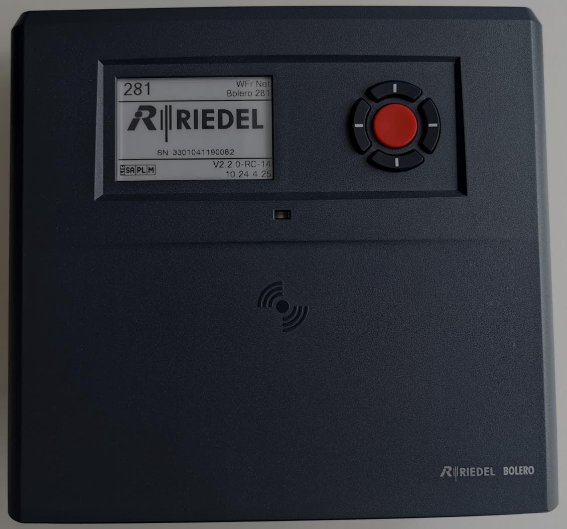
YFJANT100824H
Jul 08, 2024Antenna / Base Station
Equipment Class
DXX - Part 15 Low Power Communication Device Transmitter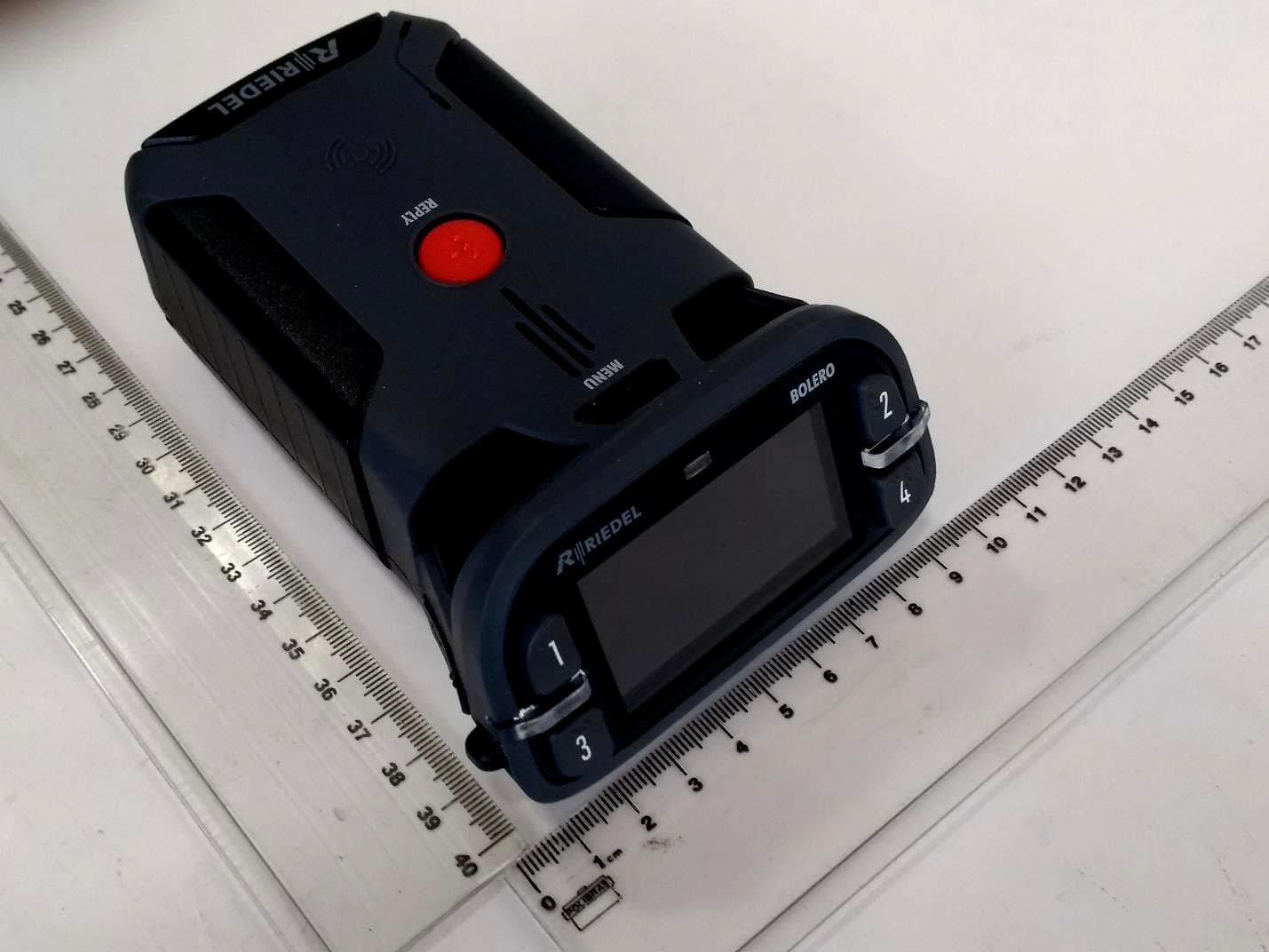
YFJBPK100624H
Jul 08, 2024Beltpack Standard
Equipment Class
DXX - Part 15 Low Power Communication Device Transmitter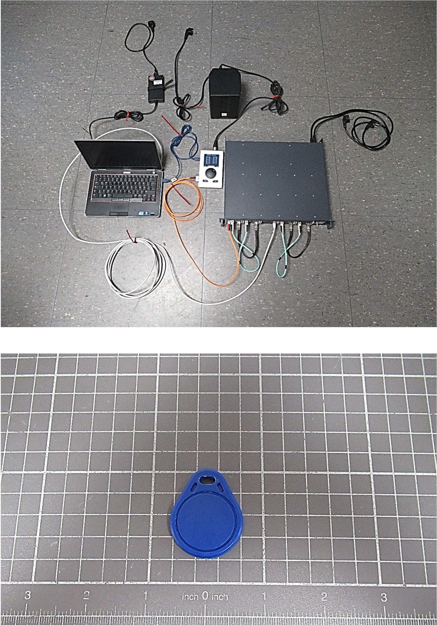
YFJART1024
Dec 11, 2023Modular Intercom Matrix System
Equipment Class
DXX - Part 15 Low Power Communication Device Transmitter
YFJDIS1024
Feb 25, 2021Display unit with integrated RFID reader
Equipment Class
DXX - Part 15 Low Power Communication Device Transmitter