YG32200RUltra Short Range Communication Device (USRCD) with Wireless Power Transfer
Phoenix Contact GmbH & Co. KG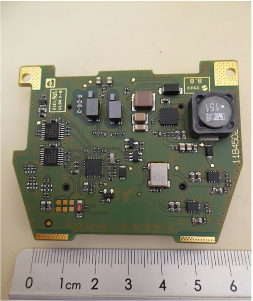
Click to zoom
Application Details
- Equipment Class
- DXX - Part 15 Low Power Communication Device Transmitter
- Date of Grant
- May 03, 2026
- Application Purpose
- Original Equipment
- Equipment Note
- Ultra Short Range Communication Device (USRCD) with Wireless Power Transfer
- Frequency Range
- 57000.00000000 - 71000.00000000
- Country
- Germany
Documents & Files
Document Text
Text extracted from the exhibit documents filed with the FCC. Open a document above to read the original.
Users Manual
User manual NearFi couplers for contactless power and real-time Ethernet data transmission 2026-04-27 Phoenix Contact GmbH & Co. KG • Flachsmarktstraße 8 • 32825 Blomberg • Germany phoenixcontact.com 1 1 0 7 1 8 _ e n _ 0 2 NearFi couplers for contactless power and real-time Ethernet data transmission This user manual is valid for: DesignationItem No. NEARFI2200B1433050 NEARFI2200R1433049 NEARFI200B1433047 NEARFI200R1433046 NEARFI300B1464614 NEARFI300R1509989 NEARFI2000B1433041 NEARFI2000R1433040 User manual UM EN NEARFI, Revision 02 Table of contents 110718_en_02Phoenix Contact3 / 102 Table of contents 1For your safety .............................................................................................................................5 1.1Identification of warning notes...............................................................................5 1.2Qualification of users..............................................................................................5 1.3Field of application of the product..........................................................................6 1.4Safety notes.............................................................................................................6 1.5Protection against tampering..................................................................................7 1.6User documentation................................................................................................8 1.7UL notes...................................................................................................................9 2FCC approval .............................................................................................................................10 2.1Part 15..................................................................................................................10 2.2Part 18..................................................................................................................11 2.3Intended use description for industrial inductive couplers................................11 2.4Installation instructions for applications using Nearfi base units (NEARFI2200B, NEARFI300B, NEARFI200B)...............................................12 2.5Part15, 18............................................................................................................14 3Transport, storage, and unpacking ...........................................................................................15 3.1Transport..............................................................................................................15 3.2Storage..................................................................................................................15 3.3Unpacking.............................................................................................................16 4Product description ...................................................................................................................17 4.1Functional principle..............................................................................................18 4.2Installation examples...........................................................................................19 4.3Compatibility........................................................................................................33 4.4Basic circuit diagram............................................................................................34 4.5Function elements................................................................................................38 4.6DIP switches.........................................................................................................40 4.7Ethernet................................................................................................................43 4.8Switch-on time (operational readiness time)......................................................44 4.9Positioning of the devices....................................................................................45 4.10Obstacles in the air gap........................................................................................49 4.11Foreign objects in the air gap...............................................................................49 4.12Minimum clearances............................................................................................50 4.13Installation in metal.............................................................................................50 NEARFI 4 / 102Phoenix Contact 110718_en_02 4.14Coupling the base and remote couplers..............................................................51 4.15Derating................................................................................................................53 5Installation ................................................................................................................................58 5.1Mounting and removal..........................................................................................58 5.2Connecting cables................................................................................................62 5.3Startup and maintenance.....................................................................................72 6Troubleshooting ........................................................................................................................73 6.1Diagnostic LEDs....................................................................................................73 7Device replacement, device defect and repair .........................................................................80 7.1Device replacement.............................................................................................80 7.2Device defect and repair......................................................................................80 8Maintenance and disposal ......................................…
Text truncated - open the document above for the full version.
Users Manual
NEARFI 76 / 102Phoenix Contact 110718_en_02 LED ring on the remote coupler lights up red Only for the NEARFI200R power coupler Figure6-5Critical error on remote in parallel operation If the remote coupler LED ring lights up red, there is a critical error. Possible reasons: –NEARFI200B not transmitting power to NEARFI200R –Internal temperature too high –Internal error •Check the power supply unit. •Check the connected load on the remote side. •Check the air gap between the devices. •Reduce the distance, the offset, or the angle between the devices if necessary. •Contact PhoenixContact if these measures do not help. 2200 B2200 R 200 B200 R Troubleshooting 110718_en_02Phoenix Contact77 / 102 6.1.3Critical error on the base Only for the NEARFI2200 power and data couplers and the NEARFI200/300 pow- er couplers Figure6-6Critical error If the base coupler LED ring lights up red, there is a critical error. Possible reasons: –Supply voltage outside of the nominal range (19VDC...30VDC) –Internal temperature too high –Internal error To protect the coupler and other devices, the remote coupler switches off. No more power is transmitted. •Check the power supply unit. •Check the connected load on the remote side. •Check the air gap between the devices. •Reduce the distance, the offset, or the angle between the devices if necessary. •Contact PhoenixContact if these measures do not help. a RemoteBase NEARFI 78 / 102Phoenix Contact 110718_en_02 6.1.4Malfunction on the data line Only for the NEARFI2200 power and data couplers and the NEARFI2000 data cou- plers Figure6-7LAN malfunction If a twisted pair segment malfunctions, only the ETH LINK LED of the corresponding port will go out. Fast startup The “Fast startup” function is also referred to as prioritized startup or fast restart. When using network devices with this function, note the following: •Only use routers and switches that support fast startup. •To ensure fast startup of network devices, select “ETH full duplex” operating mode on the NearFi couplers. •Please note that crossover detection is not available in “ETH full duplex” operating mode. The pin assignment of the network connection changes to “Crossover” on the remote coupler. •Select the connecting cable according to the connected device: –Crossover cable with same port assignment –Patch cable with different port assignment a RemoteBase Troubleshooting 110718_en_02Phoenix Contact79 / 102 6.1.5Wireless connection not optimal Only for the NEARFI2000 data couplers Figure6-8Wireless connection not optimal The LED ring on the base and the remote flashes green if the distance or the offset be- tween the couplers is too great. •Check the air gap between the devices. •Reduce the distance, the offset, or the angle between the devices if necessary. a RemoteBase NEARFI 80 / 96Phoenix Contact 110718_en_02 7Device replacement, device defect and repair 7.1Device replacement NOTE:Device damage Only mount and remove devices when the power supply is disconnected. You can replace the device if necessary. •Disconnect the device from the power supply. •Remove all cables. •Remove the device as described in “Mounting and removal” on page58. •Replace the device with an identical device (the same item no.). 7.2Device defect and repair Repairs may only be carried out by PhoenixContact. •Send defective devices back to PhoenixContact for repair or to receive a replace- ment device. •We strongly recommend using the original packaging to return the product. •Include a note in the packaging indicating that the contents are returned goods. •Include an error description with the returned product. •If the original packaging is no longer available, observe the following points: –Observe the humidity specifications and the temperature range specified for transport (see “Ambient conditions” on page91). –Use dehumidifying agents if necessary. –Use suitable ESD packaging to protect components that are sensitive to electro- static discharge. –Make sure that the packaging you select is large enough and sufficiently thick. –Only use plastic bubble wrap sheets as wadding. –Attach warnings to the transport packaging so that they are clearly visible. –Please ensure that the delivery note is placed inside the package if the package is to be shipped domestically. However, if the package is being shipped interna- tionally, the delivery note must be placed inside a delivery note pocket and at- tached to the outside so that it is clearly visible. Device replacement, device defect and repair 110718_en_02Phoenix Contact81 / 96 8Maintenance and disposal 8.1Maintenance The device is maintenance-free. 8.2Disposal The symbol with the crossed-out trash can indicates that this item must be collect- ed and disposed of separately. PhoenixContact or our service partners will take the item back for free disposal. For information on the available disposal options, visit phoenixcontact.com. •Set all DIP switches to “off” before disposal. •Dispose of packaging materials that are no longer needed (cardboard packaging, paper, bubble wrap sheets, etc.) with household waste in accordance with the currently applicable national regulations. NEARFI 82 / 102Phoenix Contact 110718_en_02 9Technical data 9.1Ordering data NEARFITypeItem no.Pcs./Pkt. Power and data coupler, 50W (US), 100Mbps full duplex, M12 push-pull, IP65, optional: 100W (US) in conjunction with NEARFI200 or 2x50W (US+UA) with NEARFI300 Base couplerNEARFI2200B14330501 Remote couplerNEARFI2200R14330491 Power coupler, 50W (UA), M12 push-pull, IP65, optional: 2x50W (US+UA) in conjunction with NEARFI2200/200 Base couplerNEARFI300B14646141 Remote couplerNEARFI300R15099891 Power coupler, 50W (US), M12 push-pull, IP65, optional: 100W (US) in conjunction with NEARFI2200/200 or 2x50W (US+UA) with NEARFI300 Base couplerNEARFI200B14330471 Remote couplerNEARFI200R14330461 Data coupler, 100Mbps full duplex, range up to 10cm, M12 push-pull, IP65 Base couplerNEARFI2000B14330411 Remote couplerNEARFI2000R14330401 …
Text truncated - open the document above for the full version.
Attestation Statements
Covered Equipment Attestation Letter For Certification Service in the USA Federal Communications Commission Equipment Authorization Division, Application Processing Branch 7435 Oakland Mills Road Columbia, MD 21048 To whom it may concern Pursuant to Section 2.911(dX5)(i)-(ii) of the Commission's Rules (47 C.F.R.) we attest as follows for the product listed below: FCC ID I vou"t name YG32200R We, Applicant ;vT J-i:- | rurnnrr 22oo R Phoenix Contact GmbH & Co. KG Flachsmarktstr. 8 D-32825 Blomberg Germany ånZS-,t¿-os Company Name: Address: Phone: +49 5235 300 certify that the equipment for which authorization is sought is not "covered" equipment prohibited from receiving an equipment authorization pursuant to section 2.903 of the FCC rules. This includes the cybersecurity and anti-virus software produced or provided by Kaspersky Lab, lnc.. We certify that, as of the date of the filing of the application, the applicant is not identified on the Covered List as an entity producing "covered" equipment. lf you have any questions, please feel free to contact us at the address shown below. Sincerely, SignaturO tno"n'If8ffi :lSiBBÍru co. KG D-3Z8ZS Btomberg Printed Name of Signee: Dinger Florian Company: Phoenix Contact GmbH & Co. KG Address: Flachsmarktstraße 8 D-32825 Blomberg Phone: +4952353-43748 Fax: +4952353-4t41O E-Mail: [email protected]: Date
Attestation Statements
Local Representative Letter For Certification Service in the USA Federal Communications Commission Equipment Authorization Division, Application Processing Branch 7435 Oakland Mills Road Columbia, MD 21048 To whom it may concern Pursuant to Section 2.9ll(d)(7), of the Commission's Rules (47 C.F R.) we attest as follows for the product listed below: FCCID Model name YG32200R NEARFI 2200 R We hereby acknowledge as follows: i. both signees confirm that the point of contact accepts responsibility to act as a US- American Representative on behalf of the applicant ii. the point of contact provides the physical U.S. address and email as listed below iii. both parties maintain the requirements of this agreement for no less than one year after the grantee has terminated all marketing and importation or the conclusion of any Commission-related proceeding involving the equipment. US-American Point of Contact Applicant/ Approval Holder ";~)JOk¾ IJ/or;/2-s- ,·.v.-:r.J.:&3 loll-0~-l+ Signature Sig ure Company Name: Phoenix Contact USA FRN: 0022526594 Contact Name: Thomas Olsen Address: 586 Fulling Mill Road, Middletown, PA 17057 Phone: +1 717-571-4966 Email: [email protected] Phoenix Contact GmbH & Co. KG 0019879626 Florian Dinger Flachsmarktstrasse 8 32825 Blomberg Germany Phoenix Contact GmbH & Co, KG FlachsmarktstraBe 8 D-32825 Blomberg +49 5235 3-43748 [email protected]
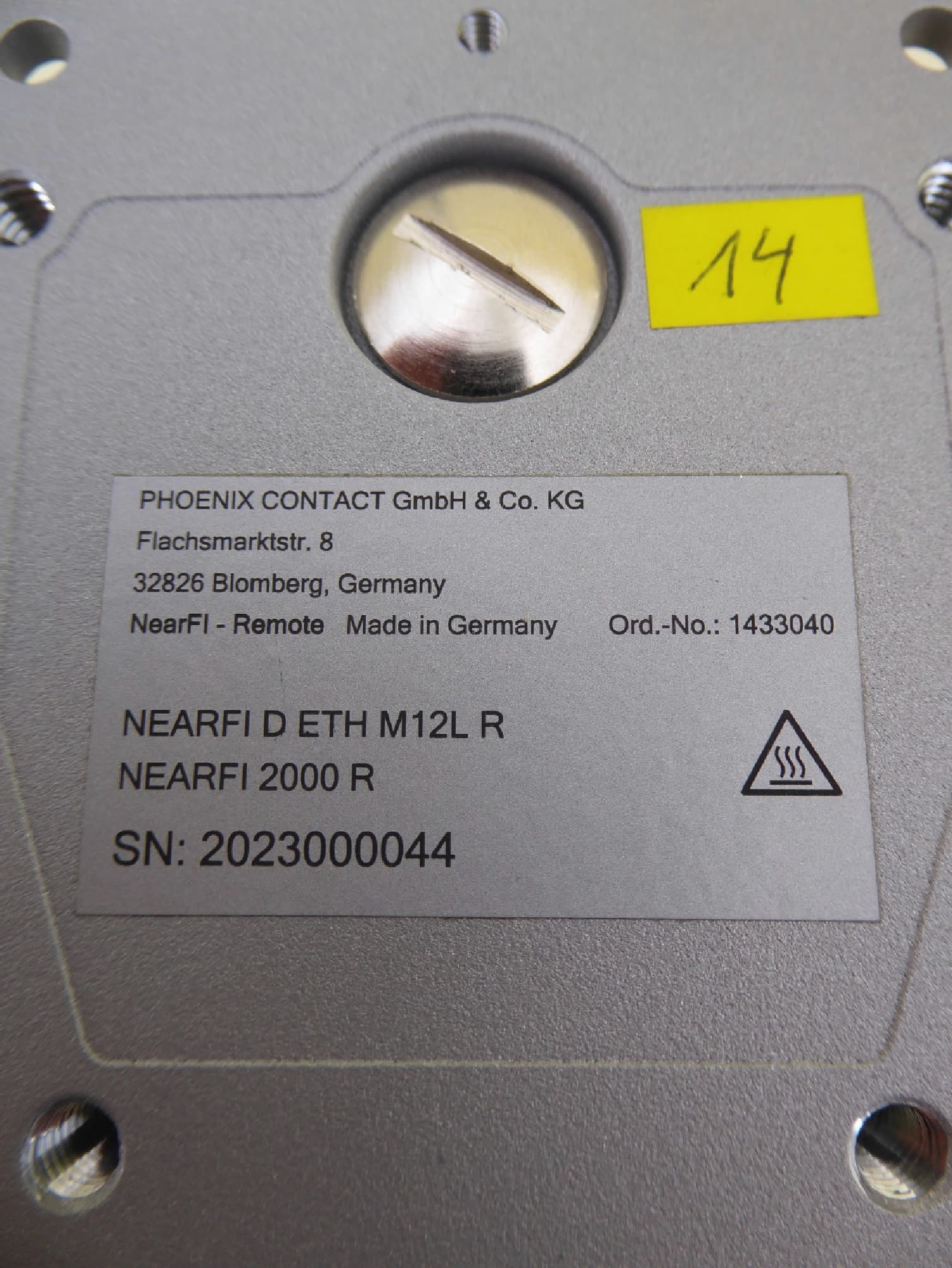
External Photos
Art. No.Article Name 1433049NEARFI 2200 R Photographs 1 Housing 2 Components parts 3 PCBs Radio 60GHz PCB Top Radio 60GHz PCB Bottom Data PCB Top Data PCB Bottom Energy PCB Top Energy PCB Bottom Interface PCB Top Interface PCB Bottom
ID Label/Location Info
Art. No.Article Name 1433049 NEARFI 2200 R Label and Label-Location 1 Label 2 Location
Internal Photos
Art. No.Article Name 1433049NEARFI 2200 R Photographs 1 Housing 2 Components parts 3 PCBs Radio 60GHz PCB Top Radio 60GHz PCB Bottom Data PCB Top Data PCB Bottom Energy PCB Top Energy PCB Bottom Interface PCB Top Interface PCB Bottom
RF Exposure Info
Company: IBL-Lab GmbH · Heinrich-Hertz-Allee 7 · 66386 St. Ingbert · Germany · Tel: +49 6894 38938-0 · Fax: +49 6894 38938-99 1 / 38 Company Register: 105151, Amtsgericht Saarbrücken URL: ib-lenhardt.com · E-Mail: [email protected] Test Report Test report no.: 25011068-44168-0 Date of issue: 2025-08-25 Test result: The test item - passed - and complies with the listed standards. Applicant Phoenix Contact GmbH & Co. KG Manufacturer Phoenix Contact GmbH Test Item NEARFI 2200 B / NEARFI 2200 R Radio Frequency Testing according to: FCC 47 CFR Part 15 Radio frequency devices Parts 1.1307, 1.1310, 2.1091, 2.1093 680106 D01 RF Exposure Wireless Charging Apps v04 Tested by (name, function, signature) Andreas Bender Deputy Managing Director Approved by (name, function, signature) Sebastian Janoschka Head of Department RF {{$tested}} {{$approved}} Sebastian Janoschka (Aug 29, 2025 11:22:43 GMT+2) TR no.: 25011068-44168-0 2025-08-25 2 / 38 IBL-Lab GmbH Applicant and Test item details Applicant Phoenix Contact GmbH & Co. KG Dringenauer Straße 30, 31812 , Bad Pyrmont , Germany Name for contact purposes: Maik STEMME Fon: +49 5281 946 3381 eMail address: [email protected] Manufacturer Phoenix Contact GmbH & Co. KG Flachsmarktstr. 8, 32825 , Blomberg , Germany Name for contact purposes: Maik STEMME Fon: +49 5281 946 3381 eMail address: [email protected] Test item description NEARFI energy and data coupler (Base) Model/Type reference (unique) NEARFI 2200 B / NEARFI 2200 R Standard specific information Frequency 110-148 kHz, 63.2625 GHz, 59.850 GHz, 10 MHz Technology WPT, Datalink, Datalink, Feedback CH Antenna PCB antenna Power supply 19 ~ 30 Vdc, 24 Vdc nominal, 50 W Temperature range -20 ~ +55°c FCC ID YG32200B / YG32200R {{#tested=Sig_es_:signer1:signature:align(center):dimension(width=35mm, height=15mm)}} {{#approved=Sig_es_:signer2:signature:align(center):dimension(width=35mm, height=15mm)}} Disclaimer and Notes The content of this report relates to the mentioned test sample(s) only. IBL-Lab GmbH does not take samples. The samples used for testing are provided by the applicant. Without a written permit of IBL-Lab GmbH, this test report shall not be reproduced, except in full. The last valid version is available at TAMSys . Signatures are done electronically, if signer does not match stated signer, it is signed per order. Information supplied by the applicant can affect the validity of results. The data is marked accordingly. Copyright ©: All rights reserved by IBL-Lab GmbH Within this test report, a ☒ point / ☐ comma is used as a decimal separator. If otherwise, a detailed note is added adjected to its use. Decision rule: Decision rule based on simple acceptance without guard bands, binary statement, based on mutually agreed uncertainty tolerances with expansion factor k=2. TR no.: 25011068-44168-0 2025-08-25 3 / 38 IBL-Lab GmbH 1 TABLE OF CONTENTS 1 TABLE OF CONTENTS ......................................................................................................................... 3 2 GENERAL INFORMATION ................................................................................................................... 4 2.1 Administrative details .......................................................................................................................... 4 2.2 Possible test case verdicts ................................................................................................................. 5 2.3 Observations ....................................................................................................................................... 5 2.4 Opinions and interpretations ............................................................................................................... 5 2.5 Document history ................................................................................................................................ 5 3 ENVIRONMENTAL CONDITIONS ........................................................................................................ 6 3.1 Environmental conditions of lab .......................................................................................................... 6 4 TEST STANDARDS AND REFERENCES ............................................................................................ 6 5 MPE Assessment Requirements ........................................................................................................... 7 5.1 FCC – KDB 680106 D01 RF Exposure Wireless Charging Apps v04 ............................................... 7 5.1.1 Limits – 3.2 Equipment Authorization Procedures for Devices Operating at Frequencies Below 4 MHz 7 5.1.2 5.2 Part 18 Wireless Power Transfer up to One-Meter Distance ........................................................ 8 5.1.3 EUT setup + Measurements .............................................................................................................. 10 5.2 Simultaneous transmission MPE ...................................................................................................... 16 6 List of test equipment used .................................................................................................................. 18 Annex 1 Photo Documentation .......................................................................................................................... 19 Annex 2 System Performance Check 85 kHz .................................................................................................... 27 Annex 3 Measurement Plots for WPT ................................................................................................................ 29 TR no.: 25011068-44168-0 2025-08-25 4 / 38 IBL-Lab GmbH 2 GENERAL INFORMATION 2.1 Administrative details Testing laboratory IBL-Lab GmbH Heinrich-Hertz-Allee 7 66386 St. Ingbert / Germany Fon: +49 6894 38938-0 Fax: +49 6894 38938-99 URL: https://ib-lenhardt.com/ E-Mail: info@ib…
Text truncated - open the document above for the full version.
Test Report
Annex A Measurement results Test engineer: Thomas KÜHNReport Number: F231978E3 Date of issue: 05.11.2024Order Number:23-111978page 1 of 8 A.1 Operating bandwidth 231978_103.png: Operating bandwidth (-6dB): A.2 99 % bandwidth 231978_102.png: 99 % bandwidth: Annex A Measurement results Test engineer: Thomas KÜHNReport Number: F231978E3 Date of issue: 05.11.2024Order Number:23-111978page 2 of 8 A.3 Fundamental emission (eirp) 231978_107.png: Peak transmission power / peak power density inside the 57 to 71 GHz band: 231978_106.png: Average power: Annex A Measurement results Test engineer: Thomas KÜHNReport Number: F231978E3 Date of issue: 05.11.2024Order Number:23-111978page 3 of 8 A.4 Unwanted emissions Spurious emissions from 9 kHz to 30 MHz: Measured in 3 m distance (calculated to the normative distance with 40 dB/decade according to 15.31 (f)(2)) Spurious emissions from 30 MHz to 1 GHz: Annex A Measurement results Test engineer: Thomas KÜHNReport Number: F231978E3 Date of issue: 05.11.2024Order Number:23-111978page 4 of 8 Spurious emissions from 1 GHz to 12 GHz: Spurious emissions from 12 GHz to 18 GHz: 0 20 40 60 80 100 1 2 3 4 5 678 9 10 11 12 Level in dBμV/m Frequency in GHz P review Result 1-P K+§15.209 & RSS-GEN 1-40 GHz P k 3m co nt. §15.209 & RSS-GEN 1-40 GHz A V 3m co nt. §15.209 & RSS-GEN 1-40 GHz P k 3m co nt. §15.209 & RSS-GEN 1-40 GHz A V 3m co nt. 0 10 20 30 40 50 60 70 80 12131415161718 Lev el in dBμV/m Frequency in GHz P review Result 1-P K+§15.209 & RSS-GEN 1-40 GHz P k 3m co nt. §15.209 & RSS-GEN 1-40 GHz A V 3m co nt. §15.209 & RSS-GEN 1-40 GHz P k 3m co nt. §15.209 & RSS-GEN 1-40 GHz A V 3m co nt. Annex A Measurement results Test engineer: Thomas KÜHNReport Number: F231978E3 Date of issue: 05.11.2024Order Number:23-111978page 5 of 8 Spurious emissions from 18 GHz to 26.5 GHz: Spurious emissions from 26.5 GHz to 40 GHz: 0 10 20 30 40 50 60 70 80 18192021222324252626.5 Level in dBμV/m Frequency in GHz P review Result 1-P K+§15.209 & RSS-GEN 1-40 GHz P k 3m co nt. §15.209 & RSS-GEN 1-40 GHz A V 3m co nt. §15.209 & RSS-GEN 1-40 GHz P k 3m co nt. §15.209 & RSS-GEN 1-40 GHz A V 3m co nt. 10 20 30 40 50 60 70 80 90 26.528303234363840 Level in dBμV/m Frequency in GHz P review Result 1-P K+ Annex A Measurement results Test engineer: Thomas KÜHNReport Number: F231978E3 Date of issue: 05.11.2024Order Number:23-111978page 6 of 8 231978_113.png: Spurious emissions from 40 GHz to 50 GHz: 231978_109.png: Spurious emissions from 50 GHz to 75 GHz: Annex A Measurement results Test engineer: Thomas KÜHNReport Number: F231978E3 Date of issue: 05.11.2024Order Number:23-111978page 7 of 8 231978_110.png: Spurious emissions from 75 GHz to 110 GHz: 231978_111.png: Spurious emissions from 110 GHz to 170 GHz: Annex A Measurement results Test engineer: Thomas KÜHNReport Number: F231978E3 Date of issue: 05.11.2024Order Number:23-111978page 8 of 8 231978_112.png: Spurious emissions from 170 GHz to 200 GHz: A.5 Conducted emissions on power supply line Conducted emissions on power supply line: ----- end of annex ----- 0 20 40 60 80 150k300 400 500 800 1M2M3M4M 5M 6 8 10M20M30M Lev el in dBμV Frequency in Hz P review Result 2-A VGP review Result 1-P K+FCC 15.207 V QP FCC 15.207 V A V Final_Result QP KFinal_Result A VG
Test Report
Königswinkel 10 32825 Blomberg, Germany Phone: +49 (0) 52 35 / 95 00-0 Fax: +49 (0) 52 35 / 95 00-10 [email protected] www.phoenix-testlab.de Test Report Report Number: F231978E3 Equipment under Test (EUT): NEARFI 2200 R Applicant: PHOENIX CONTACT Electronics GmbH Manufacturer: PHOENIX CONTACT GmbH & Co.KG Examiner: Thomas KÜHN Report Number: F231978E3 Date of Issue: 05.11.2024 Order Number: 23-111978 Page 2 of 33 References [1] ANSI C63.10-2020, American National Standard of Procedures for Compliance Testing of Unlicensed Wireless Devices [2] FCC CFR 47 Part 15, Radio Frequency Devices [3] RSS-210 Issue 10 December 2019, Licence-Exempt Radio Apparatus: Category I Equipment [4] RSS-Gen Issue 5 February 2021 Amendment 2, General Requirements for Compliance of Radio Apparatus Test Result The requirements of the tests performed as shown in the overview (clause 4) were fulfilled by the equipment under test. The complete test results are presented in the following. “Passed” indicates that the equipment under test conforms with the relevant limits of the testing standard without taking any measurement uncertainty into account as stated in clause 1.4 of ANSI C63.10 (2020). However, the measurement uncertainty is calculated and shown in this test report. Tested: o.b.o. Signature Tested and written by: Signature Reviewed and approved by: Signature T h i s t e s t r e p o r t i s o n l y v a l i d i n i t s o r i g i n a l f o r m. Any reproduction of its contents in extracts without written permission of the accredited test laboratory PHOENIX TESTLAB GmbH is prohibited. The test results herein refer only to the tested sample. PHOENIX TESTLAB GmbH is not responsible for any generalisations or conclusions drawn from these test results concerning further samples. Any modification of the tested samples is prohibited and leads to the invalidity of this test report. Each page necessarily contains the PHOENIX TESTLAB Logo and the TEST REPORT NUMBER. Examiner: Thomas KÜHN Report Number: F231978E3 Date of Issue: 05.11.2024 Order Number: 23-111978 Page 3 of 33 Contents: Page 1.1 Applicant ................................................................................................................................................... 5 1.2 Manufacturer ............................................................................................................................................ 5 1.3 Test Laboratory ........................................................................................................................................ 5 1.4 EUT (Equipment under Test) ................................................................................................................... 6 1.5 Technical Data of Equipment ................................................................................................................... 6 1.6 Dates ........................................................................................................................................................ 7 5.1 Test setups ............................................................................................................................................... 9 5.1.1 Radiated: 9 kHz to 30 MHz .............................................................................................................. 9 5.1.1.1 Preliminary measurement 9 kHz to 30 MHz ........................................................................... 9 5.1.1.2 Final measurement 9 kHz to 30 MHz ................................................................................... 10 5.1.2 Radiated: 30 MHz to 1 GHz ........................................................................................................... 11 5.1.2.1 Preliminary and final measurement 30 MHz to 1 GHz ......................................................... 11 5.1.3 Radiated: 1 GHz to 40 GHz ........................................................................................................... 13 5.1.3.1 Preliminary and final measurement 1 GHz to 40 GHz .......................................................... 13 5.1.4 Radiated: 40 GHz to 200 GHz ....................................................................................................... 15 5.1.4.1 Preliminary and final measurement 40 GHz to 200 GHz ...................................................... 15 5.1.5 Frequency stability ......................................................................................................................... 17 5.1.5.1 Method of measurement (frequency stability)....................................................................... 17 5.1.6 Conducted emission: AC power line ............................................................................................. 18 5.2 Fundamental emissions bandwidth ........................................................................................................ 19 5.2.1 Test setup (Fundamental emission bandwidth) ............................................................................. 19 5.2.2 Test method (-6 dB bandwidth) ..................................................................................................... 19 5.2.3 Test method (99 % bandwidth) ...................................................................................................... 19 5.2.4 Test results (fundamental emission ban…
Text truncated - open the document above for the full version.
Contact Information
Applicant
Dinger Florian(Director Product Compliance)
[email protected]Fax: +495235312999
Test Firm
PHOENIX TESTLAB GmbHHolger Bentje
[email protected]Fax: 49-5235-9500-28
Technical Specifications
| # | Rule Parts | Frequency Range | Power Output |
|---|---|---|---|
| 1 | 15C | 57.00 GHz - 71.00 GHz | 3.00 mW |
Other Applications from Phoenix Contact GmbH & Co. KG
YG32000R
May 03, 2026Ultra Short Range Communication Device (USRD)
Equipment Class
DXX - Part 15 Low Power Communication Device Transmitter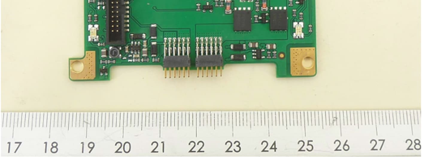
YG3300R
May 03, 2026Wireless Power Transfer
Equipment Class
JAB - Part 15 Class B Digital Device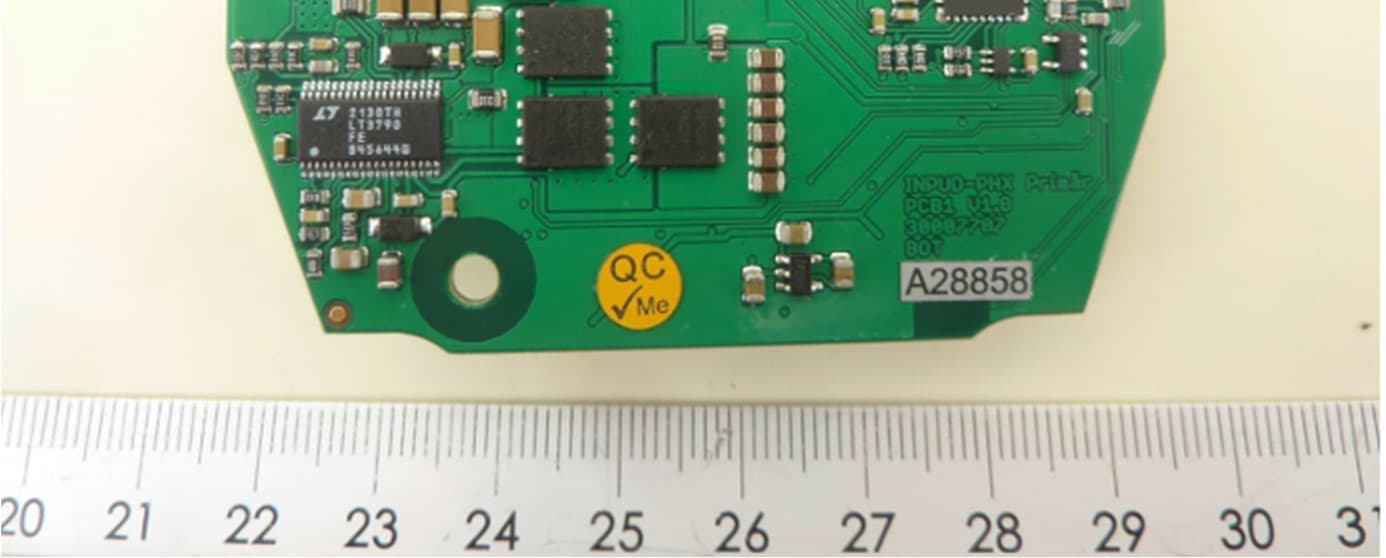
YG3300B
May 03, 2026Wireless Power Transfer
Equipment Class
8CC - Part 18 Consumer Device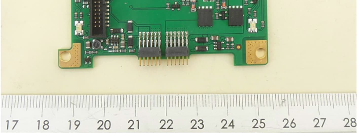
YG3200R
May 03, 2026Wireless Power Transfer
Equipment Class
JAB - Part 15 Class B Digital Device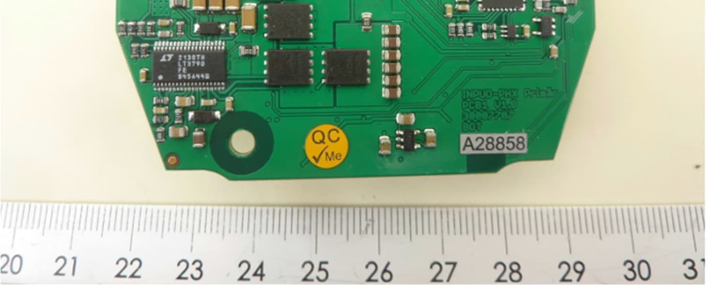
YG3200B
May 03, 2026Wireless Power Transfer
Equipment Class
8CC - Part 18 Consumer Device