YG3P2AREnergy Coupler Remote
Phoenix Contact GmbH & Co. KG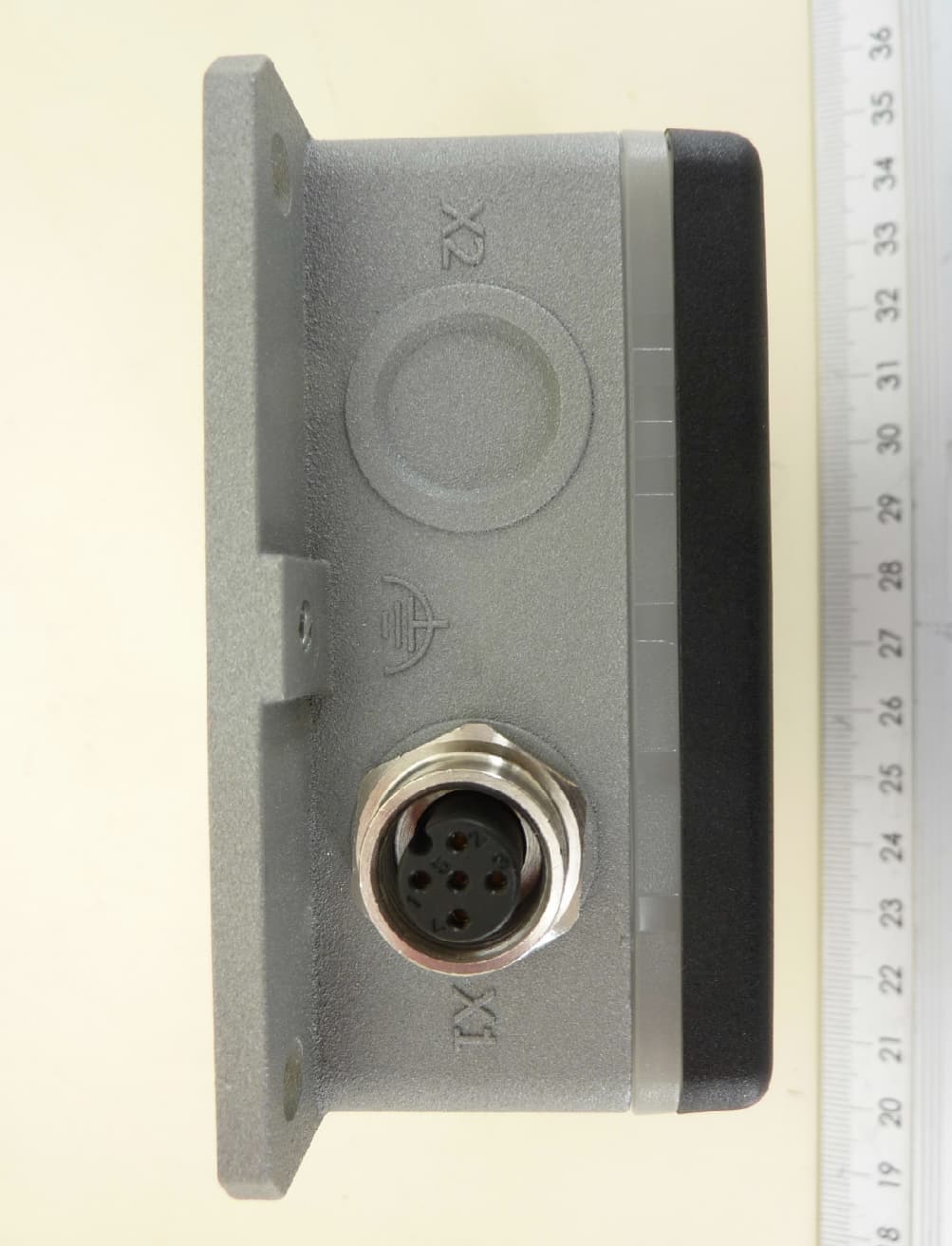
Click to zoom
Application Details
- Equipment Class
- DXX - Part 15 Low Power Communication Device Transmitter
- Date of Grant
- Aug 05, 2024
- Application Purpose
- Original Equipment
- Date of Application
- Aug 05, 2024
- Equipment Note
- Energy Coupler Remote
- Frequency Range
- 10.00000000 - 10.00000000
- Country
- Germany
Documents & Files
Document Text
Text extracted from the exhibit documents filed with the FCC. Open a document above to read the original.
Users Manual
1 Description NearFi coupler for contactless power and data transmission NEARFI... © Phoenix Contact Data sheet The NearFi coupler transmits power and real-time Ether- net data contactlessly over an air gap in the centimeter range. For contactless transmission, you will need at least two devices: a base and one or more remote couplers. The base coupler transmits the energy inductively to the remote coupler. Ethernet transmission is bidirectional between the base and the remote. In maintenance-intensive applications, such as tool changes on robots, this enables wear-prone connections to be replaced easily and minimizes downtime costs. The base and remote couplers are both available in three versions: –Power and data transmission (NEARFI PD...) –Only power transmission (NEARFI P...) –Only data transmission (NEARFI D...) Features –Contactless - and therefore no wear and no mainte- nance –Protocol-independent, latency-free Ethernet real- time communication with 100 Mbps (full duplex) –High power in a compact housing –All-round visible diagnostics with light ring on the housing –High degree of mounting freedom with flexible prox- imity options –Plug and Play - as easy as a plug –Degree of protection IP65 –Protocol-transparent transmission of all standard Ethernet protocols Observe this note Make sure you always use the latest documentation. It can be downloaded at: phoenixcontact.com/product/1234224 This document is valid for the products listed in the “Ordering data” chapter. 109708_en_04 2024-07-25 NEARFI... 109708_en_04Phoenix Contact2 / 39 2 Table of contents 1Description.................................................................................................................................1 2Table of contents.......................................................................................................................2 3Ordering data.............................................................................................................................3 4Technical data............................................................................................................................7 5Safety regulations and installation notes...............................................................................13 6Functional principle................................................................................................................19 7Transport and unpacking........................................................................................................20 8Product description.................................................................................................................20 9Installation..............................................................................................................................26 10Connecting the cables.............................................................................................................31 11Maintenance and disposal......................................................................................................33 12Troubleshooting......................................................................................................................34 13Derating...................................................................................................................................37 NEARFI... 109708_en_04Phoenix Contact3 / 39 DescriptionTypeItem no.Pcs./Pkt. NearFi, base coupler for contactless power and real- time Ethernet transmission in the centimeter range, 24 V DC, 2 A, 100 Mbps, full duplex, M12 connection technology, IP65 type of protection. A remote coupler is required for operation. NEARFI PD 2A ETH B12342241 NearFi, remote coupler for contactless power and real- time Ethernet transmission in the centimeter range, 24 V DC, 2 A, 100 Mbps, full duplex, M12 connection technology, IP65 type of protection. A base coupler is re- quired for operation. NEARFI PD 2A ETH R12342251 NearFi, base coupler for contactless power transmission in the centimeter range, 24 V DC, 2 A, M12 connection technology, IP65 type of protection. A remote coupler is required for operation. NEARFI P 2A B12342261 NearFi, remote coupler for contactless power transmis- sion in the centimeter range, 24 V DC, 2 A, M12 connec- tion technology, IP65 type of protection. A base coupler is required for operation. NEARFI P 2A R12342291 NearFi, base coupler for contactless real-time Ethernet transmission in the centimeter range, 100 Mbps, full du- plex, M12 connection technology, IP65 type of protec- tion. A remote coupler is required for operation. NEARFI D ETH B12342321 NearFi, remote coupler for contactless real-time Ether- net transmission in the centimeter range, 100 Mbps, full duplex, M12 connection technology, IP65 type of pro- tection. A base coupler is required for operation. NEARFI D ETH R12342341 3 Ordering data AccessoriesTypeItem no.Pcs./Pkt. Sensor/actuator cable, 5-position, PUR, black-gray RAL 7021, free cable end, on Socket straight M12 SPEEDCON, coding: A, cable length: 2 m SAC-5P- 2,0-186/FS SCO15183681 Sensor/actuator cable, 5-position, PUR, black-gray RAL 7021, free cable end, on Socket straight M12 SPEEDCON, coding: A, cable length: 5 m SAC-5P- 5,0-186/FS SCO15183711 Sensor/actuator cable, 5-position, PUR, black-gray RAL 7021, free cable end, on Socket straight M12 SPEEDCON, coding: A, cable length: 10 m SAC-5P-10,0-186/FS SCO15183841 Sensor/actuator cable, 5-position, PUR, black-gray RAL 7021, free cable end, on Socket straight M12 SPEEDCON, coding: A, cable length: 15 m SAC-5P-15,0-186/FS SCO15183971 Sensor/actuator cable, 5-position, PUR, black-gray RAL 7021, Plug straight M12 SPEEDCON, coding: A, on Socket straight M12 SPEEDCON, coding: A, cable length: 1 m SAC-5P-MS/ 1,0-186/FS SCO15184231 NEARFI... 109708_en_04Phoenix Contact4 / 39 Sensor/actuator cable, 5-position, PUR, black-gray RAL 7021, Plug straight M12 SPEEDCON, coding: A, on Socket straight M12 SPEEDCON, coding: A, …
Text truncated - open the document above for the full version.
Users Manual
Phoenix Contact GmbH & Co. KG Flachsmarktstraße 8, 32825 Blomberg, Germany Fax +49-(0)5235-341200, Phone +49-(0)5235-300 phoenixcontact.com DE Einbauanweisung für die Elektrofachkraft EN Installation notes for electrically skilled persons FR Instructions d'installation pour l'électricien qualifié 2022-10-11 © Phoenix Contact 2022 Induktive Koppler 1 Sicherheitshinweise •Die Installation, Bedienung und Wartung ist von elektrotechnisch qualifiziertem Fachpersonal durchzufüh- ren. Befolgen Sie die beschriebenen Installationsanweisungen. •Halten Sie die für das Errichten und Betreiben geltenden Bestimmungen und Sicherheitsvorschriften (auch nationale Sicherheitsvorschriften) sowie die allgemein anerkannten Regeln der Technik ein. •Beachten Sie die Sicherheitsinformationen, Bedingungen und Einsatzgrenzen in der Produktdokumentati- on. Halten Sie diese ein. •Die Montage und elektrische Installation muss dem Stand der Technik entsprechen. •Öffnen oder Verändern des Geräts ist nicht zulässig. Reparieren Sie das Gerät nicht selbst, sondern erset- zen Sie es durch ein gleichwertiges Gerät. Reparaturen darf nur der Hersteller vornehmen. Der Hersteller haftet nicht für Schäden aus Zuwiderhandlung. Installation •Das Gerät ist ausschließlich für den Betrieb mit Sicherheitskleinspannung (SELV/PELV) einer "Elektrischen Energiequelle" der Klasse ES1 nach EN/IEC 62368-1 und VDE 0868-1 ausgelegt. Das Gerät darf nur an Geräte angeschlossen werden, die die Bedingungen der Klasse ES1 nach EN/IEC 62368-1 erfüllen. •Dimensionieren und sichern Sie die primär- und sekundärseitige Verdrahtung ausreichend. •Beachten Sie die Spannungsverluste auf der Leitung. Die Geräte können bei Unterspannung nicht mehr funktionieren. •Die Anschlussparameter wie z. B. die erforderlichen Abisolierlängen für die Verdrahtung entnehmen Sie den Installationshinweisen zum jeweiligen feldseitigen Rundsteckverbinder. •Die Parallelschaltung von mehreren Remote-Kopplern ist nicht zulässig. Einsatzort •Das Druckgussgehäuse und die geräteseitigen Rundsteckverbinder erfüllen die Schutzart IP65. •Verschließen Sie ungenutzte Anschlussbuchsen mit Schutzkappen, um die Schutzart IP65 sicherzustellen. •Legen Sie den Einsatzort so aus, dass die Verlustwärme abgeleitet werden kann. Montieren Sie das Druck- gussgehäuse an eine Metallplatte, Kühlkörper oder ähnliches wärmeleitendes Material. •Durch Induktionseffekte an den Energiespulen kann sich das Gerät erhitzen. Halten Sie einen Mindest- abstand zu metallischen Gegenständen von 5 mm ein. In einem Abstand von 300 mm werden die Grenzwerte für die elektrische und magnetische Feldstärke erfüllt. Basierend auf der EU-Ratsempfehlung 1999/519/EG gilt dieser Abstand nach EN 62311 als Basisgrenzwert oder Referenzwert für die Sicherheit von Personen in elektromagnetischen Feldern. Für Personen mit aktiven Körperhilfsmitteln (wie z. B. Herzschrittmacher) gelten unter Umständen weitere (betriebliche) Grenzwerte. 2 Kurzbeschreibung () Die NEARFI-P-Koppler übertragen kontaktlos Energie über einen Luftspalt im Zentimeterbereich (24 V DC, 2 A). Der Base-Koppler überträgt die Energie zum Remote-Koppler. 2.1 LED-Ring Befolgen Sie diese Anweisungen für einen sicheren und ordnungsgemäßen Gebrauch. Bewahren Sie die Anweisungen zum späteren Nachschlagen auf. Weitere Informationen finden Sie im zugehörigen Datenblatt unter phoenixcontact.net/products. VORSICHT: Heiße Oberfläche Das Gehäuse der Geräte kann heiß werden. Nach dem Abschalten der Versorgungsspannung kann das Gerät weiterhin heiß sein. – Stellen Sie ausreichenden Berührschutz sicher. – Verhindern Sie unbeabsichtigtes Berühren durch mechanische Absperrung oder durch gut sichtbare Warnhinweise. – Wählen Sie den Einsatzort so, dass keine metallischen Gegenstände in den Luftspalt zwischen Base und Remote gelangen können. WARNUNG: Elektromagnetische Felder Bei Montage und Betrieb entstehen um das Gerät herum elektromagnetische Felder. – Halten Sie mindestens 300 mm Abstand von den Geräten. 1Druckgussgehäuse 2LED-Ring 3Gehäuseoberteil (Energiespule mittig zentriert hinter dem Logo) 4Befestigungsmöglichkeit mit Innengewinde (2x M6, Tiefe = 7 mm) 5Gehäuseunterseite: DIP-Schalter, QR-Code, weitere Befestigungsmöglichkeiten mit Innengewinde (4x M6, Tiefe = 7 mm) 6Befestigungsflansch mit Montagelöchern (Ø = 5,5 mm) 7M12-Rundsteckverbinder für Eingangsspannung (Base-Koppler) oder Ausgangsspannung (Remote- Koppler) 8Funktionserdanschluss mit Innengewinde (1x M4, Tiefe = 5 mm) LED-RingStatusBaseRemote GrünEinBase und Remote gekoppelt, Übertragung aktiv BlinktGerät betriebsbereit, keine Übertra- gung, Luftspalt/Versatz zu groß - Remote-Spannungsausgang Über- last/Kurzschluss AusBase nicht betriebsbereit oder aus- geschaltet über Steuereingang (DI PWR_CTRL) Remote nicht gekoppelt RotEinKritischer Fehler, interne Temperatur zu hoch, externe Versorgungsspan- nung gravierend außerhalb des Nennbereichs - Coupleur inductif 1 Consignes de sécurité •L’installation, l’utilisation et la maintenance doivent être confiées à un personnel spécialisé dûment qualifié en électrotechnique. Respecter les instructions d'installation. •Lors de la mise en place et de l'utilisation, respectez les dispositions et les consignes de sécurité en vigueur (normes de sécurité nationales comprises) ainsi que les règles relatives à la technique généralement recon- nues. •Observez les informations relatives à la sécurité, les conditions et limites d'utilisation comprises dans la documentation du produit. Respectez-les. •Le montage et l'installation électrique doivent correspondre à l'état de la technique. •Il est interdit d'ouvrir et de modifier l'appareil. L'appareil ne peut être réparé par vos soins, mais il peut être remplacé par un appareil équivalent. Seul le fabricant est autorisé à effectuer des réparations. Le fabricant ne peut être tenu pour responsable des dommages résultant d'infractions à ces consignes. Installation •L'appareil est conçu pour être utilisé exclusivement avec une très basse tension…
Text truncated - open the document above for the full version.
Attestation Statements
Phoenix Contact GmbH & Co.KG Flachsmarktstr. 8 D-32825 Blomberg Germany Federal Communication Commission Authorization and Evaluation Division 7435 Oakland Mills Road Columbia, MD 2L046 USA March 30,2023 Attestation Statement according to 2.911(dX5)(i) and 2.911(dX5X¡¡) FCC lD: YG3P2AR TO WHOM IT MAY CONCERN: Hereby we certify that the equipment for which authorization is sought is not "covered" equipment prohibited from receiving an equipment authorization pursuant to section 2.903 of the FCC rules. Further we certify that, as of the date of the filing of the application, Phoenix Contact GmbH & Co.KG is not identified on the Covered List as an entity producing "covered" equipment. Sincqrely, PHOENIX CONTACT GmbH & Cq, K6 Flachsmarl<tstr. B D-32825 Biomberg 1,1\r t" V. l- (signature & company stamp) Name / title: Dinger Florian Company: Phoenix Contact GmbH & Co. KG Address: Flachsmarktstraße 8 D-32825 Blomberg Phone: +4952353-43748 Fax: +4952353-4L410 E-Mail: fdí[email protected] //4
External Photos
External photos of NERFI P 2A R Examiner:Wolfgang KASALOWSKYRevision: 0 Date of issue: 02.06.2023Order Number: 22-110996page 1 of 4 3-D-view 1 of NEARFI P 2A R External photos of NERFI P 2A R Examiner:Wolfgang KASALOWSKYRevision: 0 Date of issue: 02.06.2023Order Number: 22-110996page 2 of 4 3-D-view 2 of NEARFI P 2A R External photos of NERFI P 2A R Examiner:Wolfgang KASALOWSKYRevision: 0 Date of issue: 02.06.2023Order Number: 22-110996page 3 of 4 Typeplate view of NEARFI P 2A R External photos of NERFI P 2A R Examiner:Wolfgang KASALOWSKYRevision: 0 Date of issue: 02.06.2023Order Number: 22-110996page 4 of 4 Connector view of NEARFI P 2A R
ID Label/Location Info
12
Internal Photos
PHOENIX CONTACT GmbH & Co. KG • Flachsmarktstraße 8 • 32825 Blomberg • Germany1/3 Phone: +49-(0) 5235-3-00 • Fax: +49-(0) 5235-3-4 12 00 • www.phoenixcontact.com 1Internal photos transmitter parts NEARFI P_2A_R 1.1Part for Power transfer feedback 10MHz Energy top RF section of 10 MHz transmitter. PHOENIX CONTACT GmbH & Co. KG • Flachsmarktstraße 8 • 32825 Blomberg • Germany2/3 Phone: +49-(0) 5235-3-00 • Fax: +49-(0) 5235-3-4 12 00 • www.phoenixcontact.com PCB Base bottom RF section of 10 MHz transmitter. PHOENIX CONTACT GmbH & Co. KG • Flachsmarktstraße 8 • 32825 Blomberg • Germany3/3 Phone: +49-(0) 5235-3-00 • Fax: +49-(0) 5235-3-4 12 00 • www.phoenixcontact.com Lid with potting Antenna of 10 MHz transmitter.
Internal Photos
Internal photos of NERFI P 2A R Examiner:Wolfgang KASALOWSKYRevision : 0 Date of issue: 02.06.2023Order Number: 22-110998page 1 of 5 EUT (Base) – Cabinet opened Internal photos of NERFI P 2A R Examiner:Wolfgang KASALOWSKYRevision : 0 Date of issue: 02.06.2023Order Number: 22-110998page 2 of 5 EUT (Base) – Cabinet opened Internal photos of NERFI P 2A R Examiner:Wolfgang KASALOWSKYRevision : 0 Date of issue: 02.06.2023Order Number: 22-110998page 3 of 5 EUT (Base) – Data PCB Internal photos of NERFI P 2A R Examiner:Wolfgang KASALOWSKYRevision : 0 Date of issue: 02.06.2023Order Number: 22-110998page 4 of 5 EUT (Base) – Energy PCB Internal photos of NERFI P 2A R Examiner:Wolfgang KASALOWSKYRevision : 0 Date of issue: 02.06.2023Order Number: 22-110998page 5 of 5 EUT (Base) – Interface PCB
RF Exposure Info
Königswinkel 10 32825 Blomberg, Germany Phone: +49 (0) 52 35 / 95 00-0 Fax: +49 (0) 52 35 / 95 00-10 [email protected] www.phoenix-testlab.de Test Report Report Number: F220998E3 Equipment under Test (EUT): NEARFI P 2A R Applicant: PHOENIX CONTACT Electronics GmbH Manufacturer: PHOENIX CONTACT GmbH & Co.KG Examiner: Thomas KÜHN Report Number: F220998E3 Date of Issue: 01.08.2024 Order Number: 22-110998 Page 2 of 18 References [1] CFR 47 Rule part 1 Practice and Procedure [2] CFR 47 Rule part 2 Frequency Allocations and Radio Treaty Matters; General Rules and Regulations [3] KDB 447498 D04 Interim General RF Exposure Guidance v01 [4] KDB 680106 D01 Wireless Power Transfer v04 Test Result The requirements of the tests performed as shown in the results (clause 3) were fulfilled by the equipment under test. The complete test results are presented in the following. “Passed” indicates that the equipment under test conforms with the relevant limits of the testing standard without taking any measurement uncertainty into account. However, the measurement uncertainty is calculated and shown in this test report. T h i s t e s t r e p o r t i s o n l y v a l i d i n i t s o r i g i n a l f o r m. Any reproduction of its contents in extracts without written permission of the accredited test laboratory PHOENIX TESTLAB GmbH is prohibited. The test results herein refer only to the tested sample. PHOENIX TESTLAB GmbH is not responsible for any generalisations or conclusions drawn from these test results concerning further samples. Any modification of the tested samples is prohibited and leads to the invalidity of this test report. Each page necessarily contains the PHOENIX TESTLAB Logo and the TEST REPORT NUMBER. Tested and written by: Signature Reviewed and approved by: Signature Examiner: Thomas KÜHN Report Number: F220998E3 Date of Issue: 01.08.2024 Order Number: 22-110998 Page 3 of 18 Contents: Page Identification ................................................................................................................................. 4 1.1 Applicant ................................................................................................................................................... 4 1.2 Manufacturer ............................................................................................................................................ 4 1.3 Test Laboratory ........................................................................................................................................ 4 1.4 EUT (Equipment under Test) ................................................................................................................... 5 1.5 Technical Data of Equipment ................................................................................................................... 5 1.6 Dates ........................................................................................................................................................ 6 Evaluation method ........................................................................................................................ 7 2.1 RF exposure test exemptions for single sources ..................................................................................... 7 2.1.1 General Exemption CFR 47 §1.1307(b)(3)(i)(A) ............................................................................. 7 2.1.2 SAR Based Exemption CFR 47 §1.1307(b)(3)(i)(B) ........................................................................ 7 2.1.3 MPE Based Exemption CFR 47 §1.1307(b)(3)(i)(C) ....................................................................... 7 2.1.4 Stand alone MPE evaluation limits .................................................................................................. 8 2.2 RF exposure test exemptions for simultaneous transmission sources .................................................... 9 2.2.1 1 mW Test Exemption for simultaneous transmission sources ....................................................... 9 2.2.2 Simultaneous transmission SAR based and MPE based test exemptions ..................................... 9 2.2.3 Test exemption based on the SAR to Peak Location Separation Ratio ........................................ 10 Results of evaluation ................................................................................................................... 11 3.1 Used evaluation methods ....................................................................................................................... 11 3.2 Evaluation Distance ................................................................................................................................ 11 3.3 Measurement of E field strength from the client..................................................................................... 12 3.4 Measurement of H field strength from the client .................................................................................... 13 3.5 Measurement of E field strength from the client with source at minimum distance ............................... 14 3.6 Measurement of H field strength from the client with source at minimum distance ............................... 15 3.7 Measurement of E field strength from the client with source at maximum distance .............................. 16 3.8 Measurement of H field strength from the client with source at maximum distance .............................. 17 Conclusion .................................................................................................................................. 18 Test Equipment used for Tests ................................................................................................... 18 Measurement uncertainties ......................................................................................................... 18 Report History ...................................................................…
Text truncated - open the document above for the full version.
Test Report
ASP-220736-01 J1 12345678 PAD1PAD2PAD3PAD4 ANT_1ANT_2 SPULE_1SPULE_1SPULE_2SPULE_2SPULE_MITTESPULE_MITTE Zuwiderhandlungen verpflichten zu Schadensersatz. Alle R echte für den Fall der Patent-, Gebrauchsmuster- oder G eschmacksmustereintragung vorbehalten (Es gilt ISO 16016) . INPUD-PHX_ANTENNE_V1_2INPUD-PHX P:\Daten\INPUD\INPUD-PHX\Layout\Antenne\V1_2\INPUD-P HX_ANTENNE_V1_2.sch 3000773202015 21.10.20 Wi De 21.10.20 30007732 J1 PAD1 PAD2 PAD3PAD4 67mm 60mm
Test Report
Königswinkel 10 32825 Blomberg, Germany Phone: +49 (0) 52 35 / 95 00-0 Fax: +49 (0) 52 35 / 95 00-10 [email protected] www.phoenix-testlab.de Test Report Report Number: F220998E1 2 nd version Equipment under Test (EUT): NEARFI P 2A R Applicant: PHOENIX CONTACT Electronics GmbH Manufacturer: PHOENIX CONTACT GmbH & Co.KG Examiner: Wolfgang KASALOWSKY Report Number: F220998E1, 2nd version, 2 nd version Date of Issue: 07.12.2023 Order Number: 22-110998 Page 2 of 21 References [1] ANSI C63.10: 2013 American National Standard of Procedures for Compliance Testing of Unlicensed Wireless Devices [2] FCC CFR 47 Part 15 Radio Frequency Devices [3] RSS-210 Issue 10 (December 2019) Licence-exempt Radio Apparatus (All Frequency Bands): Category I Equipment [4] RSS-Gen Issue 5 (February 2021) Amendment 2 General Requirements for Compliance of Radio Apparatus Test Result The requirements of the tests performed as shown in the overview (clause 4) were fulfilled by the equipment under test. The complete test results are presented in the following. “Passed” indicates that the equipment under test conforms with the relevant limits of the testing standard without taking any measurement uncertainty into account as stated in clause 1.3 of ANSI C63.10 (2013). However, the measurement uncertainty is calculated and shown in this test report. T h i s t e s t r e p o r t i s o n l y v a l i d i n i t s o r i g i n a l f o r m. Any reproduction of its contents in extracts without written permission of the accredited test laboratory PHOENIX TESTLAB GmbH is prohibited. The test results herein refer only to the tested sample. PHOENIX TESTLAB GmbH is not responsible for any generalisations or conclusions drawn from these test results concerning further samples. Any modification of the tested samples is prohibited and leads to the invalidity of this test report. Each page necessarily contains the PHOENIX TESTLAB Logo and the TEST REPORT NUMBER. Tested by: OBO Signature Written by: Signature Reviewed and approved by: Signature Examiner: Wolfgang KASALOWSKY Report Number: F220998E1, 2nd version, 2 nd version Date of Issue: 07.12.2023 Order Number: 22-110998 Page 3 of 21 Contents: Page 1 Identification ................................................................................................................................. 4 1.1 Applicant .................................................................................................................................................... 4 1.2 Manufacturer ............................................................................................................................................. 4 1.3 Test Laboratory ......................................................................................................................................... 4 1.4 EUT (Equipment under Test) .................................................................................................................... 5 1.5 Technical Data of Equipment .................................................................................................................... 5 1.6 Dates ......................................................................................................................................................... 6 2 Operational States ........................................................................................................................ 6 3 Additional Information ................................................................................................................... 6 4 Overview ....................................................................................................................................... 7 5 Results.......................................................................................................................................... 8 5.1 Test setups ................................................................................................................................................ 8 5.1.1 Radiated: Test fixture ....................................................................................................................... 8 5.1.2 Radiated: 9 kHz to 30 MHz ............................................................................................................... 8 5.1.2.1 Preliminary measurement 9 kHz to 30 MHz ............................................................................ 8 5.1.2.2 Final measurement 9 kHz to 30 MHz .................................................................................... 10 5.1.3 Radiated: 30 MHz to 1 GHz ............................................................................................................ 11 5.1.3.1 Preliminary and final measurement 30 MHz to 1 GHz .......................................................... 11 5.2 99 % bandwidth ....................................................................................................................................... 13 5.2.1 Test setup (99 % bandwidth) .......................................................................................................... 13 5.2.2 Test method (99 % bandwidth) ....................................................................................................... 13 5.2.3 Test results (99 % bandwidth) ........................................................................................................ 13 5.3 Radiated emissions ................................................................................................................................. 14 5.3.1 Test setup (Maximum unwanted emissions) .................................................................................. 14 5.3.2 Test method (Maximum unwanted emissions) ............................................................................... 14 5.3.3 Test results (Maximum unwanted emissions) ................................................................................ …
Text truncated - open the document above for the full version.
Test Setup Photos
Annex A: Test setup photos Examiner:Wolfgang KASALOWSKYReport Number: F220998E1 Date of issue: 02.06.2023Order Number: 22-110998page 1 of 5 Test setup - Radiated emission (semi anechoic chamber) Annex A: Test setup photos Examiner:Wolfgang KASALOWSKYReport Number: F220998E1 Date of issue: 02.06.2023Order Number: 22-110998page 2 of 5 Test setup - Radiated emission (semi anechoic chamber) 30 MHz – 1000 MHz Annex A: Test setup photos Examiner:Wolfgang KASALOWSKYReport Number: F220998E1 Date of issue: 02.06.2023Order Number: 22-110998page 3 of 5 Test setup - Radiated emission (semi anechoic chamber) 9 kHz – 30 MHz Annex A: Test setup photos Examiner:Wolfgang KASALOWSKYReport Number: F220998E1 Date of issue: 02.06.2023Order Number: 22-110998page 4 of 5 Test setup - Radiated emission (Outdoor test side) Annex A: Test setup photos Examiner:Wolfgang KASALOWSKYReport Number: F220998E1 Date of issue: 02.06.2023Order Number: 22-110998page 5 of 5 Test setup - Radiated emission (Test fixture)
Contact Information
Applicant
Dinger Florian(Director Product Compliance)
Test Firm
PHOENIX TESTLAB GmbHHolger Bentje
Technical Specifications
| # | Rule Parts | Frequency Range | Power Output |
|---|---|---|---|
| 1 | 15C | 10 MHz - 10 MHz | - |
Other Applications from Phoenix Contact GmbH & Co. KG
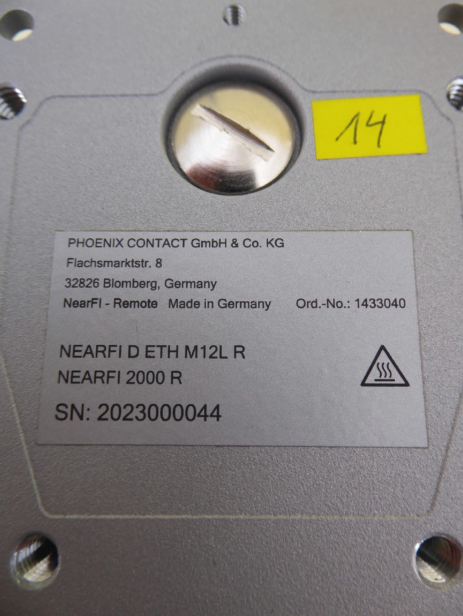
YG32000R
May 03, 2026Ultra Short Range Communication Device (USRD)
Equipment Class
DXX - Part 15 Low Power Communication Device Transmitter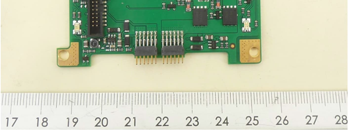
YG3300R
May 03, 2026Wireless Power Transfer
Equipment Class
JAB - Part 15 Class B Digital Device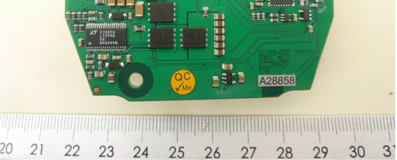
YG3300B
May 03, 2026Wireless Power Transfer
Equipment Class
8CC - Part 18 Consumer Device
YG3200R
May 03, 2026Wireless Power Transfer
Equipment Class
JAB - Part 15 Class B Digital Device
YG3200B
May 03, 2026Wireless Power Transfer
Equipment Class
8CC - Part 18 Consumer Device