YG7-PWQ51N00Powerline Wireless N
Zinwell Corporation
Click to zoom
Application Details
- Equipment Class
- DTS - Digital Transmission System
- Date of Grant
- Sep 27, 2012
- Application Purpose
- Original Equipment
- Date of Application
- Sep 26, 2012
- Equipment Note
- Powerline Wireless N
- Frequency Range
- 2412.00000000 - 2462.00000000
- Company
- Zinwell Corporation
- Country
- Taiwan
Documents & Files
Document Text
Text extracted from the exhibit documents filed with the FCC. Open a document above to read the original.
Users Manual
802.11n + HomePlug AV Embedded antenna Low Power Consumption Powerline Wireless N Extender PWQ‐5101 User Manual 2 Preface This product is a wireless AP device with PowerLine Communication (PLC) capability. With its newest 500Mbps PLC technologies (Homeplug AV), crossing-floor communication in a concrete building, which has been a big problem of wireless networking, become very reliable. Its cutting edge 802.11n wireless technology provides the highest wireless throughput for devices in the same floors. Its embedded 1T1R MIMO antenna makes it the easiest for wall installations. This product is suitable for general users to install in their home/houses, while advanced configuration through web-browser described in later chapters is suitable for the experienced users who installs and manages the Powerline Wireless N Extender products (hereafter referred to as the “device”). To use these chapters, you should have experience working with the TCP/IP configuration and be familiar with the concepts and terminology of wireless local area networks. 3 Important Safety Notes This product is intended for connection to the AC power line. For installation instructions, refer to the Installation section. The following precautions should be taken when using this product. Please read all instructions before installing and operating this product. Please keep all instructions for later reference. Please follow all warnings and instructions marked on the product. For safety reason, when device is being powered on, this product should NOT be installed in any electric socket which makes the surface with venting holes on the product to face downward (facing the floor). Unplug the Powerline device from the wall outlet before cleaning. Use a dry cloth for cleaning. DO NOT use liquid cleaners or aerosol cleaners. DO NOT operates this product near water. This product should never be placed near or over a radiator, or heat register. This product relies on the building’s electrical installation for short-circuit (over current) protection. DO NOT allow anything to rest on the product interconnect plug. DO NOT locates this product where people may walk on the cords. Because this product sends data over the power line, it is recommended that you plug directly into a power outlet. Do not plug the device into a UPS or power strip with surge protection. The product has its own power filter for protection against surges. Only a qualified technician should service this product. Opening or removing covers may result in exposure to dangerous voltage points or other risks. Unplug the product from the wall outlet and refer the product to qualified service personnel for the following conditions: When the interconnect cords are damaged or frayed. If liquid has been spilled into the product. If the product has been exposed to rain or water. If the product does not operate normally when the operating instructions are followed. If the product exhibits a distinct change in performance. 4 TABLET of CONTENT CH 1. PRODUCT OVERVIEW..............................................................................................6 Packing List ....................................................................................................................................................... 6 Buttons and LEDs ............................................................................................................................................. 6 CH 2. HARDWARE INSTALLATION ...................................................................................9 Application 1 – Link to remote DSL via Powerline ........................................................................................ 9 Application 2 – wireless AP + Ethernet switch ............................................................................................ 10 Application 3– multiple floor home networking........................................................................................... 10 Application 4– Powerline Ethernet switch ................................................................................................... 12 Application 5 – AP client adapter .................................................................................................................. 12 Fast Encryption by Buttons ........................................................................................................................... 13 CH 3. ADVANCED SETTING – VIA WEB BROWSER ......................................................16 Before Starting Configure .............................................................................................................................. 16 Operation Mode............................................................................................................................................... 16 Setup Wizard ................................................................................................................................................... 17 Internet Settings.............................................................................................................................................. 18 LAN Settings-------------------------------------------------------------------------------------------------------------------- 18 DHCP Clients-------------------------------------------------------------------------------------------------------------------- 20 Wireless Settings ............................................................................................................................................ 20 Basic-------------------------------------------------------------------------------------------------------------------------------20 Advanced------------------------------------------------------------------------------------------------------------------------- 22 Security------------------------------------------------------------------------…
Text truncated - open the document above for the full version.
External Photos
Report No.: 128380R-RFUSP42V01 Page : 1 of 3 ٛٛ Attachment 2 : EUT Detailed Photographs (1) EUT Photo (2) EUT Photo Report No.: 128380R-RFUSP42V01 Page : 2 of 3 ٛٛ (3) EUT Photo (4) EUT Photo Report No.: 128380R-RFUSP42V01 Page : 3 of 3 ٛٛ (5) EUT Photo
ID Label/Location Info
ZINWELL CORPORATION FCC ID.: YG7-PWQ51N00 7F., No.512, Yuanshan Rd., Zhonghe Dist., New Taipei City 235, Taiwan (R.O.C.)Tel : 886-2-22251929 FCC ID Label
ID Label/Location Info
ZINWELL CORPORATION FCC ID.: YG7-PWQ51N00 7F., No.512, Yuanshan Rd., Zhonghe Dist., New Taipei City 235, Taiwan (R.O.C.)Tel : 886-2-22251929 The FCC ID will be placed on the equipment as shown in the photograph below.
Internal Photos
Report No.: 128380R-RFUSP42V01 Page : 1 of 8 ٛٛ Attachment 2 : EUT Detailed Photographs (6) EUT Photo (7) EUT Photo Report No.: 128380R-RFUSP42V01 Page : 2 of 8 ٛٛ (8) EUT Photo (9) EUT Photo Report No.: 128380R-RFUSP42V01 Page : 3 of 8 ٛٛ (10) EUT Photo (11) EUT Photo Report No.: 128380R-RFUSP42V01 Page : 4 of 8 ٛٛ (12) EUT Photo (13) EUT Photo Report No.: 128380R-RFUSP42V01 Page : 5 of 8 ٛٛ (14) EUT Photo (15) EUT Photo Report No.: 128380R-RFUSP42V01 Page : 6 of 8 ٛٛ (16) EUT Photo (17) EUT Photo Report No.: 128380R-RFUSP42V01 Page : 7 of 8 ٛٛ (18) EUT Photo (19) EUT Photo Report No.: 128380R-RFUSP42V01 Page : 8 of 8 ٛٛ (20) EUT Photo
Test Report
Report No. 128380R-RFUSP42V01 Page : 1 of 112 Test Report Product Name Powerline Wireless N Extender Model No PWQ-5101 FCC ID. YG7-PWQ51N00 Applicant ZINWELL CORPORATION Address 7F., No.512, Yuanshan Rd., Zhonghe Dist., New Taipei City 235, Taiwan (R.O.C.) Date of Receipt Aug. 17, 2012 Issue Date Sep. 11, 2012 Report No. 128380R-RFUSP42V01 Report Version V1.0 The test results relate only to the samples tested. The test report shall not be reproduced except in full without the written approval of QuieTek Corporation. This report must not be used to claim product endorsement by NVLAP any agency of the U.S. Government Report No. 128380R-RFUSP42V01 Page : 2 of 112 Test Report Certification Issue Date: Sep. 11, 2012 Report No.: 128380R-RFUSP42V01 Product Name Powerline Wireless N Extender Applicant ZINWELL CORPORATION Address 7F., No.512, Yuanshan Rd., Zhonghe Dist., New Taipei City 235, Taiwan (R.O.C.) Manufacturer ZINWELL CORPORATION Model No. PWQ-5101 FCC ID. YG7-PWQ51N00 EUT Rated Voltage AC 100-240V, 50-60Hz EUT Test Voltage AC 120V/60Hz Trade Name Applicable Standard FCC CFR Title 47 Part 15 Subpart C: 2010 ANSI C63.4: 2003 Test Result Complied The test results relate only to the samples tested. The test report shall not be reproduced except in full without the written approval of QuieTek Corporation. This report must not be used to claim product endorsement by NVLAP any agency of the U.S. Government Documented By : ( Adm. Specialist / Joanne Lin ) Tested By : ( Engineer / Jack Hsu ) Approved By : ( Manager / Vincent Lin ) Report No. 128380R-RFUSP42V01 Page : 3 of 112 TABLE OF CONTENTS Description Page 1. GENERAL INFORMATION .....................................................................................................5 1.1. EUT Description............................................................................................................................5 1.2. Operational Description ................................................................................................................7 1.3. Tested System Details....................................................................................................................8 1.4. Configuration of Tested System ....................................................................................................8 1.5. EUT Exercise Software .................................................................................................................8 1.6. Test Facility ...................................................................................................................................9 2. Conducted Emission..................................................................................................................10 2.1. Test Equipment............................................................................................................................10 2.2. Test Setup ....................................................................................................................................10 2.3. Limits ..........................................................................................................................................11 2.4. Test Procedure .............................................................................................................................11 2.5. Uncertainty ..................................................................................................................................11 2.6. Test Result of Conducted Emission.............................................................................................12 3. Peak Power Output ...................................................................................................................14 3.1. Test Equipment............................................................................................................................14 3.2. Test Setup ....................................................................................................................................14 3.3. Limits ..........................................................................................................................................14 3.4. Test Procedure .............................................................................................................................14 3.5. Uncertainty ..................................................................................................................................14 3.6. Test Result of Peak Power Output...............................................................................................15 4. Radiated Emission .....................................................................................................................19 4.1. Test Equipment............................................................................................................................19 4.2. Test Setup ....................................................................................................................................20 4.3. Limits ..........................................................................................................................................21 4.4. Test Procedure .............................................................................................................................22 4.5. Uncertainty ..................................................................................................................................22 4.6. Test Result of Radiated Emission................................................................................................23 5. RF antenna conducted test........................................................................................................39 5.1. Test Equipment............................................................................................................................39 5.2. Test Setup ..............…
Text truncated - open the document above for the full version.
Test Report
Report No. 128380R-RFUSP42V01 Page : 63 of 112 Channel 07 (2452MHz) Report No. 128380R-RFUSP42V01 Page : 64 of 112 Report No. 128380R-RFUSP42V01 Page : 65 of 112 6. Band Edge 6.1. Test Equipment RF Conducted Measurement The following test equipments are used during the band edge tests: Equipment Manufacturer Model No./Serial No. Last Cal. Spectrum Analyzer R&S FSP40 / 100170 Jun, 2012 Spectrum Analyzer Agilent E4407B / US39440758 Jun, 2012 X Spectrum Analyzer Agilent N9010A / MY48030495 Apr., 2012 Note: 1. All equipments are calibrated with traceable calibrations. Each calibration is traceable to the national or international standards. 2. The test instruments marked with “X” are used to measure the final test results. RF Radiated Measurement: The following test equipments are used during the band edge tests: Test Site Equipment Manufacturer Model No./Serial No. Last Cal. Bilog Antenna Schaffner Chase CBL6112B/2673 Sep., 2012 X Horn Antenna Schwarzbeck BBHA9120D/D305 Sep., 2012 Horn Antenna Schwarzbeck BBHA9170/208 Jul., 2012 X Pre-Amplifier Agilent 8447D/2944A09549 Sep., 2012 X Spectrum Analyzer Agilent E4407B / US39440758 May, 2012 Test Receiver R & S ESCS 30/ 825442/018 Sep., 2012 X Coaxial Cable QuieTek QTK-CABLE/ CAB5 Feb., 2012 X Controller QuieTek QTK-CONTROLLER/ CTRL3 N/A Site # 3 X Coaxial Switch Anritsu MP59B/6200265729 N/A Note: 1. All instruments are calibrated every one year. 2. The test instruments marked by “X” are used to measure the final test results. Report No. 128380R-RFUSP42V01 Page : 66 of 112 6.2. Test Setup RF Conducted Measurement RF Radiated Measurement: 6.3. Limits Emissions radiated outside of the specified frequency bands, except for harmonics, shall be attenuated by at least 20dB below the level of the fundamental or to the general radiated emission limits in paragraph 15.209, whichever is the lesser attenuation. EUT FRP Dome The height of broad band or Dipole Antenna was scanned from 1M to 4M. The distance between antenna and turn table was 3M regards to the standard ado pted. 3m 80cm To Receiver Pre- Amplifier SMA EUT Spectrum Analyzer RF Cable Report No. 128380R-RFUSP42V01 Page : 67 of 112 6.4. Test Procedure The EUT was setup according to ANSI C63.4: 2003 and tested according to DTS test procedure of Jan. 2012 KDB558074 for compliance to FCC 47CFR 15.247 requirements. The EUT is placed on a turn table which is 0.8 meter above ground. The turn table is rotated 360 degrees to determine the position of the maximum emission level. The EUT was positioned such that the distance from antenna to the EUT was 3 meters. The antenna is scanned from 1 meter to 4 meters to find out the maximum emission level. This is repeated for both horizontal and vertical polarization of the antenna. In order to find the maximum emission, all of the interface cables were manipulated according to ANSI C63.4: 2003 on radiated measurement. 6.5. Uncertainty ± 3.9 dB above 1GHz ± 3.8 dB below 1GHz Report No. 128380R-RFUSP42V01 Page : 68 of 112 6.6. Test Result of Band Edge Product : Powerline Wireless N Extender Test Item : Band Edge Data Test Site : No.3 OATS Test Mode : Mode 1: Transmit (802.11b 1Mbps) (2412MHz) RF Radiated Measurement (Horizontal): Channel No. Frequency (MHz) Correct Factor (dB) Reading Level (dBuV) Emission Level (dBuV/m) Peak Limit (dBuV/m) Arerage Limit (dBuV/m) Result 01 (Peak) 2390.000 31.509 24.229 55.738 74.00 54.00 Pass 01 (Peak) 2413.000 31.646 73.688 105.334 -- -- Pass 01 (Average) 2390.000 31.509 13.403 44.912 74.00 54.00 Pass 01 (Average) 2409.400 31.621 69.460 101.080 -- -- Pass Figure Channel 01: Horizontal (Peak) Figure Channel 01: Horizontal (Average) Note: 1. All readings above 1GHz are performed with peak and/or average measurements as necessary. 2. Peak measurements: RBW = 1MHz, VBW = 3 MHz, Sweep: Auto. 3. Average measurements: RBW = 1MHz, VBW = 10 Hz, Sweep: Auto. 4. “ * ”, means this data is the worst emission level. 5. Measurement Level = Reading Level + Correct Factor. 6. The average measurement was not performed when the peak measured data under the limit of average detection. Report No. 128380R-RFUSP42V01 Page : 69 of 112 Product : Powerline Wireless N Extender Test Item : Band Edge Data Test Site : No.3 OATS Test Mode : Mode 1: Transmit (802.11b 1Mbps) (2412MHz) RF Radiated Measurement (VERTICAL): Channel No. Frequency (MHz) Correct Factor (dB) Reading Level (dBuV) Emission Level (dBuV/m) Peak Limit (dBuV/m) Arerage Limit (dBuV/m) Result 01 (Peak) 2389.200 30.919 24.522 55.441 74.00 54.00 Pass 01 (Peak) 2390.000 30.915 22.920 53.835 74.00 54.00 Pass 01 (Peak) 2413.000 30.956 73.489 104.445 -- -- Pass 01 (Average) 2390.000 30.915 13.573 44.488 74.00 54.00 Pass 01 (Average) 2411.200 30.944 69.560 100.504 -- -- Pass Figure Channel 01: VERTICAL (Peak) Figure Channel 01: VERTICAL (Average) Note: 1. All readings above 1GHz are performed with peak and/or average measurements as necessary. 2. Peak measurements: RBW = 1MHz, VBW = 3 MHz, Sweep: Auto. 3. Average measurements: RBW = 1MHz, VBW = 10 Hz, Sweep: Auto. 4. “ * ”, means this data is the worst emission level. 5. Measurement Level = Reading Level + Correct Factor. 6. The average measurement was not performed when the peak measured data under the limit of average detection. Report No. 128380R-RFUSP42V01 Page : 70 of 112 Product : Powerline Wireless N Extender Test Item : Band Edge Data Test Site : No.3 OATS Test Mode : Mode 1: Transmit (802.11b 1Mbps) (2462MHz) RF Radiated Measurement (Horizontal): Channel No. Frequency (MHz) Correct Factor (dB) Reading Level (dBuV) Emission Level (dBuV/m) Peak Limit (dBuV/m) Arerage Limit (dBuV/m) Result 11 (Peak) 2460.900 32.011 75.016 107.027 -- -- Pass 11 (Peak) 2483.500 32.182 25.100 57.282 74.00 54.00 Pass 11 (Peak) 2487.500 32.212 26.788 59.000 74.00 54.00 Pass 11 (Average) 2461.100 32.013 71.123 103.136 -- -- Pass 11 (Average) 2483.500 32.182 14.728 46.910 74.00 54.00 Pass Figure Channel 11: Horizontal (Peak) Figure Channel 11: Horizontal (Average) Note:…
Text truncated - open the document above for the full version.
Test Setup Photos
Report No.: 128380R-RFUSP42V01 Page : 1 of 3 ٛٛ Attachment 1: EUT Test Setup Photographs Front View of Conducted Test Back View of Conducted Test Report No.: 128380R-RFUSP42V01 Page : 2 of 3 ٛٛ Front View of Radiated Test Back View of Radiated Test Report No.: 128380R-RFUSP42V01 Page : 3 of 3 ٛٛ Front View of Radiated Test (Horn) Back View of Radiated Test (Horn)
Contact Information
Applicant
Gary Tsai(Senior Manager)
Technical Contact
Test Firm
DEKRA TESTING AND CERTIFICATION CO., LTD. LinKouMirenda Liao
Technical Specifications
| # | Rule Parts | Frequency Range | Power Output |
|---|---|---|---|
| 1 | 15C | 2.41 GHz - 2.46 GHz | 180.00 mW |
Other Applications from Zinwell Corporation
YG79X327915
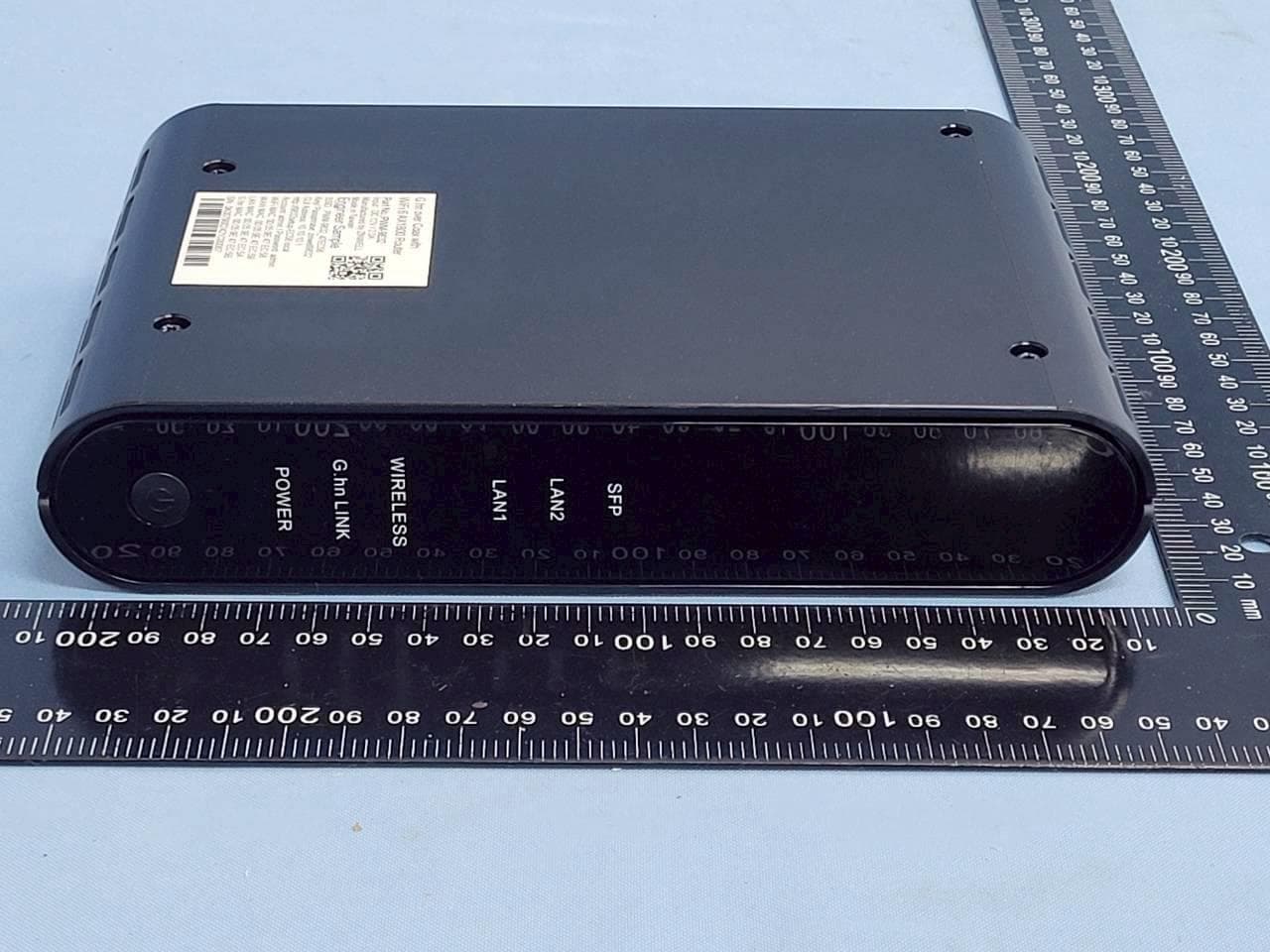
Mar 12, 2026G.hn over Coax with WiFi 6 AX1800 Router
Equipment Class
DTS - Digital Transmission System
YG7ZAT6000L2106
Jul 26, 2021ATSC3.0 STB
Equipment Class
DTS - Digital Transmission System
YG7BM23SPK
Nov 08, 2015G6, USA receptacle, Bluetooth
Equipment Class
DSS - Part 15 Spread Spectrum Transmitter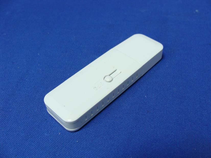
YG7ZIN2100T
Oct 05, 2011PC to TV Transmission Kit
Equipment Class
DTS - Digital Transmission System
YG7RF31200M
Aug 29, 2011Wireless HD Net Connect Transmitter
Equipment Class
DTS - Digital Transmission System