YGKR6360Bluetooth Mono Headset
SHENZHEN ROMAN TECHNOLOGY CO.,LTD.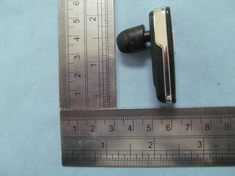
Click to zoom
Application Details
- Equipment Class
- DSS - Part 15 Spread Spectrum Transmitter
- Date of Grant
- Mar 04, 2012
- Application Purpose
- Original Equipment
- Date of Application
- Mar 04, 2012
- Equipment Note
- Bluetooth Mono Headset
- Frequency Range
- 2402.00000000 - 2480.00000000
- Country
- China
Documents & Files
Document Text
Text extracted from the exhibit documents filed with the FCC. Open a document above to read the original.
Users Manual
Bluetooth Mono Headset User’s Manual Model : R6360 R5 R505 R510 R515 R520 R525 R535 R550 R565 R560 R570 FCC ID:YGKR6360 Charging the battery Bluetooth has an internal, no removable, Li-Polymer rechargeable batter y. Do not attempt to remove the batter y from the device as you may damage the device. Please do not use the device while being charged. 1. For first time use, please fully charge the headset. 2. Connect the charger to a wall ou tlet and connects the charger cable to the charger socket. 3. While the charger is connected, the red indicator light is displayed during charging. Charging the batter y fully may take up to 1 hour. 4. When the batter y is fully charged, the red indicator light turns off and the blue indicators will solid light, please disconnect the charger from the headset and the wall outlet. 5. The fully charged batter y can keep the power up to 4 hours of talk-time. When the headset is powered on and batter y power is low, the headset will emits reminder tones every 20 seconds in the earphone, and the indicator light will turn red. Batter y information 1. Your device is powered by a Li-Polymer ch argeable batter y. The full performance of a new batter y is an achieved only after two or three complete charge and discharge cycles. The battery can be charged and discharged hundreds of times, but it will eventually wear out. 2. Unplug the charger from the electrical plug and the device when not in use. Do not leave a fully charged batter y connected to a charger, since overcharging may shorten its lifetime. If left unused, a fully charged batter y will lose its charge over time. I t is recommended that you fully charge the headset before leaving it unused for a long time. To prevent over discharge endangers the batter y, you are recommended to fully charge the headset ever y 2 months. Basic Operation Before you use the headset for the first time, you must pair it with your Bluetooth ® mobile phone or other Bluetooth ® devices ( The “Device”). In this user guide, we take mobile phone as the pairing object for example. Please pair according to the following steps: 1)Place the headset and the device within 1 meter distance area. 2)Ensure the headset is off, then press Multi-function Button for 5 seconds until the blue and red light fl ash alternately ; the headset is on pairing mode now. 3) Activate your mobile's Bluetooth ® functions by referring to your mobile user guide for details. Make the mobile to search for the Bluetooth ® device. 4) Your mobile phone will find the headset and show it on the list. 5) Select the name , afte r press “OK” to confirm, input the password “0000” to finish pairing. 6) When the headset is paired with mobile phone, you will hear a beep and the blue indicator light will flash 5 times quickly, and then enter the standby state. ® 7 )When the headset is in the pairing mode, if you didn’t finish the pairing process within 2 minute, the headset will enter the standby state. If you want to pair again, you need to repeat the steps 1)-6). 8) If your master device is compliant to Bluetooth v2.1 specification, the headset may not ask password. 9) The headset supports multi-point technology, if you want to connect the headset to the second Bluetooth- enabled mobile, please repeat the pairing operation steps above. When complete pairing, turn off the headset and then turn on again, the headset will connect to both 2 mobiles automatically. Wearing your headset 1. The headset is provided with an ear hook that you can use for a better fit on your ear. 2.To use the headset without the ear hook, plug the headset into you ear and point the headset toward your mouth. 3. To use the headset with the ear hook, insert the ear hook into the small opening at the back of the headset. 4. The headset can be worn on either the left or right ear by change the direction of the ear hook. Turning headset on /off Turning on the headset When the headset is turned off, pr ess and hold the MFB for about 2s, the headset will emit 2 beeps, and the blue indicator will flash at the same time, the headset is now on. Connecting to a Bluetooth ® - enabled mobile phone If the headset has completed the pairing operation successfully, when the headset turns on, it will connect to the phone(s) you last connected automatically. Please ensure your phone(s)'s Bluetooth ® function is activated. Turning off the headset At any working state after the headset is powered on, press and hold MFB for about 4s, the headset will emit 2 beeps, and the red indicator will flash at the same time, the headset is powered off now. Important: When the headset has connected to 2 mobiles phones, it should be distinguished the connection sequence for some operations. As our definition, the phone first connected to headset is phone 1, the second one is phone 2. If the headset is out of range, it will automatically try to reconnect the device for 5 times. To conserve power, if the headset is not connected to a device in 1hour, the headset will turn off automatically. Head-free function Making a call-Using phone's keypad In the stand-by mode, you can dial the number on your phone(s)'s keypad to make a call. Use Voice -Dialing In the stand-by mode, press MFB briefly, you will hear a short tone from the headset, and the phone will prompt you say the voice tag which you have already attached to your contact. If the voice tag is identified by the phone, the related number will be dialed. Please insure that your mobile phone supports this voice dialing function ,and voice tags have been set up on your mobile phone prior to attempting this. Please refer to your mobile phone's user guide or contact your ser vice provider. Important: In a state of multi- connection is existed, the voice - dialing function is only available for phone 1. Last number re - dialing In the stand-by mode, double press MFB the last number you dialed will be re - dialed. Important: In a state of multi- connection is existed, the last number re - di…
Text truncated - open the document above for the full version.
Cover Letter(s)
March 2, 2012 Federal Communication Commission Authorization and Evaluation Division FCC ID: YGKR6360 Re: Confidentiality Request Pursuant to Sections 0.457 and 0.459 of the Commission’s Rules, the applicant hereby requests confidential treatment of information applied this application as outlined below: 1: Block Diagram 2: Circuit Diagram 3: Operational Description 4: Parts List The above materials contain trade secrets and proprietary information not customarily released to the public. The public disclosure of these matters might be harmful to the applicant and provide unjustified benefits to its competitors. The Applicant understands that pursuant to Rules 0.457, disclosure of this Application and all accompanying documentation will not be made before the date of the Grant for this application. Sincerely, SHENZHEN ROMAN TECHNOLOGY CO.,LTD.
External Photos
TOP VIEW OF EUT BOTTOM VIEW OF EUT LEFT VIEW OF EUT RIGHT VIEW OF EUT FRONT VIEW OF EUT BACK VIEW OF EUT
ID Label/Location Info
Bluetooth mono headset FCC ID: YGKR6360 Model Name:R6360 Brand Name:ROMAN R6360/R5/R505/R510/ R515/R520/R525/R535 /R550/R565/R560/R57
Internal Photos
OPEN VIEW-1 OF EUT OPEN VIEW-2 OF EUT FRONT VIEW OF PCB BACK VIEW OF PCB Bluetooth Antenna
Test Report
FCC Test Report Report No.: AGC035120201F2 FCC ID : YGKR6360 PRODUCT DESIGNATION : Bluetooth mono headset BRAND NAME : ROMAN TEST MODEL : R6360 CLIENT : SHENZHEN ROMAN TECHNOLOGY CO.,LTD. DATE OF ISSUE : Mar.01, 2012 STANDARD(S) : FCC Part 15 Rules Attestation of Global Compliance Co., Ltd. CAUTION: This report shall not be reproduced except in full without the written permission of the test laboratory and shall not be quoted out of context. Report No.: AGC035120201F2 Page 1 of 37 VERIFICATION OF COMPLIANCE Applicant SHENZHEN ROMAN TECHNOLOGY CO.,LTD. Floor4,buildingC,Fengmenao Industrial Park,Gangtou ,Shenzhen,China Manufacturer SHENZHEN ROMAN TECHNOLOGY CO.,LTD. Floor4,buildingC,Fengmenao Industrial Park,Gangtou ,Shenzhen,China Product Designation Bluetooth mono headset Brand Name ROMAN Model Name R6360, R5, R505, R510, R515, R520, R525, R535, R550, R565, R560, R570 Model Difference And Test Model All above models are the same except for the appearance. The test model is R6360. FCC ID YGKR6360 Report Number AGC035120201F2 Date of Test Feb.28, 2012 to Mar.01, 2012 WE HEREBY CERTIFY THAT: The above equipment was tested by Attestation of Global Compliance Co., Ltd. The test data, data evaluation, test procedures, and equipment configurations shown in this report were made in accordance with the procedures given in ANSI C63.4 (2003) and the energy emitted by the sample EUT tested as described in this report is in compliance with radiated emission limits of FCC Rules Part 15.247. Tested By: Curoky Chen Mar.01, 2012 Reviewed By: Forrest Lei Mar.01, 2012 Approved By: Solger Zhang Mar.01, 2012 Report No.: AGC035120201F2 Page 2 of 37 TABLE OF CONTENTS 1. GENERAL INFORMATION .................................................................................................................................................... 4 1.1 PRODUCT DESCRIPTION .............................................................................................................................................. 4 1.2 TABLE OF CARRIER FREQUENCYS .......................................................................................................................... 4 1.3 RECEIVER INPUT BANDWIDTH ................................................................................................................................... 5 1.4 EXAMPLE OF A HOPPING SEQUENCY IN DATA MODE ........................................................................................ 6 1.5 EQUALLY AVERAGE USE OF FREQUENCIES AND BEHAVIOUR ....................................................................... 6 1.6 RELATED SUBMITTAL(S) / GRANT (S) ...................................................................................................................... 6 1.7 TEST METHODOLOGY ................................................................................................................................................... 6 1.8 MEASUREMENT UNCERTAINTY ................................................................................................................................. 6 1.9 TEST FACILITY ................................................................................................................................................................. 7 1.10 SPECIAL ACCESSORIES ............................................................................................................................................ 7 1.11 EQUIPMENT MODIFICATIONS ................................................................................................................................... 7 2. SYSTEM TEST CONFIGURATION ...................................................................................................................................... 8 2.1 CONFIGURATION OF TESTED SYSTEM .................................................................................................................... 8 2.2 EQUIPMENT USED IN EUT SYSTEM .......................................................................................................................... 8 3. SUMMARY OF TEST RESULTS ........................................................................................................................................... 9 4. DESCRIPTION OF TEST MODES ....................................................................................................................................... 9 5. PEAK OUTPUT POWER ..................................................................................................................................................... 10 5.1 MEASUREMENT PROCEDURE .................................................................................................................................. 10 5.2 TEST SET-UP (BLOCK DIAGRAM OF CONFIGURATION) ................................................................................... 10 5.3 MEASUREMENT EQUIPMENT USED ........................................................................................................................ 11 5.4 LIMITS AND MEASUREMENT RESULT .................................................................................................................... 11 6. 20 DB BANDWIDTH ............................................................................................................................................................. 12 6.1 MEASUREMENT PROCEDURE .................................................................................................................................. 12 6.2 TEST SET-UP (BLOCK DIAGRAM OF CONFIGURATION) ................................................................................... 12 6.3 MEASUREMENT EQUIPMENT USED ........................................................................................................................ 12 6.4 LIMITS AND MEASUREMENT RESULTS .................................................................................................................. 12 7. CONDUCTED SPURIOU…
Text truncated - open the document above for the full version.
Test Setup Photos
RADIATED SPURIOUS EMISSION
Contact Information
Applicant
Yanhui Cao
Test Firm
Attestation of Global Compliance Shenzhen Co. Ltd.Forrest Lei
Technical Specifications
| # | Rule Parts | Frequency Range | Power Output |
|---|---|---|---|
| 1 | 15C | 2.40 GHz - 2.48 GHz | 2.30 mW |
Other Applications from SHENZHEN ROMAN TECHNOLOGY CO.,LTD.
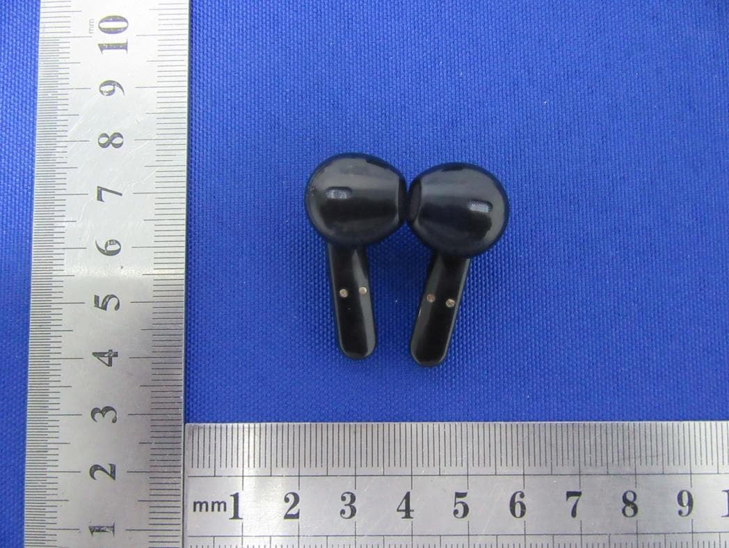
YGKTS16C
May 19, 2021Bluetooth Headset
Equipment Class
DSS - Part 15 Spread Spectrum Transmitter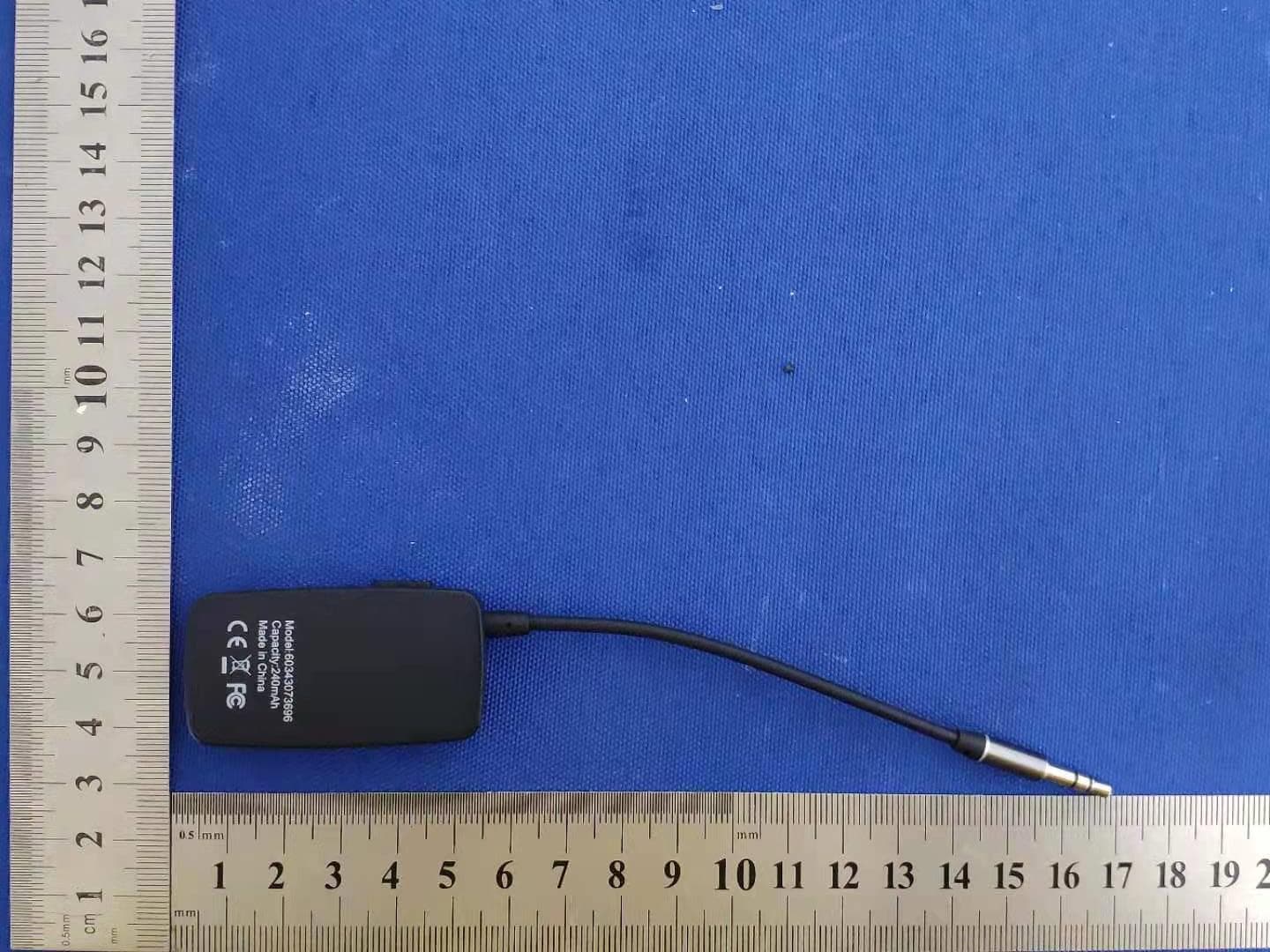
YGK-J205
Mar 06, 2021Bluetooth receiver
Equipment Class
DSS - Part 15 Spread Spectrum Transmitter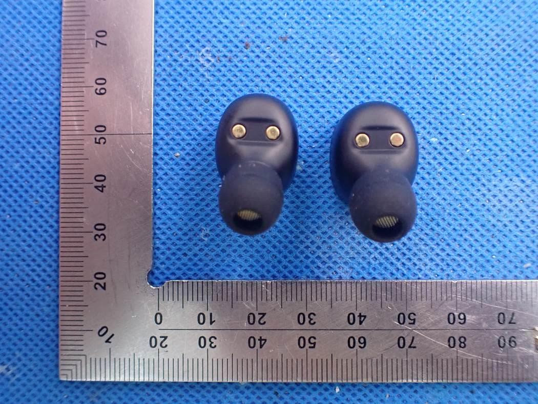
YGK-T302A
Sep 23, 2020Bluetooth Headset
Equipment Class
DSS - Part 15 Spread Spectrum TransmitterYGKR6100
Nov 16, 2015Bluetooth headset
Equipment Class
DXX - Part 15 Low Power Communication Device Transmitter
YGKS370
Mar 16, 2015Bluetooth Headset
Equipment Class
DXX - Part 15 Low Power Communication Device Transmitter