YGU-TS03Foot warmer remote control
Reinbacher International Limited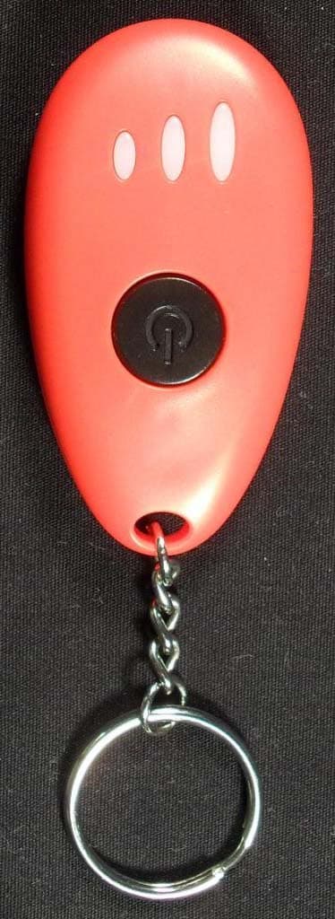
Click to zoom
Application Details
- Equipment Class
- DSC - Part 15 Security/Remote Control Transmitter
- Date of Grant
- Jul 25, 2010
- Application Purpose
- Original Equipment
- Date of Application
- Jul 25, 2010
- Equipment Note
- Foot warmer remote control
- Frequency Range
- 434.00000000 - 434.00000000
- Country
- Hong Kong
Documents & Files
Document Text
Text extracted from the exhibit documents filed with the FCC. Open a document above to read the original.
Users Manual
Page 1 of 4 (05/26/10) ThermaCELL ® Heated Insoles Welcome to ThermaCELL ® Technology Dear ThermaCELL® Heated Insoles Purchaser: We are pleased that you made the decision to purchase ThermaCELL Heated Insoles, featuring wireless remote control and rechargeable embedded Lithium-Ion Polymer batteries. Your purchase features patented rechargeable Heated Insoles with Remote Control ON/OFF heat operation. The ThermaCELL self-contained advanced heat technology is great for cold weather activities. The technology enables purchasers to remotely control temperature adjustments while wearing shoes or boots. Operating Instructions included within this document provide clear and concise directions on how to set up your Insoles for remote control temperature operation. ThermaCELL products, including the ThermaCELL mosquito repellant product line, have enabled outdoor enthusiasts to enjoy their activities (hunting, fishing, camping, etc) with confidence and in comfort. We thank you for your purchase of ThermaCELL Heated Insoles and are confident that, as a result, your cold weather activities will be more comfortable and enjoyable. Enjoy your purchase. The ThermaCELL Product Group Page 2 of 4 (05/26/10) ThermaCELL ® Heated Insoles Operating Instructions PACKAGE CONTENTS The ThermaCELL® Heated Insoles box contains two Heated Insoles, one Remote Control Unit, one Global Charger, and one Drawstring Travel Bag. GETTING STARTED The ThermaCELL Heated Insoles must be fully charged until the LED light on the Global Charger turns from Red to Green. This may take up to 6 hours for the first charge. Subsequent charges will take about 3 hours. The ON/OFF Switch and Recharge Port, located at the back of both insoles (in the heel area), are protected by a soft plastic black cap. CHARGING IMPORTANT: both Insoles must be charged at the same time while following these steps: 1. Set the ON/OFF Switch on each Insole to the left position (“OFF”). 2. Plug the Global Charger into the wall receptacle. The LED light on the Global Charger will glow Green. 3. Plug in Global Charger cables into each Insole Recharge Port, which can be found at the heel of the Insole. The LED light on the Global Charger will turn Red once connections have been established. 4. After charging is complete, the LED light on the Global Charger will turn Green. 5. Unplug the Global Charger and remove the cables from both Insoles. The ThermaCELL Heated Insoles are now ready to be used. TO ACTIVATE THE INSOLES 1. Turn each heated Insole on by moving the ON/OFF Switch at the heel of the Insole to the right position (“ON”). 2. Unpack the Remote Control unit and remove the protective tab to enable the already installed replaceable battery to activate. 3. Press and immediately release the black button on the Remote Control unit. The left LED light on the Remote Control unit will flash Red several times to indicate that the Insoles are now in Standby mode. 4. Press the black button again within 4 seconds and release to cycle through the existing temperature settings (Standby – Medium 100°F – High 111°F). a. The LED light on the Remote Control unit will flash several times after being activated: Standby – left light Red Medium – center light Green High – right light Green 5. The Red LED lights at the heel of the Insoles will blink continuously as follows: Standby - one blink Page 3 of 4 (05/26/10) Medium (100°F) - two blinks High (111°F) - three blinks 6. Insert the Insoles into shoes or boots. 7. Use the Remote Control unit to operate the Insoles while shoes or boots are on feet. TO TURN OFF THE INSOLES Turn the ON/OFF Switch at the heel of the Insoles to the left position (“OFF”). Remote Control unit will turn off automatically when Insoles are turned off. THE INTERGRATED LITHIUM-ION POLYMER BATTERIES The high-quality Lithium-Ion Polymer batteries (no memory effect) can be re-charged approximately 500 times. The batteries are embedded in the Insole material and cannot be accessed. For best performance it is recommended to occasionally drain the batteries of both Insoles completely before re-charging. To do this, turn the insoles ON using the ON/OFF Switch at the heel of the insole, use the Remote Control unit to put the insoles on the high setting (LED on Remote Control unit blinks 3 times), and then run the Insoles until the LED lights on the Insoles turn OFF The batteries will reach their maximum power after having been drained and re-charged several times. Do not fully charge the batteries if the Insoles will not be used for a long period of time. Charge the Insoles for 20 minutes only and then again for 20 minutes after 3 months of storage. Charge completely before using the Insoles again. If the battery in the Remote Control unit is running low, the Low-Battery Alert will start flashing in sequence from Standby – Medium – High, etc. In this case, follow the instructions below on how to replace the battery in the Remote Control unit. REMOTE CONTROL BATTERY REPLACEMENT The Remote Control unit comes equipped with one Lithium Cell # CR2032. To replace the battery: 1. Remove the two small Phillips screws on the underside of the Remote Control unit. 2. Lay both sides of the Remote Control unit open on a table and dislodge the battery from the appropriate side. 3. Replace the battery, making certain that the positive (“+”) side of the battery is face up. 4. Place the two sides of the Remote Control unit together and secure with the two small Phillips screws. GENERAL COMMENTS TO ASSIST IN ENJOYING THE USE OF THE HEATED INSOLES If needed, remove any existing insoles from shoes or boots to assist in making a perfect fit for the ThermaCELL Heated Insoles. The tabs at the end of the ThermaCELL Heated Insoles will assist in easy removal of the Insoles from shoes or boots after use. Page 4 of 4 (05/26/10) Once the Heated Insoles have been charged, depending on the outside temperature and quality of the shoes or boots, the Insoles will operate for …
Text truncated - open the document above for the full version.
Users Manual
Page 1 of 5 (07/20/10) ThermaCELL ® Heated Insoles Welcome to ThermaCELL ® Technology Dear ThermaCELL® Heated Insoles Purchaser: We are pleased that you made the decision to purchase ThermaCELL Heated Insoles, featuring wireless remote control and rechargeable embedded Lithium-Ion Polymer batteries. Your purchase features patented rechargeable Heated Insoles with Remote Control ON/OFF heat operation. The ThermaCELL self-contained advanced heat technology is great for cold weather activities. The technology enables purchasers to remotely control temperature adjustments while wearing shoes or boots. Operating Instructions included within this document provide clear and concise directions on how to set up your Insoles for remote control temperature operation. ThermaCELL products, including the ThermaCELL mosquito repellant product line, have enabled outdoor enthusiasts to enjoy their activities (hunting, fishing, camping, etc) with confidence and in comfort. We thank you for your purchase of ThermaCELL Heated Insoles and are confident that, as a result, your cold weather activities will be more comfortable and enjoyable. Enjoy your purchase. The ThermaCELL Product Group Page 2 of 5 (07/20/10) ThermaCELL ® Heated Insoles Instruction Booklet PACKAGE CONTENTS The ThermaCELL® Heated Insoles box contains two Heated Insoles, one Remote Control Unit, one Global Charger, and one Drawstring Travel Bag. GETTING STARTED Instructions for Cutting Insoles to Size: The insoles are constructed in such a way, that the size can be trimmed to fit shoes or boots if needed. Be sure to follow the WARNING statement printed on the bottom of the insoles! The two cutting lines are for reference only. Caution: Do not cut beyond the solid line or excessively bend the insoles. This will cause damage to the heating elements and the product. Charging: The ThermaCELL Heated Insoles must be fully charged until the LED light on the Global Charger turns from Red to Green. This may take up to 6 hours for the first charge. Subsequent charges will take about 3 hours. The ON/OFF Switch and Recharge Port, located at the back of both insoles (in the heel area), are protected by a soft plastic black cap. HOW TO CHARGE INSOLES IMPORTANT: both Insoles must be charged at the same time while following these steps: 1. Set the ON/OFF Switch on each Insole to the left position (“OFF”). 2. Plug the Global Charger into the wall receptacle. The LED light on the Global Charger will glow Green. 3. Plug in Global Charger cables into each Insole Recharge Port, which can be found at the heel of the Insole. The LED light on the Global Charger will turn Red once connections have been established. 4. After charging is complete, the LED light on the Global Charger will turn Green. 5. Unplug the Global Charger and remove the cables from both Insoles. The ThermaCELL Heated Insoles are now ready to be used. TO ACTIVATE THE INSOLES 1. Turn each heated Insole on by moving the ON/OFF Switch at the heel of the Insole to the right position (“ON”). 2. Unpack the Remote Control unit and remove the protective tab to enable the already installed replaceable battery to activate. Page 3 of 5 (07/20/10) 3. Press and immediately release the black button on the Remote Control unit. The left LED light on the Remote Control unit will flash Red several times to indicate that the Insoles are now in Standby mode. 4. Press the black button again within 4 seconds and release to cycle through the existing temperature settings (Standby – Medium 100°F – High 111°F). a. The LED light on the Remote Control unit will flash several times after being activated: Standby – left light Red Medium – center light Green High – right light Green 5. The Red LED lights at the heel of the Insoles will blink continuously as follows: Standby - one blink Medium (100°F) - two blinks High (111°F) - three blinks 6. Insert the Insoles into shoes or boots. 7. Use the Remote Control unit to operate the Insoles while shoes or boots are on feet. TO TURN OFF THE INSOLES 1. Turn the ON/OFF Switch at the heel of the Insoles to the left position (“OFF”). 2. Remote Control unit will turn off automatically when Insoles are turned off. REMOTE CONTROL BATTERY REPLACEMENT The Remote Control unit comes equipped with one Lithium Cell # CR2032. To replace the battery: 1. Remove the two small Phillips screws on the underside of the Remote Control unit. 2. Lay both sides of the Remote Control unit open on a table and dislodge the battery from the appropriate side. 3. Replace the battery, making certain that the positive (“+”) side of the battery is face up. 4. Place the two sides of the Remote Control unit together and secure with the two small Phillips screws. THE INTERGRATED LITHIUM-ION POLYMER BATTERIES • The high-quality Lithium-Ion Polymer batteries (no memory effect) can be re-charged approximately 500 times. • The batteries are embedded in the Insole material and cannot be accessed. • For best performance it is recommended to occasionally drain the batteries of both Insoles completely before re-charging. To do this, turn the insoles ON using the ON/OFF Switch at the heel of the insole, use the Remote Control unit to put the insoles on the high setting (LED on Remote Control unit blinks 3 times), and then run the Insoles until the LED lights on the Insoles turn OFF Page 4 of 5 (07/20/10) The batteries will reach their maximum power after having been drained and re-charged several times. • Do not fully charge the batteries if the Insoles will not be used for a long period of time. Charge the Insoles for 20 minutes only and then again for 20 minutes after 3 months of storage. Charge completely before using the Insoles again. • If the battery in the Remote Control unit is running low, the Low-Battery Alert will start flashing in sequence from Standby – Medium – High, etc. In this case, follow the instructions below on how to replace the battery in the Remote Control unit. P P R R O O P P E E R R D D I I S S P P O …
Text truncated - open the document above for the full version.
Block Diagram
REINBACHER INTERNATIONAL LIMITED Room 1603 Citicorp Centre 18 Whitfield Road, North Point, Hong Kong Tel: (852) 2895 2401 Fax: (852) 2571 9216 E-mail: [email protected] Block Diagram for Transmit ter – RC Unit of TS-03
ID Label/Location Info
Wireless Remote FISHERDESIGN 42179_1wmd_TC_remote | 06.07.10 FCC ID: YGU-TS03 IC:9030A-TS03 TS03 R Thermo Soles
Operational Description
ThermaCELL FootWarmers Operating Instructions 1. To charge both soles (both soles must be charged at the same time): a. Plug the charger into a wall outlet. The Green light on the charger will turn on. b. Connect both charging plugs on the charger to the charging sockets at the back of the soles. Make sure that the On/Off switch at the back of both soles is in the “Off” position (move switch position to the left). c. The light on the charger will turn red. d. Charging is complete when the light on the charger turns green. 2. To activate the soles: a. Turn the On/Off switch on the soles to the On position (move to the right). b. Press the button and release. The left most light (red) on the remote will turn on to indicate the remote is on the Standby setting. c. Press and release the button on the remote to move through the temperature settings (Standby, Medium, High). d. In Parallel, the LED light on the soles (to the left of the switch) will blink. i. One blink indicates Standby ii. Two blinks indicate Medium iii. Three blinks indicate High e. The lights on the sole should blink continuously when in use. 3. To turn off the soles: a. Turn the switch on the soles to the Off position.
Test Report
Client: Product Designation: TS-03 Report Number: 100112160ATL-001 All services undertaken are subject to the following general policy: This report is for the exclusive use of Intertek's Client and is provided pursuant to the agreement between Intertek and its Client. Intertek's responsibility and liability are limited to the terms and conditions of the agreement. Intertek assumes no liability to any party, other than to the Client in accordance with the agreement, for any loss, expense or damage occasioned by the use of this report. Only the Client is authorized to copy or distribute this report and then only in its entirety. Any use of the Intertek name or one of its marks for the sale or advertisement of the tested material, product or service must first be approved in writing by Intertek. The observations and test results in this report are relevant only to the sample tested. This report by itself does not imply that the material, product, or service is or has ever been under an Intertek certification program. This report must not be used to claim product endorsement by A2LA, NIST, or any agency of the US Government. Tested by: Tests performed by:Report reviewed by: Standard: Jeremy O. Pickens EMC Department Manager Troy J. Ihle EMC Project Engineer Schawbel Cor p (The) 26 Crosby Drive Bedford, MA 01730 Contact: Yigal Offir Phone: 866.753.3837 TEST REPORT July 14, 2010 Intertek Testing Services NA Inc. 1950 Evergreen Blvd., Suite 100 Duluth, GA 30096 47 CFR Part 15, Subpart C (15.231 - Periodic operation in the band 40.66- 40.70 MHz and above 70 MHz) RSS-210, Issue 7, 2007 Page 1 of 22EMC Report for Schawbel Corp (The) on the TS-03 07/14/2010Report Number: 100112160ATL-001Issued: Intertek 2.0 Test Summary 1.0 Introduction and Conclusion Test DateTest Full NameResultSection System setup including cable interconnection details, support equipment and simplified block diagram. (System Setup)4.0 Overview of EUT (Low Power Transmitters) (FCC 15C - EUT Overview)5.0 06/02/2010Restrictions (FCC 15C - 15.231(a))PASS6.0 05/21/2010Duty Cycle Determination (FCC 15A - 15.35(c))7.0 07/07/2010Radiated Emissions (FCC 15C - 15.231(b))PASS8.0 05/21/2010Bandwidth Requirements (FCC 15C - 15.231(c))PASS9.0 Conducted emissions on AC power lines (Conducted Emissions) was waived due to the EUT is battery-operated.NA Conducted Emissions for Intentional Radiators (FCC 15C - 15.207) was waived due to the EUT is battery-operated.NA The tests indicated in section 2.0 were performed on the product constructed as described in section 3.0. The remaining test sections are the verbatum text from the actual data sheets used during the investigation. These test sections include the test name, the specified test Method, a list of the actual Test Equipment Used, documentation Photos, Results and raw Data. No additions, deviations, or exclusions have been made from the standard(s) unless specifically noted. Based on the results of our investigation, we have concluded the product tested complies with the requirements of the standard(s) indicated. The results obtained in this test report pertain only to the item(s) tested. Page 2 of 22EMC Report for Schawbel Corp (The) on the TS-03 07/14/2010Report Number: 100112160ATL-001Issued: Intertek 3.0 Description of Equipment Under Test Equipment Under Test Description Manufacturer Model Number Serial Number ThermaCell FootWarmer Remote The Schawbel Corporation TS-03 Not Labeled EUT receive date: May 21 and July 7, 2010 EUT receive condition: Good Description of EUT provided by Client: The TS-03 Transmitter is used to wirelessly control an in-sole heater placed in the user’s shoe. Description of EUT exercising: During testing, the device was configured to transmit continuously. Page 3 of 22EMC Report for Schawbel Corp (The) on the TS-03 07/14/2010Report Number: 100112160ATL-001Issued: Intertek System setup including cable interconnection details, support equipment and simplified block diagram. (System Setup) 4.0 Method: Record the details of EUTcabling, document the support equipment, and show the interconnections in a block diagram. Description EUT Cabling Connection Length Shielding FerritesIDFromTo No Cables Present Support Equipment DescriptionManufacturerModel NumberSerial Number No support equipment required Data: Page 4 of 22EMC Report for Schawbel Corp (The) on the TS-03 07/14/2010Report Number: 100112160ATL-001Issued: Intertek Overview of EUT (Low Power Transmitters) (FCC 15C - EUT Overview)5.0 Method: Complete the overview spreadsheet. Related Submittal(s) Grants: This report is for use with an application for certification of a low power transmitter. One transmitter is included in the application. The Schawbel Corporation 26 Crobs y Drive Bedford , MA 01730 Trade Name & Model No. Foot Warmer Remote & TS-03 FCC Identifier YGU-TS03 IC Id en tifier 9030A -TS03 Frequency Range (MHz) 434 A nten na Typ e (15.203) In teg ral The Schawbel Corporation 26 Crobs y Drive Bedford , MA 01730 Additions, deviations and exclusions from standards This report is for use with an application for certification of a low power transmitter. One transmitter is included in the application. Applicant Manufacturer name & address Related Submittals and Grants: Data: Page 5 of 22EMC Report for Schawbel Corp (The) on the TS-03 07/14/2010Report Number: 100112160ATL-001Issued: Intertek Restrictions (FCC 15C - 15.231(a))6.0 Method: 15.231(a) The provisions of this section are restricted to periodic operation within the band 40.66-40.70 MHz and above 70 MHz. Except as shown in paragraph (e) of this section, the intentional radiator is restricted to the transmission of a control signal such as those used with alarm systems, door openers, remote switches, etc. Continuous transmissions, voice, video and the radio control of toys are not permitted. Data is permitted to be sent with a control signal. The following conditions shall be met to comply with the provisions for this periodic operation: (1) A manually op…
Text truncated - open the document above for the full version.
Contact Information
Applicant
Albert Au(Manager)
Test Firm
Intertek Testing Services NA Inc.Charles Parker
Technical Specifications
| # | Rule Parts | Frequency Range | Power Output |
|---|---|---|---|
| 1 | 15.231 | 434 MHz - 434 MHz | - |
Other Applications from Reinbacher International Limited
YGU-TS03S
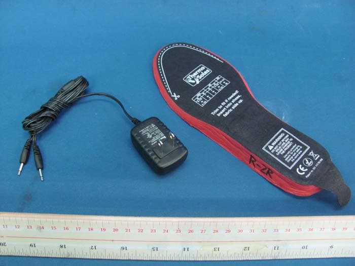
Jan 06, 2011Heated Insoles With Rechargeable Batteries
Equipment Class
CYY - Communications Receiver used w/Pt 15 Transmitter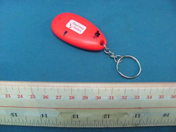
YGU-TS03RC
Jan 06, 2011Heated Insoles With Rechargeable Batteries
Equipment Class
DSC - Part 15 Security/Remote Control Transmitter