YGU-TS03SHeated Insoles With Rechargeable Batteries
Reinbacher International Limited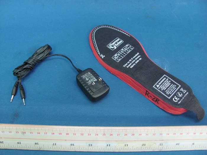
Click to zoom
Application Details
- Equipment Class
- CYY - Communications Receiver used w/Pt 15 Transmitter
- Date of Grant
- Jan 06, 2011
- Application Purpose
- Original Equipment
- Date of Application
- Jan 06, 2011
- Equipment Note
- Heated Insoles With Rechargeable Batteries
- Frequency Range
- 433.92000000 - 433.92000000
- Country
- Hong Kong
Documents & Files
Document Text
Text extracted from the exhibit documents filed with the FCC. Open a document above to read the original.
Users Manual
CONTENTS: INHALT: CONTENU: • 2 Heated Insoles 2 beheizbare Sohlen 2 semelles chauffantes • 1 Remote Control unit 1 Fernbedienung 1 Remote Control unit • 1 Adapter 1 Adapter 1 chargeur • 1 Storage & Travel pouch 1 Trage & Reisetasche 1 housse de rangement et de transport • 1 Instruction booklet 1 Gebrauchsanweisung 1 notice d’utilisation Technical Specifications: • 900 mAh Li-Ion Polymer Battery • Heating time up to 6 hours • Soletemperature :38°C - 44°C Technische Hinweise: • 900 mAh Li-Ionen Batterie • Betriebsdauer bis zu 6 Stunden • Temperatur von 38°C - 44°C DONNÉES TECHNIQUES: • Batterie polymère 900 mAh Li-Ion • Durée de chauffage jusqu’à 6 heures • Température de la semelle entre 38°C et 44°C • Protective non-conducting layer • Schutzeinlage • couche de protection en matériau non conducteur • Insulating fabric lining • Isoliermaterial • revêtement isolant • Protective cover • Schutzkappe • volet de protection • Tab • Lasche • languette PATENTED Patent Number: DE 103 52 050 A1 International patents pending! German Technology Made in China Warning: Changes or modifications to this unit not expressly approved by the party responsible for compliance could void the user’s authority to operate the equipment. RoHS C o m p l i a n t 2002/95/EC THERMO SOLES Instructions THERMO SOLES Gebrauchsanweisung THERMO SOLES Mode d’emploi ® • 3-D Polyurethane footbed • 3-D Polyurethan Fußbett • chausson polyuréthane anatomique • Fabric Lining • Obermaterial • revêtement en tissus • Remote Control • Thermostat • Thermostat • Thermostat • Li-Ion Polymer Battery • Li-Ion Polymer Batterie • batterie Lithium Ion polymère • LED Lamp • LED Lampe • LED • On/Off Switch • Ein/ Aus Schalter • interrupteur marche/arrêt • Receiver • PCB Board • PCB Board • circuit imprimé sur film flexible • Heating element • Heizelement • élément chauffant • Control chip • Kontroll- Chip • circuit électronique de contrôle • Adaptor socket • Adapter Anschluss • prise de connexion au chargeur NoNo LADEN: 1) Beide Sohlen müssen gleichzeitig geladen werden. 2) Öffnen Sie die Schutzabdeckung über der Schalt- / Ladeeinheit. 3) Schieben Sie den ON/OFF Schalter nach links in die OFF Position. 4) Stecken Sie das Ladegerät in eine geeignete Steckdose, das grüne Licht am Ladegerät leuchtet auf. 5) Stecken Sie jetzt die beiden am Ladegerät befindlichen Stecker in die dafür vorgesehenen Ladebuchsen der Sohlen. Das Ladegerät leuchtet rot, die Sohlen werden geladen. 6) Sobald die Sohlen geladen sind, wechselt das Licht am Ladegerät auf grün. 7) Entfernen Sie nun die Kabel von den Sohlen, sowie das Ladegerät aus der Steckdose. 8) Ihre Sohlen sind jetzt einsatzbereit. Unpack the THERMOSOLES Foot Warmers, remote unit and adapter. THERMOSOLES Foot Warmers must be fully charged for 8 hours before first use! The ON/OFF switch, located on the back of the soles, is protected by a soft plastic cap. Open the cap and set the On/Off switch to the left OFF position. CHARGING: (Both soles always must be charged at the same time!) 1) Set the On/Off switch to the left OFF position. 2) Plug in the charger into a wall outlet. The green light of the charger will now turn on. 3) Plug in the charger cables to both of the soles sockets. The red light on the charger will now turn on, indicating that the soles are charging. 4) After charging is complete, the green light on the charger will turn on. 5) Unplug the charger and remove the charger cables from the soles. Your THERMOSOLES Foot Warmers are now ready to be used. ACTIVATE THE SOLES: 1) Turn the On/Off switch to the right ON position for soles to receive signal from remote unit. 2) Remove the protective tab on the remote unit (before its first use!). 3) Press the button on the remote unit and release. The left light (red) on the remote unit will flash several times to indicate that the soles are now on a Standby setting. 4) Press the button and release again to move through the required temperature settings (Standby 5°C – Medium 38°C – High 44°C). The cycle of the setting is Standby – Medium – High – Standby, etc.! 5) The LED lights on the remote unit will flash several times after being activated: Standby – left light in red. Medium – middle light in green. High – right light in green. 6) The red LED lights on the back of the soles will blink continuously as follows: Standby – One blink. Medium (38°C) – Two blinks. High (44°C) – Three blinks. OPERATING INSTRUCTIONS CONSEILS D’UTILISATION TURN OFF THE SOLES: Turn the On/Off switch to the left OFF position. BATTERIES: • The high-quality 900 mAh Li-Ion Polymer batteries (no memory effect!) can be re-charged approximately 500 times! • The batteries will reach their maximum power after having been drained and re-charged several times! • For best performance it is recommended to occasionally drain the batteries of both soles completely before recharging! • Do not fully charge the batteries if the soles will not be used for an extended period of time. Charge the batteries for 20 minutes only and then again for 20 minutes after 3 months of storage. Charge completely before using the soles again! • If the battery of the Remote Unit is running low, the Low Battery Alert will start flashing in sequence from Standby – Medium – High, etc.! In this case, please contact your nearest THERMOSOLES dealer or replace with 1 piece of CR2032 button cell battery. GENERAL COMMENTS FOR EASY USAGE OF THE SOLES: • If needed, remove any existing in-soles from your shoes or boots in order to guarantee a perfect fit of your soles. • The tabs at the end of the soles will help you to easily remove the soles from your shoes or boots after use. • The maximum heating time, depending on the outside temperatures and quality of your shoes or boots, is approximately 6 hours. (On Medium setting!) CARE INSTRUCTIONS: • Turn OFF the soles when not in use. • Store the soles and adapter in a clean and dry place. • Only use the enclosed original adapter to charge the soles. • Only charge the soles when th…
Text truncated - open the document above for the full version.
Block Diagram
RX3310A Block Diagram
External Photos
INTERTEK TESTING SERVICE Report No.: HK10110996-2 FCC ID: YGU-TS03S Equipment Photographs Model : TS03RC (External)
ID Label/Location Info
Trim to fit if needed! Insert into shoes, fabric side up. DO NOT CUT BEYOND SOLID LINE, MAY CAUSE DAMAGE TO THE PRODUCT. Use only provided adaptor for charging. Charge both soles at the same time. WARNING: Patent no. DE 103 52 050 ON OFF USA M 5-1/2 to 4-1/2 W 7 to 6 M 5 to 4 W 4-1/2 to 3-1/2 37-1/2 to 36 UKEU This device complies with part 15 of the FCC Rules. Operation is subject to the following two conditions: (1) This device may not cause harmful interference, and (2) this device must accept any interference received, including interference that may cause undesired operation. Trim to fit if needed! Insert into shoes, fabric side up. DO NOT CUT BEYOND SOLID LINE, MAY CAUSE DAMAGE TO THE PRODUCT. Use only provided adaptor for charging. Charge both soles at the same time. WARNING: Patent no. DE 103 52 050 ON OFF USA M 5-1/2 to 4-1/2 W 7 to 6 M 5 to 4 W 4-1/2 to 3-1/2 37-1/2 to 36 UKEU This device complies with part 15 of the FCC Rules. Operation is subject to the following two conditions: (1) This device may not cause harmful interference, and (2) this device must accept any interference received, including interference that may cause undesired operation. FCC ID: YGU-TS03SFCC ID: YGU-TS03S size: 19 x 34mm size: 2.6 x 29mm
Internal Photos
INTERTEK TESTING SERVICE Report No.: HK10110996-2 FCC ID: YGU-TS03S Equipment Photographs Model : TS03RC (Internal) INTERTEK TESTING SERVICE Report No.: HK10110996-2 FCC ID: YGU-TS03S Equipment Photographs Model : TS03RC (Internal) INTERTEK TESTING SERVICE Report No.: HK10110996-2 FCC ID: YGU-TS03S Equipment Photographs Model : TS03RC (Internal) INTERTEK TESTING SERVICE Report No.: HK10110996-2 FCC ID: YGU-TS03S Equipment Photographs Model : TS03RC (Internal)
Operational Description
FCC ID: YGU-TS03S Technical Description : The brief circuit description is listed as follows : - U3 and associated circuit acts as decoder and RF Super- heterodyne Receiver. - U1 and associated circuit act as MCU. - Q1 and associated circuit act as thermo circuit driver. - Q2 and associated circuit act as signal circuit switch. - Q3, Q4 and associated circuit act as temperature control driver. - U2 act as voltage regulator. - RT act as temperature detector. - R201 – R207 act as thermo heater components. Antenna Used : An integral antenna (non-extensible) has been used.
Schematics
BAT1 3.7V Li-ion C2 1u 123 JP1 R1 300 R410K R3 23.2K 1% R7 300 SW1 SS-12D33 R2510K JACK1 DC5V 500mA R9 47K R3a U2 TL431 R8 47K Q1 2SB1424 R5 75 R10 10K LED1 Red C5 10n RF解调输入 温度档输出控制 Low/OFF Mid Hi P62P63 00 01 10 2.5V P52/ADC2 1 P53/ADC3 2 P54/TCC/Vref 3 /RESET 4 VSS 5 P60//INT 6 P61/TCCA 7 P62/TCCB 8 P63/TCCC 9 CO/P64 10 CIN+/P65 11 CIN-/P66 12 IR OUT/P67 13 VDD 14 OSCO/P70 15 OSCI/P55 16 ADC0/P50 17 ADC1/P51 18 U1 EM78P259NM OSC1 20 OSC2 1 FO 2 CPA 3 CPB 4 CPO 5 VSS 7 DATA 8 DISABLE 9 CPC 10 LIN 11 VCC 12 LFB 13 VIRF 14 VEE 15 VORF 16 MIXIN 17 VCC 18 VCC 19 VSS 6 U3 RX3310A C19 100p C12 82p C15 10p C14 5.6p C13 1.2p C16 10n C11 470p C7 3p Ct2 8.2p C8 100p C9 470p C10 1u C18 10n C17 47u L2 82nH L3 18nH L1 4.5T ANT Ct1 3p R12 1K L46.8uH Q2 8550 R11 4.3K Q4 8050 Q3 8050 R14 6.2K 1% R16 8.2K 1% R15 10K R13 10K C3 10n R17 10K R18 10K R19 10K R204.3K R21 22K C6 470p RT 10K 123 JP1A R201 56 R202 56 R203 56 R204 56 R207 56 R205 56 R206 56
Test Report
Report no.: HK10110996-2 Mode: Charging mode Ctrl No.: N/A 150 kHz30 MHz 1 PK CLRWR 2 AV CLRWR SGL TDS 6DB dBμV dBμV AC RBW 9 kHz MT 1 s PREAMP OFFAtt 10 dB AUTO 1 MHz10 MHz 0 10 20 30 40 50 60 70 80 90 100 CF15MAV CF15MQP HK10110996-2 (K09962C1) Date: 2.DEC.2010 17:24:09 Report no.: HK10110996-2 Mode: Charging mode Ctrl No.: N/A EDIT PEAK LIST (Final Measurement Results) Trace1: CF15MQP Trace2: CF15MAV Trace3: --- TRACE FREQUENCY LEVEL dBμV DELTA LIMIT dB 1 Quasi Peak 177 kHz 46.45 N -18.17 1 Quasi Peak 235.5 kHz 41.91 N -20.34 1 Quasi Peak 334.5 kHz 31.03 N -28.30 1 Quasi Peak 532.5 kHz 36.00 N -19.99 2 CISPR Average600 kHz 28.82 N -17.17 1 Quasi Peak 730.5 kHz 38.23 L1 -17.76 2 CISPR Average807 kHz 25.88 L1 -20.11 1 Quasi Peak 811.5 kHz 37.23 L1 -18.76 1 Quasi Peak 1.248 MHz 30.32 N -25.67 1 Quasi Peak 2.076 MHz 33.24 N -22.75 2 CISPR Average2.085 MHz 27.62 N -18.38 1 Quasi Peak 2.9265 MHz 34.03 N -21.96 2 CISPR Average2.949 MHz 28.28 N -17.71 1 Quasi Peak 3.0975 MHz 35.85 L1 -20.14 2 CISPR Average3.705 MHz 28.91 L1 -17.08 1 Quasi Peak 4.587 MHz 37.26 L1 -18.73 2 CISPR Average4.6815 MHz 29.83 N -16.16 1 Quasi Peak 5.7885 MHz 35.80 L1 -24.19 HK10110996-2 (K09962C1) Date: 2.DEC.2010 17:24:02
Test Report
Intertek Testing Services Hong Kong Ltd. 2/F., Garment Centre, 576 Castle Peak Road, Kowloon, Hong Kong. Tel: (852) 2173 8888 Fax: (852) 2785 5487 Website: www.hk.intertek-etlsemko.com TEST REPORT Report No.: HK10110996-2 Reinbacher International Limited Application For Certification (Original Grant) (FCC ID: YGU-TS03S) Superheterodyne Receiver Prepared and Checked by: Approved by: Signed On File Kenneth Wong /cl Engineer Chan Chi Hung, Terry Assistant Supervisor Date: January 05, 2011 INTERTEK TESTING SERVICES Report No.: HK10110996-2 FCC ID: YGU-TS03S i GENERAL INFORMATION Reinbacher International Limited BRAND NAME: THERMO SOLES , MODEL: TS03RC FCC ID: YGU-TS03S Grantee: Reinbacher International Limited Grantee Address: Room 1603 Citicorp Centre, 18 Whitfield Road, North Point, Hong Kong Contact Person: Albert Au Tel: 2895 2401 Fax: 2571 9216 e-mail: [email protected] Manufacturer: Dongguan Jing Cheng Electronic Co. Ltd. Manufacturer Address: Chung Hang, Shek Pai District, Dongguan, Guangdong Province, China (Postal Code: 523332) Brand Name: THERMO SOLES Model: TS03RC Type of EUT: Superheterodyne Receiver Description of EUT: Heated Insoles With Rechargeable Batteries Serial Number: N/A FCC ID: YGU-TS03S Date of Sample Submitted: November 24, 2010 Date of Test: December 07, 2010 Report No.: HK10110996-2 Report Date: January 05, 2011 Environmental Conditions: Temperature: +10 to 40°C Humidity: 10 to 90% INTERTEK TESTING SERVICES Report No.: HK10110996-2 FCC ID: YGU-TS03S ii SUMMARY OF TEST RESULT Reinbacher International Limited BRAND NAME: THERMO SOLES, MODEL: TS03RC FCC ID: YGU-TS03S TEST SPECIFICATION REFERENCE RESULTS Maximum Peak Output Power 15.247(b), (c) / RSS-210 A8.4 N/A Hopping Channel Carrier Frequencies Separation 15.247(e) / RSS-210 A8.1 N/A 20dB Bandwidth of the Hopping Channel 15.247(a) / RSS-210 A8.1 N/A Number of Hopping Frequencies 15.247(e) / RSS-210 A8.1 N/A Average Time of Occupancy of Hopping Frequency 15.247(e) / RSS-210 A8.1 N/A Antenna Conducted Spurious Emissions 15.247(d) / RSS-210 A8.5 N/A Radiated Spurious Emissions 15.247(d) / RSS-210 A8.5 N/A RF Exposure Compliance 15.247(i) / RSS-Gen 5.5 N/A Transmitter Power Line Conducted Emissions 15.207 / RSS-Gen 7.2.2 N/A Transmitter Field Strength 15.227 / RSS-310 3.8 N/A Transmitter Field Strength 15.229 / RSS-210 A2.7 N/A Transmitter Field Strength, Bandwidth and Timing Requirement 15.231(a) / RSS-210 A1.1.1 N/A Transmitter Field Strength, Bandwidth and Timing Requirement 15.231(e) / RSS-210 A1.1.5 N/A Transmitter Field Strength and Bandwidth Requirement 15.239 / RSS-210 A2.8 N/A Transmitter Field Strength and Bandwidth Requirement 15.249 / RSS-210 A2.9 N/A Transmitter Field Strength and Bandwidth Requirement 15.235 / RSS-310 3.9 N/A Receiver / Digital Device Radiated Emissions 15.109 / ICES-003 Pass Receiver / Digital Device Conducted Emissions 15.107 / ICES-003 Pass Note: 1. The EUT uses a permanently attached antenna which, in accordance to section 15.203, is considered sufficient to comply with the pervisions of this section. 2. Pursuant to FCC part 15 Section 15.215(c), the 20 dB bandwidth of the emission was contained within the frequency band designated (mentioned as above) which the EUT operated. The effects, if any, from frequency sweeping, frequency hopping, other modulation techniques and frequency stability over excepted variations in temperature and supply voltage were considered. INTERTEK TESTING SERVICES Report No.: HK10110996-2 FCC ID: YGU-TS03S iii Table of Contents 1.0 General Description....................................................................................... 1 1.1 Product Description ...................................................................................... 1 1.2 Related Submittal(s) Grants .......................................................................... 1 1.3 Test Methodology ......................................................................................... 1 1.4 Test Facility .................................................................................................. 1 2.0 System Test Configuration ............................................................................ 2 2.1 Justification................................................................................................... 2 2.2 EUT Exercising Software .............................................................................. 2 2.3 Special Accessories...................................................................................... 2 2.4 Equipment Modification................................................................................. 2 2.5 Measurement Uncertainty ............................................................................. 2 2.6 Support Equipment List and Description........................................................ 2 3.0 Emission Results ........................................................................................... 3 3.1 Field Strength Calculation ............................................................................. 3 3.2 Radiated Emission Configuration Photograph ............................................... 4 3.3 Radiated Emission Data ............................................................................... 4 3.4 Conducted Emission Configuration Photograph ............................................ 4 3.5 Conducted Emission Data............................................................................. 4 4.0 Equipment Photographs ................................................................................ 7 5.0 Product Labelling ........................................................................................... 7 6.0 Technical Specifications ................................................................................ 7 7.0 Instruction Manual......................................................................................... 7 8.0 Miscellaneous Information ......................…
Text truncated - open the document above for the full version.
Test Setup Photos
INTERTEK TESTING SERVICE Report No: HK10110996-2 FCC ID: YGU-TS03S i Configuration Photographs Worst-Case Line-Conducted Emissions (Front View) Model : TS03RC INTERTEK TESTING SERVICE Report No: HK10110996-2 FCC ID: YGU-TS03S ii Configuration Photographs Worst-Case Line-Conducted Emissions (Back View) Model : TS03RC INTERTEK TESTING SERVICE Report No: HK10110996-2 FCC ID: YGU-TS03S iii Configuration Photographs Worst-Case Line-Conducted Emissions (Side View) Model : TS03RC
Test Setup Photos
INTERTEK TESTING SERVICE Report No: HK10110996-2 FCC ID: YGU-TS03S Configuration Photographs Worst-Case Radiated Emissions (Front View) Receiving mode Model : TS03RC Radiated Emission Model: TS03RC Job: HK10110996-2 A5 B INTERTEK TESTING SERVICE Report No: HK10110996-2 FCC ID: YGU-TS03S Configuration Photographs Worst-Case Radiated Emissions (Back View) Receiving mode Model : TS03RC Radiated Emission Model: TS03RC Job: HK10110996-2 A B5 INTERTEK TESTING SERVICE Report No: HK10110996-2 FCC ID: YGU-TS03S Configuration Photographs Worst-Case Radiated Emissions (Front View) Charging mode Model : TS03RC Radiated Emission Model: TS03RC Job: HK10110996-2 A5 B INTERTEK TESTING SERVICE Report No: HK10110996-2 FCC ID: YGU-TS03S Configuration Photographs Worst-Case Radiated Emissions (Back View) Charging mode Model : TS03RC Radiated Emission Model: TS03RC Job: HK10110996-2 A B5
Contact Information
Applicant
Albert Au(Manager)
Technical Contact
Intertek Testing Services Hong Kong LtdTerry Chan
[email protected]852-2173-8503
2/F Garment Centre · Kowloon · Hong Kong
Non-Technical Contact
Intertek Testing Services Hong Kong LtdTerry Chan
[email protected]852-2173 8503
Test Firm
Intertek Testing Services Hong Kong Ltd.Billy Chow
Technical Specifications
| # | Rule Parts | Frequency Range | Power Output |
|---|---|---|---|
| 1 | 15B | 433.92 MHz - 433.92 MHz | - |
Other Applications from Reinbacher International Limited
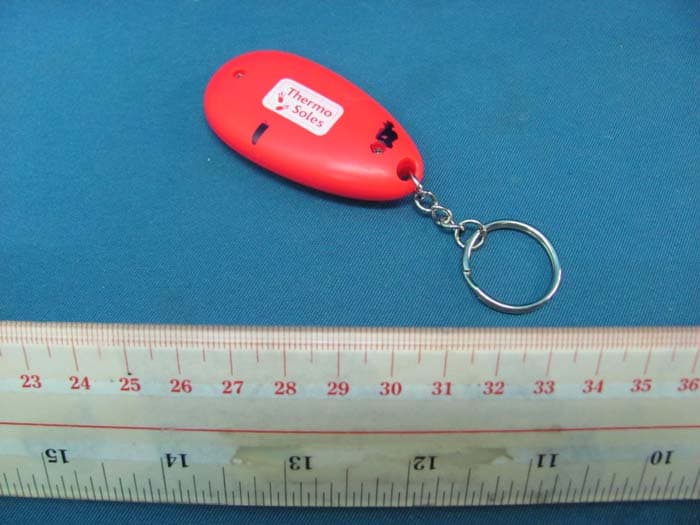
YGU-TS03RC
Jan 06, 2011Heated Insoles With Rechargeable Batteries
Equipment Class
DSC - Part 15 Security/Remote Control Transmitter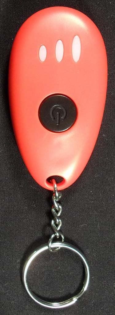
YGU-TS03
Jul 25, 2010Foot warmer remote control
Equipment Class
DSC - Part 15 Security/Remote Control Transmitter