YH9NXSMDT-OMNIPIR Occupancy/Daylight Sensor
HLI Solutions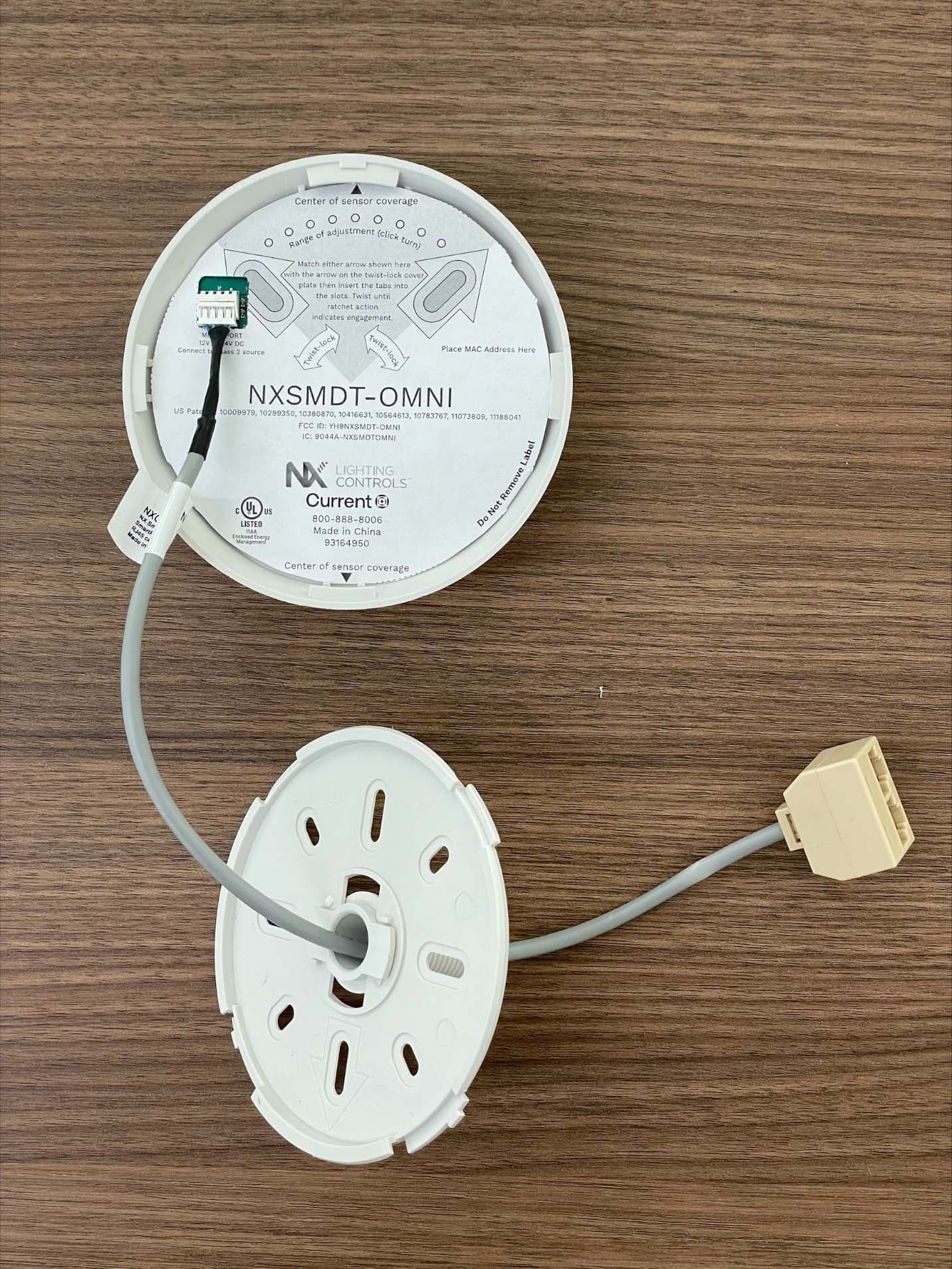
Click to zoom
Application Details
- Equipment Class
- DTS - Digital Transmission System
- Date of Grant
- Sep 26, 2022
- Application Purpose
- Original Equipment
- Date of Application
- Sep 25, 2022
- Equipment Note
- PIR Occupancy/Daylight Sensor
- Frequency Range
- 2402.00000000 - 2480.00000000
- Company
- HLI Solutions
- Country
- United States
Documents & Files
Document Text
Text extracted from the exhibit documents filed with the FCC. Open a document above to read the original.
RF Exposure Info
Project #: 23094-15 Company: Hubblell Control Solutions EUT: NXDT-OMNI RF Exposure Evaluation Report Prepared for: Hubblell Control Solutions 710 Hesters Crossing Rd., Suite 100 Round Rock, TX 78681 By Nemko PTI, Inc. 1601 North A.W. Grimes Blvd., Suite B Round Rock, Texas 78665 May 26, 2022 Written by Shakil Murad Wireless Engineer 23094-15, NXDT-OMNI Nemko PTI Page 2 of 6 Table of Contents 1.0 Maximum Permissible Exposure Evaluation (Supplements the test report.) ....................................................... 3 1.1 Applicable Documents .................................................................................................................................... 3 1.2 Criteria ............................................................................................................................................................ 3 1.3 Duty Cycle Correction Factor Measurement .................................................................................................. 4 1.4 Power to Exposure Calculation, Conducted .................................................................................................... 5 1.5 RF MPE Evaluation – FCC ............................................................................................................................. 5 1.6 RF MPE Evaluation – ISED Canada............................................................................................................... 6 1.7 Conclusion ...................................................................................................................................................... 6 NOTICE: (1) This Report must not be used to claim product endorsement, by NVLAP, NIST, the FCC or any other Agency. This report also does not warrant certification by NVLAP or NIST. (2) This report shall not be reproduced except in full, without the written approval of Nemko PTI, Inc. (3) The significance of this report is dependent on the representative character of the test sample submitted for evaluation and the results apply only in reference to the sample tested. The manufacturer must continuously implement the changes shown herein to attain and maintain the required degree of compliance. 23094-15, NXDT-OMNI Nemko PTI Page 3 of 6 1.0 Maximum Permissible Exposure Evaluation (Supplements the test report.) The measured power is considered for the intended use of the device and resulting RF exposure to the user. 1.1 Applicable Documents Table 1.1.1: Applicable Documents Document Title RSS-102 Issue 5 Radio Frequency (RF) Exposure Compliance of Radiocommunication Apparatus (All Frequency Bands) KDB 447498 D01 General RF Exposure Guidance v06 RF EXPOSURE PROCEDURES AND EQUIPMENT AUTHORIZATION POLICIES FOR MOBILE AND PORTABLE DEVICES OET Bulletin 65 Edition 97-01 Evaluating Compliance with FCC Guidelines for Human Exposure to Radiofrequency Electromagnetic Fields 1.2 Criteria Section Reference Test Detail FCC 47 CFR Part 1 I, 1.1310 // RSS-102, Issue 5 Radiofrequency radiation exposure limits 23094-15, NXDT-OMNI Nemko PTI Page 4 of 6 1.3 Duty Cycle Correction Factor Measurement Measurement is based on intervals not to exceed 100 msec. Maximum transmitter on time is divided by the lesser of 100 msec or the actual measured minimum transmitter interval time. The result is converted to dB and applied as needed to peak measurements of transmitter artifacts to determine average power. This is not a pass/fail measurement. Continuous packet transmission mode was used for the duty cycle measurement, which would represent a worst- case operating scenario. On Time (msec) Time Interval (msec) Duty Cycle (On Time/Interval) Exposure Weighing Factor (dB) (10 * Log 10 (Duty Cycle) 1.251 1.484 = 0.84 = -0.74 Plotted measurements appear below: Transmit Event TimeTime Interval (Return to channel time) 23094-15, NXDT-OMNI Nemko PTI Page 5 of 6 1.4 Power to Exposure Calculation, Conducted The EUT transmitter power is determined by conducted measurement. Safe exposure distance was calculated for the allowed maximum uncontrolled public exposure limit. Measured Conducted Peak Power (dBm) Exposure Weighing Factor (dB) Antenna Gain (dBi) Corrected Peak Power EIRP (dBm) EIRP In Linear Terms (mW) 3.39 Not used to get worse case EIRP 1.5 4.89 3.08 1.5 RF MPE Evaluation – FCC FCC 47 CFR Part 1 I, 1.1310, Radiofrequency radiation exposure limits. According to table above, the MPE limit for 2400 MHz transmitter shall not exceed power density of 1 mW/cm 2 at a distance of 20 cm from the EUT. Calculation: EIRP = 3.08 mW = 0.00308 W Distance = d = 20 cm = 0.2 m Power Density = EIRP/4πd 2 = 0.00308/4*π*(0.2) 2 = 0.0061 W/m 2 = 0.00061 mW/cm 2 Power Density 0.00061 mW/cm 2 < 1 mW/cm 2 23094-15, NXDT-OMNI Nemko PTI Page 6 of 6 1.6 RF MPE Evaluation – ISED Canada RSS-102, Section 2.5.2, Exemption Limits for Routine Evaluation – RF Exposure Evaluation RF exposure evaluation is required if the separation distance between the user and/or bystander and the device’s radiating element is greater than 20 cm, except when the device operates as follows: 1) below 20 MHz 6 and the source-based, time-averaged maximum e.i.r.p. of the device is equal to or less than 1 W (adjusted for tune-up tolerance) 2) at or above 20 MHz and below 48 MHz and the source-based, time-averaged maximum e.i.r.p. of the device is equal to or less than 4.49/ƒ0.5W (adjusted for tune-up tolerance), where ƒ is in MHz 3) at or above 48 MHz and below 300 MHz and the source-based, time-averaged maximum e.i.r.p. of the device is equal to or less than 0.6 W (adjusted for tune-up tolerance) 4) at or above 300 MHz and below 6 GHz and the source-based, time-averaged maximum e.i.r.p. of the device is equal to or less than 1.31 x 10⁻² ƒ0.6834 W (adjusted for tune-up tolerance), where ƒ is in MHz 5) at or above 6 GHz and the source-based, time-averaged maximum e.i.r.p. of the device is equal to or less than 5 W (adjusted for tune-up tolerance) Calculation: Applying equation 4 from …
Text truncated - open the document above for the full version.
Test Report
Project #: 23094-15 Company: Hubbell Control Solutions EUT: NXSMDT-OMNI FCC and Industry Canada Wireless Test Report Prepared for: Hubbell Control Solutions 710 Hesters Crossing Rd, Suite 100 Round Rock, TX 78681 By Nemko PTI, Inc. 1601 North A.W. Grimes Blvd., Suite B Round Rock, Texas 78665 May 9, 2022 Written by Shakil Murad Wireless Engineer 23094-15, NXSMDT-OMNI 22738 Professional Testing (EMI) Inc. Page 2 of 37 Table of Contents Test Result Summary .................................................................................................................................................... 5 1.0 Introduction .......................................................................................................................................................... 6 1.1 Scope ............................................................................................................................................................... 6 1.2 EUT Description ............................................................................................................................................. 6 1.3 EUT Test Mode ............................................................................................................................................... 6 1.4 EUT Test Configuration .................................................................................................................................. 6 1.5 Modifications to Equipment ............................................................................................................................ 6 1.6 Test Site .......................................................................................................................................................... 6 1.7 Measurement Corrections ............................................................................................................................... 6 1.8 Applicable Documents .................................................................................................................................... 7 2.0 Fundamental Power ............................................................................................................................................. 8 2.1 Test Procedure ................................................................................................................................................ 8 2.2 Test Criteria .................................................................................................................................................... 8 2.3 Test Results, Peak Power ................................................................................................................................ 8 3.0 Occupied Bandwidth .......................................................................................................................................... 10 3.1 Test Procedure .............................................................................................................................................. 10 3.2 Test Criteria .................................................................................................................................................. 10 3.3 Test Results, Occupied Bandwidth ............................................................................................................... 10 4.0 Duty Cycle ......................................................................................................................................................... 12 5.0 Power Spectral Density ...................................................................................................................................... 13 5.1 Test Procedure .............................................................................................................................................. 13 5.2 Test Criteria .................................................................................................................................................. 13 5.3 Test Results, Power Spectral Density ........................................................................................................... 13 6.0 Band Edge .......................................................................................................................................................... 15 6.1 Test Procedure .............................................................................................................................................. 15 6.2 Test Criteria .................................................................................................................................................. 15 6.3 Test Results ................................................................................................................................................... 15 7.0 Conducted Antenna Port Spurious Emissions, Transmit Mode ......................................................................... 17 7.1 Test Procedure .............................................................................................................................................. 17 7.2 Test Criteria .................................................................................................................................................. 17 7.3 Test Results ................................................................................................................................................... 17 7.3.1 100 kHz Bandwidth Test data ............................................................................................................. 18 7.3.2 1 MHz Bandwidth Test data ................................................................................................................ 20 8.0 Transmitter Radiated Spurious Emissions ......................................................................................................... 22 8.1 Test Procedu…
Text truncated - open the document above for the full version.
Contact Information
Applicant
Ryan Belanger
Test Firm
Professional Testing (EMI), Inc.Larry Finn
Technical Specifications
| # | Rule Parts | Frequency Range | Power Output |
|---|---|---|---|
| 1 | 15C | 2.40 GHz - 2.48 GHz | 2.20 mW |
Other Applications from HLI Solutions
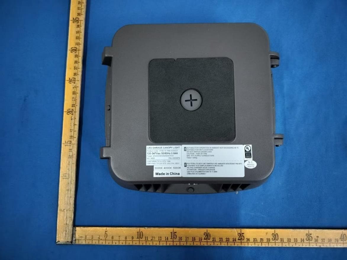
YH9LSCS
Jul 16, 2026LED GARAEG CANOPY
Equipment Class
DXX - Part 15 Low Power Communication Device TransmitterYH9NXSMP3
Sep 04, 2025Low voltage occupancy and daylight sensor with radio and built-in actuators for lighting control
Equipment Class
DTS - Digital Transmission SystemYH9NXOFM2
Sep 08, 2024On-Fixture Module for Lighting Control
Equipment Class
DTS - Digital Transmission System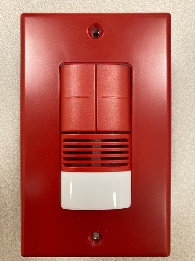
YH9NXSMDT-LH
Jan 24, 2023Wall switch sensors
Equipment Class
DTS - Digital Transmission System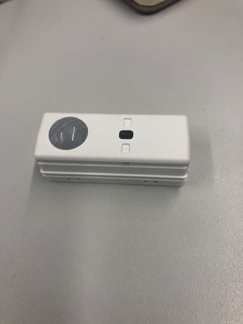
YH9NXSMP2SMI
Aug 28, 2022PIR Occupancy/Daylight Sensor
Equipment Class
DTS - Digital Transmission System