YH9NXSMP2SMIPIR Occupancy/Daylight Sensor
HLI Solutions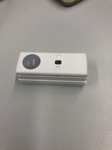
Click to zoom
Application Details
- Equipment Class
- DTS - Digital Transmission System
- Date of Grant
- Aug 28, 2022
- Application Purpose
- Original Equipment
- Date of Application
- Aug 28, 2022
- Equipment Note
- PIR Occupancy/Daylight Sensor
- Frequency Range
- 2402.00000000 - 2480.00000000
- Company
- HLI Solutions
- Country
- United States
Documents & Files
Document Text
Text extracted from the exhibit documents filed with the FCC. Open a document above to read the original.
Users Manual
currentlighting.com © 2022 HLI Solutions, Inc. All rights reserved. Information and specifications subject to change without notice. All values are design or typical values when measured under laboratory conditions. Page 1 of 4 Rev 08/01/22 NXSMP2-SMI_install_sheet_R01 93147263 Rev. A NXSMP2 Series Sensors Slide Mount Sensors SMI INSTALLATION INSTRUCTIONS IMPORTANT SAFEGUARDS READ AND FOLLOW ALL SAFETY INSTRUCTIONS PRECAUTIONS Read and understand all instructions before beginning installation. CAUTION: FOR USE WITH CLASS 2, LOW VOLTAGE SYSTEMS ONLY. DO NOT USE IN HIGH VOLTAGE APPLICATIONS. NOTICE: Class 2 Device, 12-24V, 10mA NOTICE: Suitable for Use in Other Environmental Air Space (Plenums) in Accordance with Section 300.22 (c) of the National Electrical Code. NOTICE: For installation by a licensed electrician in accordance with National and/or Local Electrical Codes and the following instructions. Confirm device ratings are suitable for application prior to installation. Use of this device in applications beyond its specified ratings other than its intended use may cause an unsafe condition and will void manufacturer’s warranty. Use only approved materials and components (i.e. wire nuts, electrical box, etc.) as appropriate for installation. NOTICE: DO NOT INSTALL IF PRODUCT APPEARS TO BE DAMAGED. NOTICE: Do not use outdoors. For In-fixture use only. NOTICE: Do not use this equipment for other than its intended use. REGULATORY INFORMATION 1. Contains Transmitter Module FCC ID: YH9NXSMP2SMI IC: 9044A-NXSMP2SMI 1. This device complies with FCC part 15 Rules. Operation is subject to the following two conditions: This device may not cause harmful inference. 2. This device must accept any interference received, including interference that may cause undesired operation. 2. FCC Interference Statement (Part 15.105(b)): This equipment has been tested and found to comply with the limits for a Class B digital device, pursuant to Part 15 of the FCC Rules. These limits are designed to provide reasonable protection against harmful interference in a residential installation. This equipment generates uses and can radiate radio frequency energy and, if not installed and used in accordance with the instructions, may cause harmful interference to radio communications. However, there is no guarantee that interference will not occur in a particular installation. If this equipment does cause harmful interference to radio or television reception, which can be determined by turning the equipment off and on, the user is encouraged to try to correct the interference by one of the following measures: 1. Reorient or relocate the receiving antenna. 2. Increase the separation between the equipment and receiver 3. Connect the equipment into an outlet on a circuit different from that to which the receiver is connected. 4. Consult the dealer or an experienced radio/TV technician for help. 3. FCC Part 15 Clause 15.21: Changes or modifications not expressly approved by the party responsible for compliance could void the user’s authority to operate the equipment. 4. ISED RSS-Gen Notice This device complies with Industry Canada’s license-exempt RSSs. Operation is subject to the following two conditions: 1. The device may not cause interference; and 2. This device must accept any interference, including interference that may cause undesired operation of the device. Le présent appareil est conforme aux CNR d’Industrie Canada applicables aux appareils radio exempts de licence. L’exploitation est autorisée aux deux conditions suivantes: 1. l’appareil ne doit pas produire de brouillage; 2. l’appareil doit accepter tout brouillage radioélectrique subi, même si le brouillage est susceptible d’en compromettre le fonctionnement. SAVE THESE INSTRUCTIONS AND PROVIDE TO OWNER AFTER INSTALLATION IS COMPLETED currentlighting.com © 2022 HLI Solutions, Inc. All rights reserved. Information and specifications subject to change without notice. All values are design or typical values when measured under laboratory conditions. Page 2 of 4 Rev 08/01/22 NXSMP2-SMI_install_sheet_R01 93147263 Rev. A DESCRIPTION NXSMP2 Series Digital Smart Sensors are a combination PIR Occupancy Sensor and Closed Loop Daylight sensor specifically designed for installation within a lighting fixture and ceiling mount applications. When used with corresponding NXFM2 Series Fixture Module, the NXSMP2 Series Sensors can be programmed to provide Automatic On/Off control based on occupancy and/ or Automatic Light Level Control based on the amount of ambient daylight. The NXSMP2 Series sensors also include a wireless 2.4GHz radio and Integral Bluetooth® for wireless networking and ladder-less programming from a mobile device. The NXSMP2 Series Digital Sensors can be configured via the NX Lighting Controls mobile application and can be utilized in either stand alone or networked applications with other NX Room Control or NX Network devices. IN-FIXTURE INSTALLATION NOTE: The NXSMP2-SMI is designed for a slide mount application into a rectangular opening with specified tolerances in either the fixture housing material or optics. Field installation of the NXSMP2-SMI is not supported or recommended. INSTALLATION FOR IN-FIXTURE DEPLOYMENT 1. Choose a mounting location on the housing or lens where the sensor face and sensor lens will be oriented in the downward position as close to level as possible. NOTE: The sensor should be clear from obstructions to ensure proper detection. 2. Once a position is selected a 2.0”L x 0.7” opening in the housing or lens needs to made in order for the sensor to slide into position using the slots on either side of the sensor housing. NOTE: The NXSMP2-SMI sensor cannot be installed in a material with great than 0.1” thickness. (See Mounting Detail Below for Slot Detail and Material Thickness) 3. After the sensor is mounted locate the miniature 4-pin SmartPORT positioned on the back of the sensor. Using a NXCBL-I or NXCBL-O insert the connector i…
Text truncated - open the document above for the full version.
RF Exposure Info
Project #: 22455-15 Company: Hubblell Control Solutions EUT: NXSMP2-SMI RF Exposure Evaluation Report Prepared for: Hubblell Control Solutions 710 Hesters Crossing Rd., Suite 100 Round Rock, TX 78681 By Nemko PTI, Inc. 1601 North A.W. Grimes Blvd., Suite B Round Rock, Texas 78665 May 26, 2022 Written by Shakil Murad Wireless Engineer 22455-15, NXSMP2-SMI Nemko PTI Page 2 of 6 Table of Contents 1.0 Maximum Permissible Exposure Evaluation (Supplements the test report.) ....................................................... 3 1.1 Applicable Documents .................................................................................................................................... 3 1.2 Criteria ............................................................................................................................................................ 3 1.3 Procedure ........................................................................................................................................................ 3 1.4 Duty Cycle Correction Factor Measurement .................................................................................................. 4 1.5 Power to Exposure Calculation, Conducted .................................................................................................... 5 1.6 RF MPE Evaluation – FCC ............................................................................................................................. 5 1.7 RF MPE Evaluation – ISED Canada............................................................................................................... 6 1.8 Conclusion ...................................................................................................................................................... 6 NOTICE: (1) This Report must not be used to claim product endorsement, by NVLAP, NIST, the FCC or any other Agency. This report also does not warrant certification by NVLAP or NIST. (2) This report shall not be reproduced except in full, without the written approval of Nemko PTI, Inc. (3) The significance of this report is dependent on the representative character of the test sample submitted for evaluation and the results apply only in reference to the sample tested. The manufacturer must continuously implement the changes shown herein to attain and maintain the required degree of compliance. 22455-15, NXSMP2-SMI Nemko PTI Page 3 of 6 1.0 Maximum Permissible Exposure Evaluation (Supplements the test report.) The measured power is considered for the intended use of the device and resulting RF exposure to the user. 1.1 Applicable Documents Table 1.1.1: Applicable Documents Document Title RSS-102 Issue 5 Radio Frequency (RF) Exposure Compliance of Radiocommunication Apparatus (All Frequency Bands) KDB 447498 D01 General RF Exposure Guidance v06 RF EXPOSURE PROCEDURES AND EQUIPMENT AUTHORIZATION POLICIES FOR MOBILE AND PORTABLE DEVICES OET Bulletin 65 Edition 97-01 Evaluating Compliance with FCC Guidelines for Human Exposure to Radiofrequency Electromagnetic Fields 1.2 Criteria Section Reference Test Detail FCC 47 CFR Part 1 I, 1.1310 // RSS-102, Issue 5 Radiofrequency radiation exposure limits 1.3 Procedure Using measurement of peak power and considering the intended application, determine the permissible exposure level, applicability of exclusion, or whether additional exposure tests (SAR) are indicated. When applicable justify conclusion for selected exposure level and separation distance. 22455-15, NXSMP2-SMI Nemko PTI Page 4 of 6 1.4 Duty Cycle Correction Factor Measurement Measurement is based on intervals not to exceed 100 msec. Maximum transmitter on time is divided by the lesser of 100 msec or the actual measured minimum transmitter interval time. The result is converted to dB and applied as needed to peak measurements of transmitter artifacts to determine average power. This is not a pass/fail measurement. Continuous packet transmission mode was used for the duty cycle measurement, which would represent a worst- case operating scenario. On Time (msec) Time Interval (msec) Duty Cycle Factor (dB) (On Time/Interval) Exposure Weighing Factor (dB) (10 * Log 10 (Duty Cycle Factor ) 1.254 1.486 = 0.844 = -0.74 Plotted measurements appear below: Transmit Event TimeTime Interval (Return to channel time) 22455-15, NXSMP2-SMI Nemko PTI Page 5 of 6 1.5 Power to Exposure Calculation, Conducted The EUT transmitter power is determined by conducted measurement. Safe exposure distance was calculated for the allowed maximum uncontrolled public exposure limit. Measured Conducted Peak Power (dBm) Exposure Weighing Factor (dB) Antenna Gain (dBi) Corrected Peak Power EIRP (dBm) EIRP In Linear Terms (mW) 7.85 Not used to get worse case EIRP 3 10.85 12.16 1.6 RF MPE Evaluation – FCC FCC 47 CFR Part 1 I, 1.1310, Radiofrequency radiation exposure limits. According to table above, the MPE limit for 2400 MHz transmitter shall not exceed power density of 1 mW/cm 2 at a distance of 20 cm from the EUT. Calculation: EIRP = 12.16 mW = 0.01216 W Distance = d = 20 cm = 0.2 m Power Density = EIRP/4πd 2 = 0.01216/4*π*(0.2) 2 = 0.024 W/m 2 = 0.0024 mW/cm 2 Power Density 0.0024 mW/cm 2 < 1 mW/cm 2 22455-15, NXSMP2-SMI Nemko PTI Page 6 of 6 1.7 RF MPE Evaluation – ISED Canada RSS-102, Section 2.5.2, Exemption Limits for Routine Evaluation – RF Exposure Evaluation RF exposure evaluation is required if the separation distance between the user and/or bystander and the device’s radiating element is greater than 20 cm, except when the device operates as follows: 1) below 20 MHz 6 and the source-based, time-averaged maximum e.i.r.p. of the device is equal to or less than 1 W (adjusted for tune-up tolerance) 2) at or above 20 MHz and below 48 MHz and the source-based, time-averaged maximum e.i.r.p. of the device is equal to or less than 4.49/ƒ0.5W (adjusted for tune-up tolerance), where ƒ is in MHz 3) at or above 48 MHz and below 300 MHz and the source-based, time…
Text truncated - open the document above for the full version.
Test Report
Project 22455-15 Hubbell Control Solutions NXSMP2-SMI Wireless Test Report Prepared for: Hubbell Control Solutions 710 Hesters Crossing Rd, Suite 100 Round Rock, TX 78681 By Nemko PTI, Inc. 1601 North A.W. Grimes Blvd., Suite B Round Rock, Texas 78665 January 26, 2022 Written by Shakil Murad Wireless Engineer 22455-15, NXSMP2-SMI 22738 Professional Testing (EMI) Inc. Page 2 of 38 Table of Contents Compliance Certificate .................................................................................................................................................. 4 Test Result Summary ..................................................................................................................................................... 5 1.0 Introduction .......................................................................................................................................................... 6 1.1 Scope ............................................................................................................................................................... 6 1.2 EUT Description ............................................................................................................................................. 6 1.3 EUT Test Mode ............................................................................................................................................... 6 1.4 EUT Test Configuration .................................................................................................................................. 6 1.5 Modifications to Equipment ............................................................................................................................ 6 1.6 Test Site .......................................................................................................................................................... 6 1.7 Measurement Corrections ............................................................................................................................... 6 1.8 Applicable Documents .................................................................................................................................... 7 2.0 Fundamental Power ............................................................................................................................................. 8 2.1 Test Procedure ................................................................................................................................................ 8 2.2 Test Criteria .................................................................................................................................................... 8 2.3 Test Results, Peak Power ................................................................................................................................ 8 2.4 Test Results, Duty Cycle ............................................................................................................................... 10 3.0 Power Spectral Density ...................................................................................................................................... 11 3.1 Test Procedure .............................................................................................................................................. 11 3.2 Test Criteria .................................................................................................................................................. 11 3.3 Test Results, Tabular..................................................................................................................................... 12 4.0 Occupied Bandwidth .......................................................................................................................................... 13 4.1 Test Procedure .............................................................................................................................................. 13 4.2 Test Criteria .................................................................................................................................................. 13 4.3 Test Results, Tabular..................................................................................................................................... 13 4.4 Test Plots, Recorded: 6 dB, 99% BW ........................................................................................................... 14 5.0 Band Edge .......................................................................................................................................................... 15 5.1 Test Procedure .............................................................................................................................................. 15 5.2 Test Criteria .................................................................................................................................................. 15 5.3 Test Results ................................................................................................................................................... 15 6.0 Conducted Antenna Port Spurious Emissions, Transmit Mode ......................................................................... 17 6.1 Test Procedure .............................................................................................................................................. 17 6.2 Test Criteria .................................................................................................................................................. 17 6.3 Test Results ................................................................................................................................................... 17 7.0 Transmitter Radiated Spurious Emissions ......................................................................................................... 21 7.1 Test Procedure…
Text truncated - open the document above for the full version.
Contact Information
Applicant
Ryan Belanger
Test Firm
Professional Testing (EMI), Inc.Larry Finn
Technical Specifications
| # | Rule Parts | Frequency Range | Power Output |
|---|---|---|---|
| 1 | 15C | 2.40 GHz - 2.48 GHz | 6.10 mW |
Other Applications from HLI Solutions
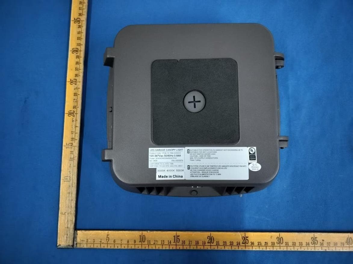
YH9LSCS
Jul 16, 2026LED GARAEG CANOPY
Equipment Class
DXX - Part 15 Low Power Communication Device TransmitterYH9NXSMP3
Sep 04, 2025Low voltage occupancy and daylight sensor with radio and built-in actuators for lighting control
Equipment Class
DTS - Digital Transmission SystemYH9NXOFM2
Sep 08, 2024On-Fixture Module for Lighting Control
Equipment Class
DTS - Digital Transmission System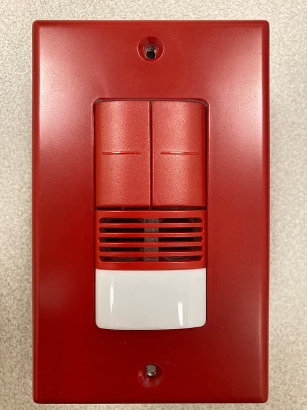
YH9NXSMDT-LH
Jan 24, 2023Wall switch sensors
Equipment Class
DTS - Digital Transmission System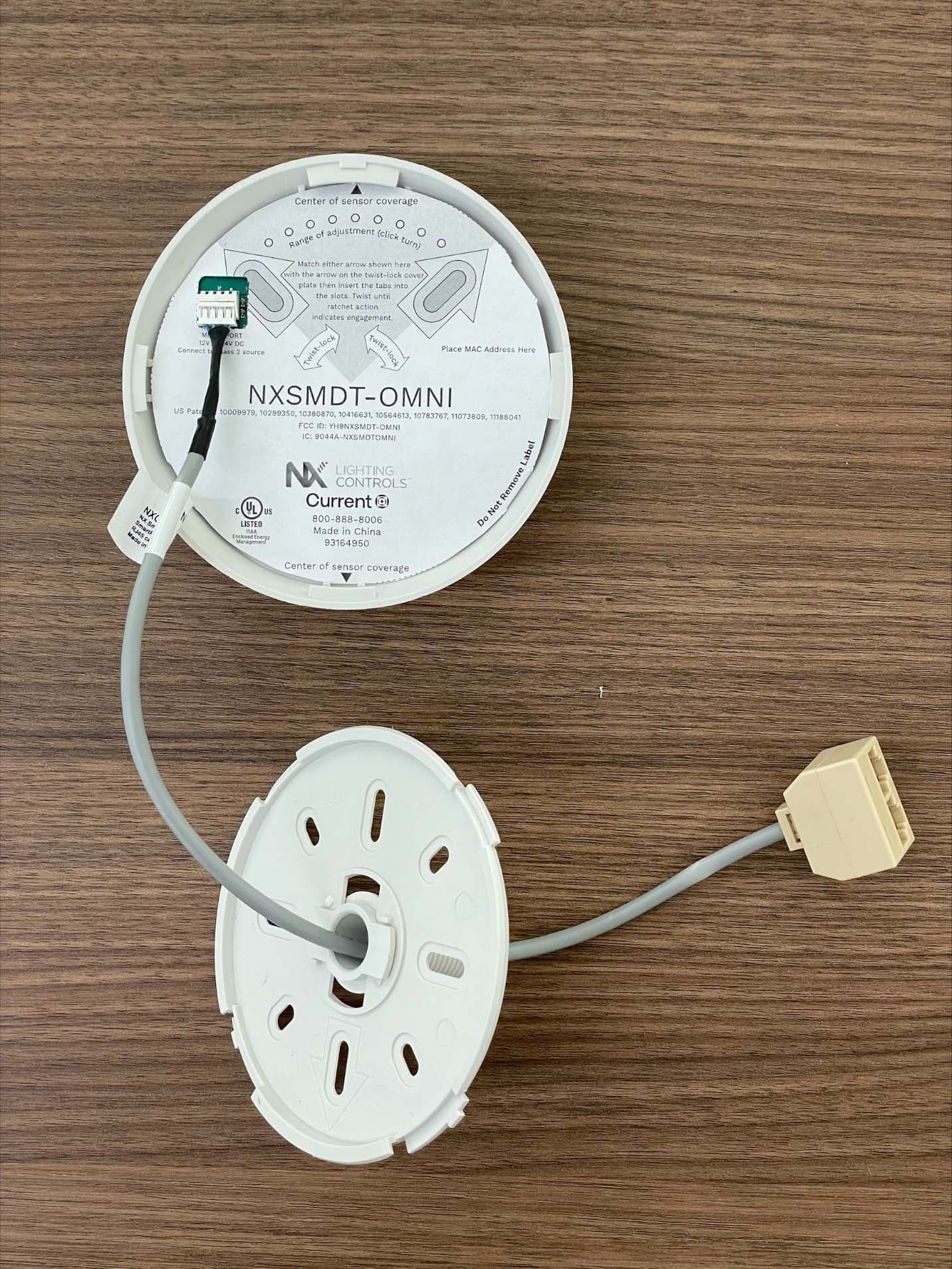
YH9NXSMDT-OMNI
Sep 26, 2022PIR Occupancy/Daylight Sensor
Equipment Class
DTS - Digital Transmission System