YH9NXSWWRSWireless Lighting Control
HLI Solutions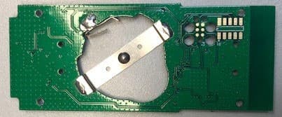
Click to zoom
Application Details
- Equipment Class
- DTS - Digital Transmission System
- Date of Grant
- Jan 11, 2022
- Application Purpose
- Original Equipment
- Date of Application
- Jan 11, 2022
- Equipment Note
- Wireless Lighting Control
- Frequency Range
- 2402.00000000 - 2480.00000000
- Company
- HLI Solutions
- Country
- United States
Documents & Files
Document Text
Text extracted from the exhibit documents filed with the FCC. Open a document above to read the original.
Users Manual
3511B 06152020 72- 00655 ™ PRELIMINARY NX Wireless Rocker Wall Station INSTALLATION INSTRUCTIONS IMPORTANT SAFEGUARDS READ AND FOLLOW ALL SAFETY INSTRUCTIONS PRECAUTIONS Read and understand all instructions before beginning installation. CAUTION: FOR USE WITH CLASS 2, LOW VOLTAGE SYSTEMS ONLY. DO NOT USE IN HIGH VOLTAGE APPLICATIONS. NOTICE: For installation by a licensed electrician in accordance with National and/or Local Electrical Codes and the following instructions. Confirm device ratings are suitable for application prior to installation. Use of this device in applications beyond its specified ratings other than its intended use may cause an unsafe condition and will void manufacturer’s warranty. Use only approved materials and components (i.e. wire nuts, electrical box, etc.) as appropriate for installation. NOTICE: DO NOT INSTALL IF PRODUCT APPEARS TO BE DAMAGED. NOTICE: Do not use outdoors. NOTICE: Do not use this equipment for other than its intended use. NOTICE: The NX Wireless Wall Station uses 1 CR2032 coin cell battery ONLY. Do not use rechargeable battery. Using an improper battery may damage the NX Wireless Wall Station. Please dispose of this battery at a recycling facility. Contact your local waste disposal provider to find a recycling center location nearest you. CAUTION: Risk of explosion if battery is replaced by an incorrect type. Dispose of used batteries according to instructions. REGULATORY INFORMATION • Contains Transmitter Module FCC ID: YH9NXSWWRS IC:9044A-NXSWWRS 1. This device complies with FCC part 15 Rules. Operation is subject to the following two conditions: This device may not cause harmful inference. 2. This device must accept any interference received, including interference that may cause undesired operation. • FCC Interference Statement (Part 15.105(b)): This equipment has been tested and found to comply with the limits for a Class B digital device, pursuant to Part 15 of the FCC Rules. These limits are designed to provide reasonable protection against harmful interference in a residential installation. This equipment generates uses and can radiate radio frequency energy and, if not installed and used in accordance with the instructions, may cause harmful interference to radio communications. However, there is no guarantee that interference will not occur in a particular installation. If this equipment does cause harmful interference to radio or television reception, which can be determined by turning the equipment off and on, the user is encouraged to try to correct the interference by one of the following measures: 1. Reorient or relocate the receiving antenna. 2. Increase the separation between the equipment and receiver 3. Connect the equipment into an outlet on a circuit different from that to which the receiver is connected. 4. Consult the dealer or an experienced radio/TV technician for help. • FCC Part 15 Clause 15.21: Changes or modifications not expressly approved by the party responsible for compliance could void the user’s authority to operate the equipment. • ISED RSS-Gen Notice This device complies with Industry Canada’s license-exempt RSSs. Operation is subject to the following two conditions: 1. The device may not cause interference; and 2. This device must accept any interference, including interference that may cause undesired operation of the device. Le présent appareil est conforme aux CNR d’Industrie Canada applicables aux appareils radio exempts de licence. L’exploitation est autorisée aux deux conditions suivantes: 1. l’appareil ne doit pas produire de brouillage; 2. l’appareil doit accepter tout brouillage radioélectrique subi, même si le brouillage est susceptible d’en compromettre le fonctionnement. SAVE THESE INSTRUCTIONS AND PROVIDE TO OWNER AFTER INSTALLATION IS COMPLETED 701 Millennium Blvd. | Greenville, SC 29607 | (864) 678-1000 | www.hubbellcontrolsolutions.com Copyright © 2020 Hubbell Control Solutions, a division of Hubbell Lighting, Inc. All rights reserved. All product and company names, logos and product identifiers are trademarks ™ or registered trademarks ® of Hubbell Lighting, Inc. or their respective owners. Use of them does not necessarily imply any affiliation with or endorsement by such respective owners. 3511B 06152020 72- 00655 ™ PRELIMINARY MOUNTING • Installed directly into a standard gang box us- ing a standard decora faceplate (not included) • Can be installed using the provided 3M Com- mand™ Strip and Hubbell Controls custom faceplate • Can be installed next to an existing standard gang box using the provided 3M Command™ Strip and multiple station decora faceplate (not included) • Built in level to ensure device is installed perfectly ELECTRICAL Input: • Class 2 Low Voltage • 3VDC. 5.4mA • Powered using CR2032 Battery Only OPERATING ENVIRONMENT • Rated for Indoor Use ONLY • Operating temperature: 32° to 104°F (0° to 40°C) • Relative humidity (non-condensing): 0% to 90% CERTIFICATIONS • Conforms with UL STD 916 and CSA C22.2 No. 205 • FCC Part 15.247 • Contains Transmitter Module FCC ID: YH9NXSWWRS • •Bluetooth® Version 4.1 WARRANTY • 5 year limited warranty • See HLI Standard Warranty for additional information DESCRIPTION Hubbell Control Solutions’ NX Wireless Wall Station provides wireless manual control of the NX System. The NX Wireless Wall Station provides simple ON, RAISE, LOWER, and OFF functionality for NX Devices and NX Enabled Luminaires. The NX Wireless Wall Station can be configured via the controlHUBB mobile application and can be utilized in either stand alone or networked applications with other NX Room Control or NX Network devices. SPECIFICATIONS BAT TE RY I N STALL ATI O N 1. Before using the NX Wireless Rocker Wall Station you will need to first remove the battery tab. 2. Pull the plastic tab out from the back of the product and discard (See Figure 1). 3. The NX Wall Station is now powered and can be installed using one of the three approved methods listed below : WALL MOUNT INS…
Text truncated - open the document above for the full version.
Cover Letter(s)
Date (6/01/2021) Federal Communications Commission Equipment Authorization Branch 7435 Oakland Mills Road Columbia, MD 21046 Confidentiality Request FCC ID: YH9NXSWWRS Pursuant to Sections 0.457(d)(1)(ii) and 0.459 of the Commission’s Rules, Hubbell Control Solutions hereby requests permanent confidential treatment of information accompanying this application as outlined below: Schematics, Bill of Materials, Theory of Operation, Tune-up procedure We, Hubbell Control Solutions, also hereby requests short-term confidential treatment of information accompanying this application as outlined below for a period of period of 180 days: Certification number; Company number; previous certification number (if applicable); Company name; Company contact information (name, address, email, fax, phone; Manufacturer (name, contact person address, email, fax, phone; Model name and/or number as it appears on the product; Specification or standard code and issue number; Type of equipment (equipment category); Test Lab name, address, ID #, OATS filing reference number; Test Lab report number and date; List of accessories with which the equipment was tested; List of operational features; Frequency Range; Emission Designator(s); (Nature of signal(s); Type of information being transmitted; Details about the signal(s); Nature of multiplexing ;) Bandwidth(s); Type of modulation(s); Field strength measured in microvolt per meter @ 3 meters if the antenna is integral to the device or conducted RF Power if the antenna is detachable; and Gain of antenna(s) the device was certified with. The above materials contain trade secrets and proprietary information not customarily released to the public. The public disclosure of these matters might be harmful to the Applicant and provide unjustified benefits to its competitors. The Applicant understands that pursuant to Rule 0.457(d)(1)(ii), disclosure of this Application and all accompanying materials will not be made before the date of the Grant for this Application. Yours sincerely, Name: Eric Weber Title: Director of System Architecture
External Photos
21589 External Photos Page 1 of 3 Side 1 of 6 ‐ Front Side 2 ‐ Bottom Side 3 Side 4 Side 5 Side 6 ‐ Top ***
ID Label/Location Info
FCC: YH9NXSWWRS IC: 9044A-NXSWWRS ENCLOSED ENERGY MGMT E174097 Model: NXSW-WRS-WH
Internal Photos
21589 Internal Photos Page 1 of 1 Front Back ***
RF Exposure Info
21589 Hubbell Control Solutions Page 1 of 3 Professional Testing (EMI) Inc. 1601 North A.W. Grimes Blvd., Suite B Round Rock, TX 78665 e-mail: [email protected] (512) 244-3371 Fax: (512) 244-1846 1.0 Maximum Permissible Exposure Evaluation (Supplements the test report.) The measured power is considered for the intended use of the device and resulting RF exposure to the user. 1.2 Criteria Section Reference Date 447498 D01 General RF Exposure Guidance v06 // RSS-102 Issue 5 21 Sep 2021 1.3 Procedure Using measurement of peak power and considering the intended application, determine the permissible exposure level, applicability of exclusion, or whether additional exposure tests (SAR) are indicated. When applicable justify conclusion for selected exposure level and separation distance. The NXSW-WRS-WH is a wall mounted rocker switch designed to control lighting systems. The device features an integrated 2.4GHz BLE radio. The device features several buttons with which the user may control various lighting functions. Typically, the user will use their fingers to actuate the buttons for brief moments. Some features require holding the buttons down for at least 10 seconds. No other parts of the body are expected to contact the switch. Due to the direct contact with user limbs (hands), exposure distance will be set at 5mm from the user limbs as radio is internal to the device separated from the user by the plastic housing. Exposure to head/trunk will be >20cm. Adjustment is infrequent and is usually done by using the intended wireless feature remotely from a smartphone with no contact with actual device. Duty Cycle was measured on the device using a continuous packet transmission mode (worst-case), which resulted in a Duty Cycle correction factor of -0.78 dB. Duty Cycle Correction Factor Measurement: Measurement is based on intervals not to exceed 100 msec. Maximum transmitter on time is divided by the lesser of 100 msec or the actual measured minimum transmitter interval time. The result is converted to dB and applied as needed to peak measurements of transmitter harmonics to determine average power. This is not a pass/fail measurement. 21589 Hubbell Control Solutions Page 2 of 3 Professional Testing (EMI) Inc. Transmit time: 1.244 ms Period: 1.485 ms DC = 1.244 / 1.485 = 0.8377 = 83.77 % Weighting factor for exposure: 10 log (0.8377) = -0.78 dB 1.4 Power to Exposure Calculation For 2.4 GHz radio power is determined by conducted measurement. Safe exposure distance was calculated for the allowed maximum uncontrolled public exposure limit. Table 1.4.1 Power Calculation for Exposure, 2.4 GHz Radio (Highest frequency 2.480 GHz) Measured Radiated Peak Power (EIRP) dBm Source Duty Cycle Factor dB Antenna Gain 1 dBi Calculated EIRP dBm EIRP In Linear Terms mW 8.4 -0.78 N/A 7.62 5.78 1 Peak power was measured radiated, so the antenna gain was included in the measurement. 21589 Hubbell Control Solutions Page 3 of 3 Professional Testing (EMI) Inc. 1.5 SAR Exemption Calculation – FCC Applicable requirement: KDB 447498 Clause 4.3.1 Section 1 Calculated power (max power including tune up tolerance = 5.78 mW): [(5.78 mW)/(5 mm)] · [√2.4 (GHz)] = 1.79 1.79 ≤ 6.0 (Limb exposure) 1.79 ≤ 3.0 (Non-Limb exposure) 1.6 SAR Exemption Calculation – IC Applying Table 1 of RSS-102 Clause 2.5.1 using 0.5 cm or 5 mm spacing column and row 2450 MHz. The exemption limit is 4 mW. Since the exposure is to the limbs (hand in this case), the exposure allowance is multiplied by 2.5, yielding an exemption limit of 10mW. 5.78 mW < 10 mW for limb exposure 1.7 Conclusion The exposure limit is satisfied. Signed: Larry Finn ***
Test Report
Project 21589-15 Hubbell Control Solutions NX Wireless Rocker Switch (Model NXSW-WRS-WH) Wireless Certification Report Prepared for: Hubbell Control Solutions 710 Hesters Crossing Road Suite 100 Round Rock, TX 78681 By Professional Testing (EMI), Inc. 1601 North A.W. Grimes Blvd., Suite B Round Rock, Texas 78665 11 Nov 2021 Reviewed by Written by Shakil Murad Lead EMC Engineer Eric Lifsey EMC Engineer Hubbell Control Solutions – NX Wireless Rocker Switch 21589 Professional Testing (EMI) Inc. Page 2 of 45 Revision History Revision Number Description Date Draft 01 For review. 10 Apr 2020 Final 01 Final release 21 Sep 2021 Final 02 Added peak power plots; corrected tabular peak power; minor corrections 11 Nov 2021 Errata: None. Hubbell Control Solutions – NX Wireless Rocker Switch 21589 Professional Testing (EMI) Inc. Page 3 of 45 Table of C ontents Revision History ............................................................................................................................................................. 2 Certificate of Compliance ............................................................................................................................................. 5 1.0 Introduction .......................................................................................................................................................... 6 1.1 Scope ............................................................................................................................................................... 6 1.2 EUT Description ............................................................................................................................................. 6 1.3 EUT Operation ................................................................................................................................................ 6 1.4 Modifications to Equipment ............................................................................................................................ 6 1.5 Test Site .......................................................................................................................................................... 6 1.6 Radiated Measurements .................................................................................................................................. 7 1.7 Applicable Documents and Clauses ................................................................................................................ 7 2.0 Fundamental Power and Duty Cycle.................................................................................................................... 8 2.1 Test Procedure ................................................................................................................................................ 8 2.2 Test Criteria .................................................................................................................................................... 8 2.3 Test Summary, Peak Power ............................................................................................................................ 8 2.4 Test Results, Peak Power ................................................................................................................................ 9 2.5 Test Results, Duty Cycle ............................................................................................................................... 12 3.0 Power Spectral Density ...................................................................................................................................... 13 3.1 Test Procedure .............................................................................................................................................. 13 3.2 Test Criteria .................................................................................................................................................. 13 3.3 Test Results ................................................................................................................................................... 13 4.0 Occupied Bandwidth .......................................................................................................................................... 15 4.1 Test Procedure .............................................................................................................................................. 15 4.2 Test Criteria .................................................................................................................................................. 15 4.3 Test Results ................................................................................................................................................... 15 4.3.1 Bandwidth Plots, 6 dB ......................................................................................................................... 16 4.3.2 Bandwidth Plots, OBW 99% ............................................................................................................... 17 5.0 Band Edge .......................................................................................................................................................... 18 5.1 Test Procedure .............................................................................................................................................. 18 5.2 Test Criteria .................................................................................................................................................. 18 5.3 Test Results ................................................................................................................................................... 18 5.3.1 Bottom Channel Band Edge ................................................................................................................ 19 5.3.2 Top Channel Band Edge ..................................…
Text truncated - open the document above for the full version.
Test Setup Photos
21589 NXSW-WRS-WH Setup Photos Page 1 of 3 Radiated Output Power Radiated Output Power, Spurious Emissions to 18GHz 21589 NXSW-WRS-WH Setup Photos Page 2 of 3 Radiated Emissions to 1 GHz Spurious Emissions to 26.5GHz 21589 NXSW-WRS-WH Setup Photos Page 3 of 3 Receiver Spurious Emissions ***
Contact Information
Applicant
Ryan Belanger
Test Firm
Professional Testing (EMI), Inc.Larry Finn
Technical Specifications
| # | Rule Parts | Frequency Range | Power Output |
|---|---|---|---|
| 1 | 15C | 2.40 GHz - 2.48 GHz | 7.00 mW |
Other Applications from HLI Solutions
YH9LSCS
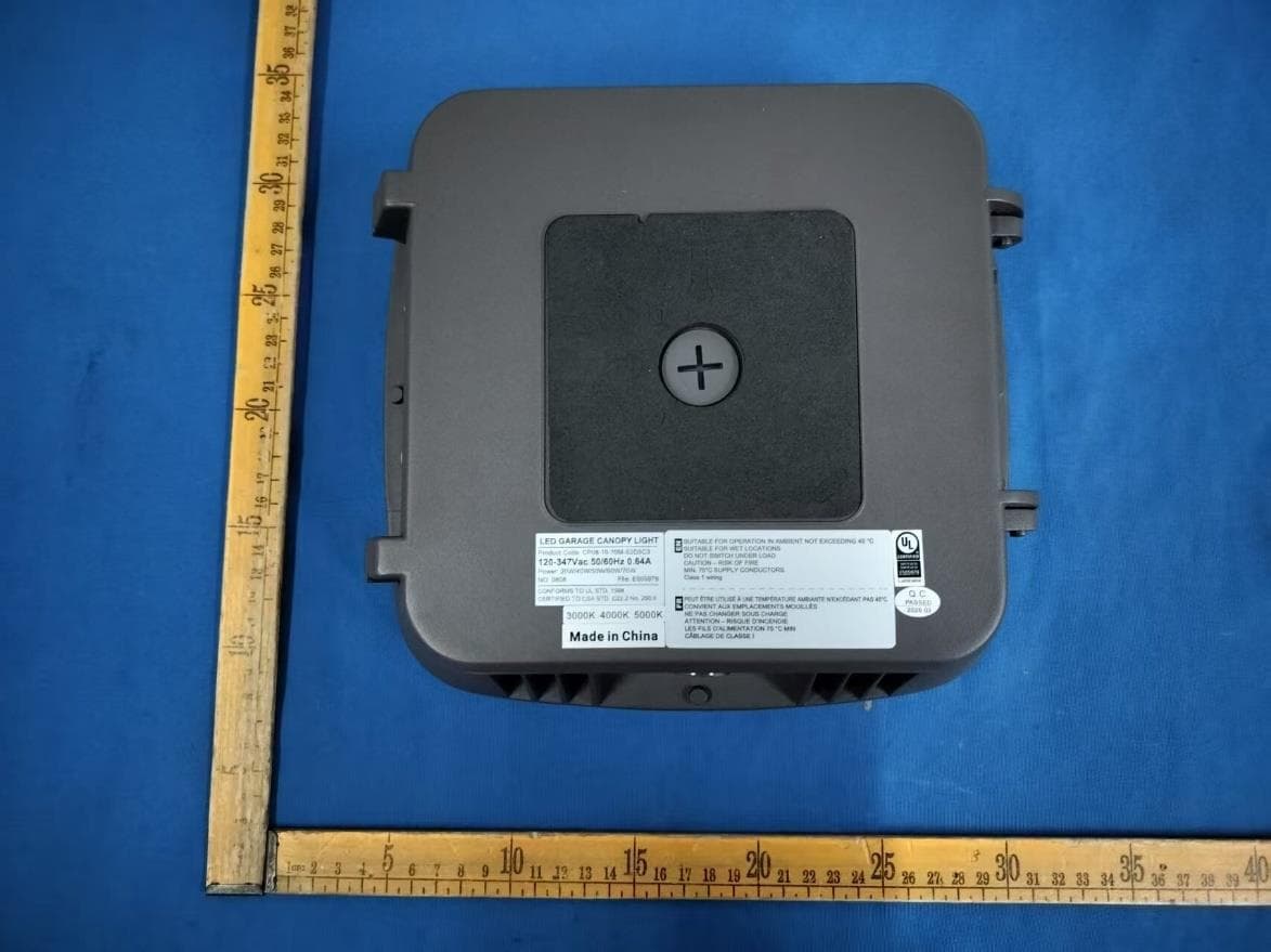
Jul 16, 2026LED GARAEG CANOPY
Equipment Class
DXX - Part 15 Low Power Communication Device TransmitterYH9NXSMP3
Sep 04, 2025Low voltage occupancy and daylight sensor with radio and built-in actuators for lighting control
Equipment Class
DTS - Digital Transmission SystemYH9NXOFM2
Sep 08, 2024On-Fixture Module for Lighting Control
Equipment Class
DTS - Digital Transmission System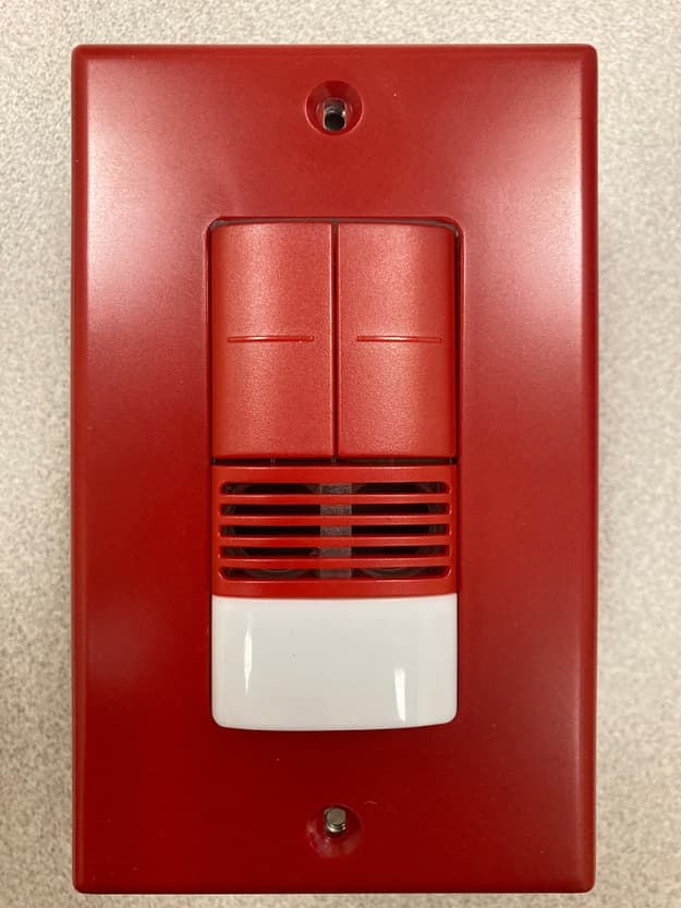
YH9NXSMDT-LH
Jan 24, 2023Wall switch sensors
Equipment Class
DTS - Digital Transmission System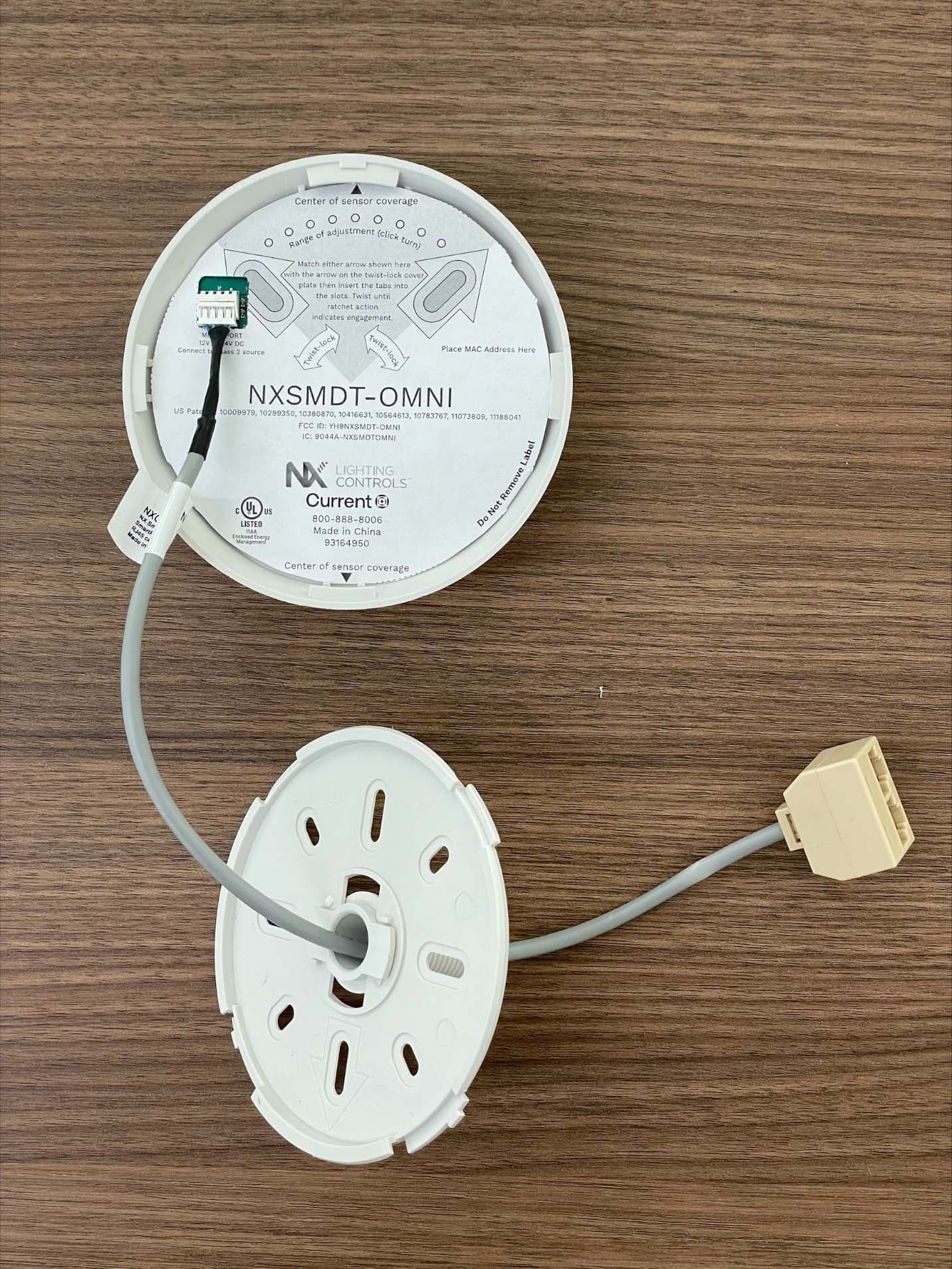
YH9NXSMDT-OMNI
Sep 26, 2022PIR Occupancy/Daylight Sensor
Equipment Class
DTS - Digital Transmission System