YHI-V10001Link Box
NEXCOM international Co.,LTD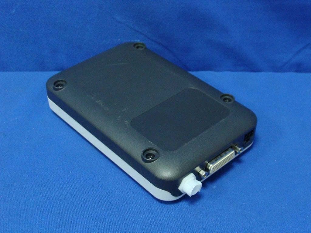
Click to zoom
Application Details
- Equipment Class
- DTS - Digital Transmission System
- Date of Grant
- Dec 07, 2011
- Application Purpose
- Original Equipment
- Date of Application
- Dec 01, 2011
- Equipment Note
- Link Box
- Frequency Range
- 2412.00000000 - 2462.00000000
- Company
- NEXCOM international Co.,LTD
- Country
- Taiwan
Documents & Files
Document Text
Text extracted from the exhibit documents filed with the FCC. Open a document above to read the original.
Users Manual
LAERDAL MEDICAL AS Link Box – Quick-Setup-Guide 1 / 7 Link Box Quick-Setup-Guide 2011-October-17 LAERDAL MEDICAL AS Link Box – Quick-Setup-Guide 2 / 7 CONTENT DESCRIPTION AND SYSTEM SETUP ............................................................................ 3 SAFETY INSTRUCTIONS ............................................................................................. 3 User Environment .................................................................................................... 3 Power Connection and Hazardous Voltage ................................................................... 4 Servicing ................................................................................................................ 4 Accessories ............................................................................................................. 4 SET UP YOUR SIMULATOR WITH LINK BOX ............................................................... 5 Connect Link Box to simulator ................................................................................... 5 Connect blood pressure tube to Link Box ..................................................................... 5 Power the Link Box .................................................................................................. 6 Connect Link Box with other accessories as needed ...................................................... 6 START-UP .................................................................................................................. 6 SHUT-DOWN .............................................................................................................. 6 UPDATES ................................................................................................................... 6 FCC STATEMENT ........................................................................................................ 7 CANADIAN ICES-003 STATEMENT .............................................................................. 7 CE COMPLIANCE STATEMENT ..................................................................................... 7 LAERDAL MEDICAL AS Link Box – Quick-Setup-Guide 3 / 7 DESCRIPTION AND SYSTEM SETUP The Link Box is a vital signs simulation unit. Connected to an applicable medical training simulator, like Nursing Anne or ALS Simulator, the Link Box provides different physiological parameters to the simulator. The Link Box replaces the existing Laerdal VitalSim Vital Signs Simulator. The Link Box may be operated by the remote control SimPad. With the system you are able to perform medical simulations, preparing yourselves for real-life situations. SAFETY INSTRUCTIONS For your protection please, read these safety instructions completely before you connect the equipment to the power source. Carefully observe all warnings, precautions and instructions both on the apparatus and in these operating instructions. Retain this manual for future reference. User Environment Protection against dust and moisture according to IP 22. Do not use this product at altitudes higher than 3000m asl. Do not use the product in ambient temperatures above 35 °C (95°F) and below 0°C (32°F).Relative humidity (RH) must be between 10% to 90%. Water and Moisture Do not operate the apparatus under or near water—for example near a bathtub, kitchen sink, or laundry tub, in a wet basement, near a swimming pool or in other areas with high humidity. Never install jacks for communication cables in wet locations. Do not operate the product with wet hands. Cleaning Unplug the apparatus from communication lines, mains power outlet or any power source before cleaning or polishing. Do not use liquid cleaners or aerosol cleaners. Use a lint-free cloth lightly moistened with water for cleaning the exterior of the apparatus. Lightning Never use this apparatus, or connect/disconnect communication cables or power cables during lightning storms. Dust Do not operate the apparatus in areas with a high concentration of dust. LAERDAL MEDICAL AS Link Box – Quick-Setup-Guide 4 / 7 Power Connection and Hazardous Voltage The product or its accessories may have a hazardous voltage inside. Never attempt to open this product, or any peripherals connected to the product, where this action requires a tool. This product should always be powered from an earthed power outlet In case any parts of the product has visual damage, never attempt to connect main power, or any other power source, before consulting service personnel Route the power cord so as to avoid it being walked on or pinched by items placed upon or against it. Pay particular attention to the plugs, receptacles and the point where the cord exits from the apparatus. Do not tug the power cord. If the provided plug does not fit into your outlet, consult an electrician. Servicing Do not attempt to service the apparatus yourself because opening or removing covers may expose you to dangerous voltages or other hazards, and will void the warranty. Refer all servicing to qualified service personnel. Accessories Use only accessories specified by the manufacturer, or sold with the apparatus. LAERDAL MEDICAL AS Link Box – Quick-Setup-Guide 5 / 7 SET UP YOUR SIMULATOR WITH LINK BOX Connect Link Box to simulator Connect the simulator cable, supplied with the Link Box, to Link Box itself and the simulator. The position where it connects to the simulator to simulator will vary from simulator to simulator. Connect blood pressure tube to Link Box Connect the transparent tube from the simulator, if such equipped, to the white blood pressure connector on the Link Box. LAERDAL MEDICAL AS Link Box – Quick-Setup-Guide 6 / 7 Power the Link Box To mains using AC/DC adapter The Link Box must be powered from the mains using the supplied AC/DC adaptor. Connect Link Box with other accessories as needed CPRmeter USB accessories Audio input – line in Audio output – line out START-UP 1. Make sure the simulator cable, a…
Text truncated - open the document above for the full version.
Cover Letter(s)
Report No. 119320R-RFUSP24V02 Page : 1 of 23 Test Report Product Name Link Box Model No 200-30250 FCC ID. DoC Applicant NEXCOM International Co., LTD Address 15F, No.920, Chung-Cheng Rd.,Zhonghe Dist., New Taipei City 235, Taiwan. Date of Receipt Sep. 16, 2011 Issue Date Oct. 25, 2011 Report No. 119320R-RFUSP24V02 Report Version V1.0 The test results relate only to the samples tested. The test report shall not be reproduced except in full without the written approval of QuieTek Corporation. This report must not be used to claim product endorsement by NVLAP any agency of the U.S. Government Report No. 119320R-RFUSP24V02 Page : 2 of 23 Test Report Certification Issue Date: Oct. 25, 2011 Report No.: 119320R-RFUSP24V02 Product Name Link Box Applicant NEXCOM International Co., LTD Address 15F, No.920, Chung-Cheng Rd.,Zhonghe Dist., New Taipei City 235, Taiwan. Manufacturer NEXCOM International Co., LTD Model No. 200-30250 FCC ID. DoC EUT Rated Voltage DC 12V EUT Test Voltage AC 120V/60Hz Trade Name LAERDAL Applicable Standard FCC CFR Title 47 Part 15 Subpart B: 2010 ANSI C63.4: 2009 Test Result Complied The test results relate only to the samples tested. The test report shall not be reproduced except in full without the written approval of QuieTek Corporation. This report must not be used to claim product endorsement by NVLAP any agency of the U.S. Government Documented By : ( Senior Adm. Specialist / Jinn Chen ) Tested By : ( Assistant Engineer / Henk Huang ) Approved By : ( Manager / Vincent Lin ) Accredited by NIST (NVLAP) NVLAP Lab Code: 200533-0 Report No. 119320R-RFUSP24V02 Page : 3 of 23 TABLE OF CONTENTS Description Page 1. GENERAL INFORMATION .....................................................................................................4 1.1. EUT Description............................................................................................................................4 1.2. Tested System Details....................................................................................................................6 1.3. Configuration of Tested System ....................................................................................................7 1.4. EUT Exercise Software .................................................................................................................7 1.5. Test Facility ...................................................................................................................................8 2. Conducted Emission....................................................................................................................9 2.1. Test Equipment..............................................................................................................................9 2.2. Test Setup ......................................................................................................................................9 2.3. Limits ..........................................................................................................................................10 2.4. Test Procedure .............................................................................................................................10 2.5. Uncertainty ..................................................................................................................................10 2.6. Test Result of Conducted Emission.............................................................................................11 3. Radiated Emission .....................................................................................................................13 3.1. Test Equipment............................................................................................................................13 3.2. Test Setup ....................................................................................................................................14 3.3. Limits ..........................................................................................................................................15 3.4. Test Procedure .............................................................................................................................15 3.5. Uncertainty ..................................................................................................................................16 3.6. Test Result of Radiated Emission................................................................................................17 4. EMI Reduction Method During Compliance Testing ............................................................21 Attachment 1: EUT Test Photographs Attachment 2: EUT Detailed Photographs Report No. 119320R-RFUSP24V02 Page : 4 of 23 1. GENERAL INFORMATION 1.1. EUT Description Product Name Link Box Trade Name LAERDAL Model No. 200-30250 FCC ID. DoC Frequency Range 2412-2462MHz for 802.11b/g Number of Channels 802.11b/g: 11 Data Speed 802.11b: 1-11Mbps, 802.11g: 6-54Mbps Type of Modulation 802.11b:DSSS (DBPSK, DQPSK, CCK) 802.11g:OFDM (BPSK, QPSK, 16QAM, 64QAM) An t en n a Ty pe P I FA Antenna Gain Refer to the table “Antenna List” Channel Control Auto Power Adapter MFR: FSP, M/N: FSP040-DGAA1 Input: AC 100-240V~1.3A, 50-60Hz Output: DC 12.0V, 3.33A MAX (40W MAX) Cable Out: Non-shielded, 1.5m, with one ferrite core bonded. Antenna List No. Manufacturer Model No. Peak Gain 1 SpeedTech DPLP12R-00001-H 1.82 dBi for 2.4GHz Note: The antenna of EUT is conform to FCC 15.203. Report No. 119320R-RFUSP24V02 Page : 5 of 23 802.11b/g Center Frequency of Each Channel: Channel Frequency Channel FrequencyChannel FrequencyChannel Frequency Channel 01: 2412 MHz Channel 02: 2417 MHz Channel 03: 2422 MHz Channel 04: 2427 MHz Channel 05: 2432 MHz Channel 06: 2437 MHz Channel 07: 2442 MHz Channel 08: 2447 MHz Channel 09: 2452 MHz Channel 10: 2457 MHz Channel 11: 2462 MHz Note: 1. The EUT is a Link Box with a built-in 2.4GHz WLAN transceiver. 2. Regard…
Text truncated - open the document above for the full version.
External Photos
Report No.: 119320R-RFUSP42V01 Page : 1 of 17 Attachment 2 : EUT Detailed Photographs (1) EUT Photo (2) EUT Photo
ID Label/Location Info
NEXCOM International Co., LTD FCC ID.: YHI-V10001 15F, No.920, Chung-Cheng Rd.,Zhonghe Dist., New Taipei City 235, Taiwan. Tel : 886-2-82280506 FCC ID Label The FCC ID Label will be placed on the equipment as shown in the photograph below.
ID Label/Location Info
NEXCOM International Co., LTD FCC ID.: YHI-V10001 15F, No.920, Chung-Cheng Rd.,Zhonghe Dist., New Taipei City 235, Taiwan. Tel : 886-2-82280506 FCC ID Label The FCC ID Label will be placed on the equipment as shown in the photograph below.
Internal Photos
Report No.: 119320R-RFUSP42V01 Page : 2 of 17 (3) EUT Photo (4) EUT Photo Report No.: 119320R-RFUSP42V01 Page : 3 of 17 (5) EUT Photo (6) EUT Photo Report No.: 119320R-RFUSP42V01 Page : 4 of 17 (7) EUT Photo (8) EUT Photo Report No.: 119320R-RFUSP42V01 Page : 5 of 17 (9) EUT Photo (10) EUT Photo Report No.: 119320R-RFUSP42V01 Page : 6 of 17 (11) EUT Photo (12) EUT Photo Report No.: 119320R-RFUSP42V01 Page : 7 of 17 (13) EUT Photo (14) EUT Photo Report No.: 119320R-RFUSP42V01 Page : 8 of 17 (15) EUT Photo (16) EUT Photo Report No.: 119320R-RFUSP42V01 Page : 9 of 17 (17) EUT Photo (18) EUT Photo Report No.: 119320R-RFUSP42V01 Page : 10 of 17 (19) EUT Photo (20) EUT Photo Report No.: 119320R-RFUSP42V01 Page : 11 of 17 (21) EUT Photo (22) EUT Photo Report No.: 119320R-RFUSP42V01 Page : 12 of 17 (23) EUT Photo (24) EUT Photo Report No.: 119320R-RFUSP42V01 Page : 13 of 17 (25) EUT Photo (26) EUT Photo Report No.: 119320R-RFUSP42V01 Page : 14 of 17 (27) EUT Photo (28) EUT Photo Report No.: 119320R-RFUSP42V01 Page : 15 of 17 (29) EUT Photo (30) EUT Photo Report No.: 119320R-RFUSP42V01 Page : 16 of 17 (31) EUT Photo (32) EUT Photo Report No.: 119320R-RFUSP42V01 Page : 17 of 17 (33) EUT Photo
Operational Description
Report No. 119320R-RFUSP42V01 Page : 7 of 71 1.2. Operational Description The EUT is a Link Box, This device provided four kinds of transmitting speed 1, 2, 5.5 and 11Mbps and the device of RF carrier is DBPSK, DQPSK and CCK (IEEE 802.11b). The device provided of eight kinds of transmitting speed 6, 9, 12, 18, 24, 36, 48 and 54Mbps the device of RF carrier is BPSK, QPSK, 16QAM and 64QAM (IEEE 802.11g). This Link Box, compliant with IEEE 802.11b and IEEE 802.11g, is a high-efficiency Wireless LAN adapter. It allows your computer to connect to a wireless network and to share resources, such as files or printers without being bound to the network wires. Operation in 2.4GHz Direst Sequence Spread Spectrum (DSSS) and Orthogonal Frequency Division Multiplexing (OFDM) radio transmission, the Link Box Wired Equivalent Protection (WEP) algorithm is used. In addition, its standard compliance ensures that it can communicate with any IEEE 802.11b and IEEE 802.11g network. Mode 1: Transmit (802.11b 1Mbps) Test Mode: Mode 2: Transmit (802.11g 6Mbps)
RF Exposure Info
Report No. 119320R-RFUSP42V01 Page: 1 of 3 RF Exposure Evaluation declaration Product Name Link Box Model No. 200-30250 FCC ID YHI-V10001 Applicant NEXCOM International Co., LTD Address 15F, No.920, Chung-Cheng Rd.,Zhonghe Dist., New Taipei City 235, Taiwan. Date of Receipt Sep. 16, 2011 Date of Declaration Nov. 01, 2011 Report No. 119320R-RFUSP42V01 The declaration results relate only to the samples calculated. The declaration shall not be reproduced except in full without the written approval of QuieTek Corporation. This report must not be used to claim product endorsement by NVLAP any agency of the U.S. Government Report No. 119320R-RFUSP42V01 Page: 2 of 3 1. RF Exposure Evaluation 1.1. Limits According to FCC 1.1310: The criteria listed in the following table shall be used to evaluate the environment impact of human exposure to radio frequency (RF) radiation as specified in 1.1307(b) LIMITS FOR MAXIMUM PERMISSIBLE EXPOSURE (MPE) Frequency Range (MHz) Electric Field Strength (V/m) Magnetic Field Strength (A/m) Power Density (mW/cm 2 ) Average Time (Minutes) (A) Limits for Occupational/ Control Exposures 300-1500 -- -- F/300 6 1500-100,000 -- -- 5 6 (B) Limits for General Population/ Uncontrolled Exposures 300-1500 -- -- F/1500 6 1500-100,000 -- -- 1 30 F= Frequency in MHz Friis Formula Friis transmission formula: Pd = (Pout*G)/(4*pi*r 2 ) Where Pd = power density in mW/cm 2 Pout = output power to antenna in mW G = gain of antenna in linear scale Pi = 3.1416 R = distance between observation point and center of the radiator in cm Pd id the limit of MPE, 1 mW/cm 2 . If we know the maximum gain of the antenna and the total power input to the antenna, through the calculation, we will know the distance r where the MPE limit is reached. 1.2. Test Procedure Software provided by client enabled the EUT to transmit and receive data at lowest, middle and highest channel individually. The temperature and related humidity: 18°Cand 78% RH. Report No. 119320R-RFUSP42V01 Page: 3 of 3 1.3. Test Result of RF Exposure Evaluation Product : Link Box Test Item : RF Exposure Evaluation Test Site : No.3 OATS External Antenna Gain Antenna Gain: The maximum Gain measured in fully anechoic chamber is 2 dBi in logarithm scale. 802.11b Output Power Into Antenna & RF Exposure Evaluation Distance (1.82 dBi): Channel Frequency (MHz) Output Power to Antenna (mW) Power Density at R = 20 cm (mW/cm2) 1 2412.00 23.2274 0.007026 6 2437.00 27.9898 0.008467 11 2462.00 35.2371 0.010659 802.11g Output Power Into Antenna & RF Exposure Evaluation Distance (1.82 dBi): Channel Frequency (MHz) Output Power to Antenna (mW) Power Density at R = 20 cm (mW/cm2) 1 2412.00 49.6592 0.015022 6 2437.00 51.8800 0.015694 11 2462.00 73.9605 0.022373 The distance r (4 th column) calculated from the Fries transmission formula is far shorter than 20 cm separation requirement.
Test Report
Report No. 119320R-RFUSP42V01 Page : 1 of 71 Test Report Product Name Link Box Model No 200-30250 FCC ID. YHI-V10001 Applicant NEXCOM International Co., LTD Address 15F, No.920, Chung-Cheng Rd.,Zhonghe Dist., New Taipei City 235, Taiwan. Date of Receipt Sep. 16, 2011 Issue Date Oct. 25, 2011 Report No. 119320R-RFUSP42V01 Report Version V1.0 The test results relate only to the samples tested. The test report shall not be reproduced except in full without the written approval of QuieTek Corporation. This report must not be used to claim product endorsement by NVLAP any agency of the U.S. Government Report No. 119320R-RFUSP42V01 Page : 2 of 71 Test Report Certification Issue Date: Oct. 25, 2011 Report No.: 119320R-RFUSP42V01 Product Name Link Box Applicant NEXCOM International Co., LTD Address 15F, No.920, Chung-Cheng Rd.,Zhonghe Dist., New Taipei City 235, Taiwan. Manufacturer NEXCOM International Co., LTD Model No. 200-30250 FCC ID. YHI-V10001 EUT Rated Voltage DC 12V EUT Test Voltage AC 120V/60Hz Trade Name LAERDAL Applicable Standard FCC CFR Title 47 Part 15 Subpart C: 2010 ANSI C63.4: 2009 Test Result Complied The test results relate only to the samples tested. The test report shall not be reproduced except in full without the written approval of QuieTek Corporation. This report must not be used to claim product endorsement by NVLAP any agency of the U.S. Government Documented By : ( Senior Adm. Specialist / Jinn Chen ) Tested By : ( Assistant Engineer / Henk Huang ) Approved By : ( Manager / Vincent Lin ) Accredited by NIST (NVLAP) NVLAP Lab Code: 200533-0 Report No. 119320R-RFUSP42V01 Page : 3 of 71 TABLE OF CONTENTS Description Page 1. GENERAL INFORMATION .....................................................................................................5 1.1. EUT Description............................................................................................................................5 1.2. Operational Description ................................................................................................................7 1.3. Tested System Details....................................................................................................................8 1.4. Configuration of Tested System ....................................................................................................8 1.5. EUT Exercise Software .................................................................................................................9 1.6. Test Facility .................................................................................................................................10 2. Conducted Emission.................................................................................................................. 11 2.1. Test Equipment............................................................................................................................11 2.2. Test Setup ....................................................................................................................................11 2.3. Limits ..........................................................................................................................................12 2.4. Test Procedure .............................................................................................................................12 2.5. Uncertainty ..................................................................................................................................12 2.6. Test Result of Conducted Emission.............................................................................................13 3. Peak Power Output ...................................................................................................................15 3.1. Test Equipment............................................................................................................................15 3.2. Test Setup ....................................................................................................................................15 3.3. Limits ..........................................................................................................................................15 3.4. Test Procedure .............................................................................................................................15 3.5. Uncertainty ..................................................................................................................................15 3.6. Test Result of Peak Power Output...............................................................................................16 4. Radiated Emission .....................................................................................................................18 4.1. Test Equipment............................................................................................................................18 4.2. Test Setup ....................................................................................................................................19 4.3. Limits ..........................................................................................................................................20 4.4. Test Procedure .............................................................................................................................21 4.5. Uncertainty ..................................................................................................................................21 4.6. Test Result of Radiated Emission................................................................................................22 5. RF antenna conducted test........................................................................................................30 5.1. Test Equipment..........................................................................................................................…
Text truncated - open the document above for the full version.
Test Report
Report No. 119320R-RFUSP42V01 Page: 60 of 71 Product : Link Box Test Item : Occupied Bandwidth Data Test Site : No.3 OATS Test Mode : Mode 2: Transmit (802.11g 6Mbps) (2437MHz) Channel No. Frequency (MHz) Measurement Level (kHz) Required Limit (kHz) Result 6 2437 16650 >500 Pass Figure Channel 6: Report No. 119320R-RFUSP42V01 Page: 61 of 71 Product : Link Box Test Item : Occupied Bandwidth Data Test Site : No.3 OATS Test Mode : Mode 2: Transmit (802.11g 6Mbps) (2462MHz) Channel No. Frequency (MHz) Measurement Level (kHz) Required Limit (kHz) Result 11 2462 16650 >500 Pass Figure Channel 11: Report No. 119320R-RFUSP42V01 Page: 62 of 71 8. Power Density 8.1. Test Equipment Equipment Manufacturer Model No./Serial No. Last Cal. Spectrum Analyzer R&S FSP40 / 100170 Jun, 2011 Spectrum Analyzer Agilent E4407B / US39440758 Jun, 2011 X Spectrum Analyzer Agilent N9010A / MY48030495 Apr., 2011 Note: 1. All equipments are calibrated with traceable calibrations. Each calibration is traceable to the national or international standards. 2. The test instruments marked with “X” are used to measure the final test results. 8.2. Test Setup 8.3. Limits The transmitted power density averaged over any 1 second interval shall not be greater +8dBm in any 3kHz bandwidth. 8.4. Test Procedure The EUT was setup according to ANSI C63.4, 2009; tested according to DTS test procedure of Mar. 2005 KDB558074 for compliance to FCC 47CFR 15.247 requirements. Set RBW= 3 kHz, VBW=10KHz, Sweep time=(SPAN/3KHz), detector=Peak detector 8.5. Uncertainty ± 1.27 dB SMA EUT Spectrum Analyzer RF Cable Report No. 119320R-RFUSP42V01 Page: 63 of 71 8.6. Test Result of Power Density Product : Link Box Test Item : Power Density Data Test Site : No.3 OATS Test Mode : Mode 1: Transmit (802.11b 1Mbps) (2412MHz) Channel No. Frequency (MHz) Measure Level (dBm) Limit (dBm) Result 1 2412 -15.530 < 8dBm Pass Figure Channel 1: Report No. 119320R-RFUSP42V01 Page: 64 of 71 Product : Link Box Test Item : Power Density Data Test Site : No.3OATS Test Mode : Mode 1: Transmit (802.11b 1Mbps) (2437MHz) Channel No. Frequency (MHz) Measurement Level (dBm) Required Limit (dBm) Result 6 2437 -14.982 < 8dBm Pass Figure Channel 6: Report No. 119320R-RFUSP42V01 Page: 65 of 71 Product : Link Box Test Item : Power Density Data Test Site : No.3 OATS Test Mode : Mode 1: Transmit (802.11b 1Mbps) (2462MHz) Channel No. Frequency (MHz) Measurement Level (dBm) Required Limit (dBm) Result 11 2462 -14.352 < 8dBm Pass Figure Channel 11: Report No. 119320R-RFUSP42V01 Page: 66 of 71 Product : Link Box Test Item : Power Density Data Test Site : No.3 OATS Test Mode : Mode 2: Transmit (802.11g 6Mbps) (2412MHz) Channel No. Frequency (MHz) Measure Level (dBm) Limit (dBm) Result 1 2412 -21.438 < 8dBm Pass Figure Channel 1: Report No. 119320R-RFUSP42V01 Page: 67 of 71 Product : Link Box Test Item : Power Density Data Test Site : No.3OATS Test Mode : Mode 2: Transmit (802.11g 6Mbps) (2437MHz) Channel No. Frequency (MHz) Measurement Level (dBm) Required Limit (dBm) Result 6 2437 -20.839 < 8dBm Pass Figure Channel 6: Report No. 119320R-RFUSP42V01 Page: 68 of 71 Product : Link Box Test Item : Power Density Data Test Site : No.3 OATS Test Mode : Mode 2: Transmit (802.11g 6Mbps) (2462MHz) Channel No. Frequency (MHz) Measurement Level (dBm) Required Limit (dBm) Result 11 2462 -20.091 < 8dBm Pass Figure Channel 11: Report No. 119320R-RFUSP42V01 Page: 69 of 71 9. EMI Reduction Method During Compliance Testing No modification was made during testing.
Test Setup Photos
Report No.: 119320R-RFUSP42V01 Page : 1 of 3 Attachment 1: EUT Test Setup Photographs Front View of Conducted Test Back View of Conducted Test Report No.: 119320R-RFUSP42V01 Page : 2 of 3 Front View of Radiated Test Back View of Radiated Test Report No.: 119320R-RFUSP42V01 Page : 3 of 3 Front View of Radiated Test (Horn) Back View of Radiated Test (Horn)
Contact Information
Applicant
Jay Liu(Assistant Vice President)
Technical Contact
Non-Technical Contact
QuieTek CorporationSabina Chen Chen
Test Firm
DEKRA TESTING AND CERTIFICATION CO., LTD. LinKouMirenda Liao
Technical Specifications
| # | Rule Parts | Frequency Range | Power Output |
|---|---|---|---|
| 1 | 15C | 2.41 GHz - 2.46 GHz | 74.00 mW |
Other Applications from NEXCOM international Co.,LTD
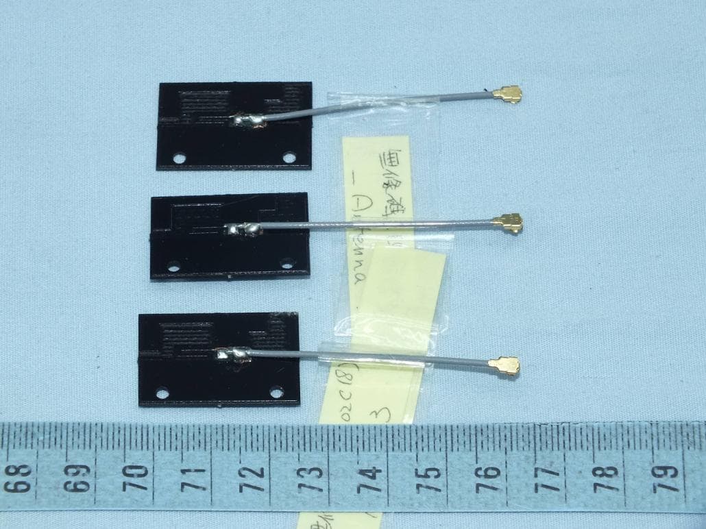
YHI-NW111
Jan 03, 20163x3 11n/g/b/a 2.4/5GHz WiFi Module
Equipment Class
DTS - Digital Transmission System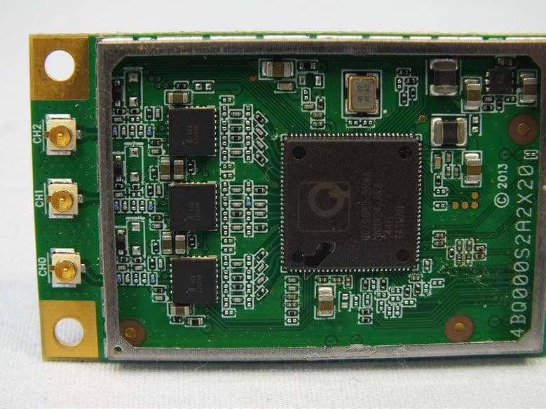
YHI-NW121
Dec 30, 20153x3 11ac/n/g/b/a 2.4/5GHz WiFi Module
Equipment Class
DTS - Digital Transmission System
YHI-EWF3210K
Apr 29, 2015Industrial IEEE 802.11a/b/g/n AP module
Equipment Class
DTS - Digital Transmission System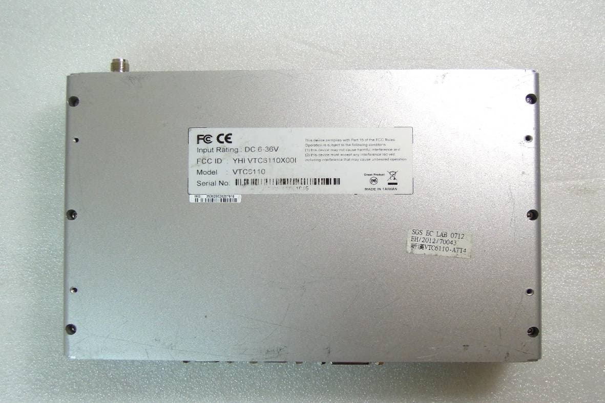
YHI-VTC6110ATT4
Sep 09, 2012VTC6110-ATT4
Equipment Class
PCB - PCS Licensed Transmitter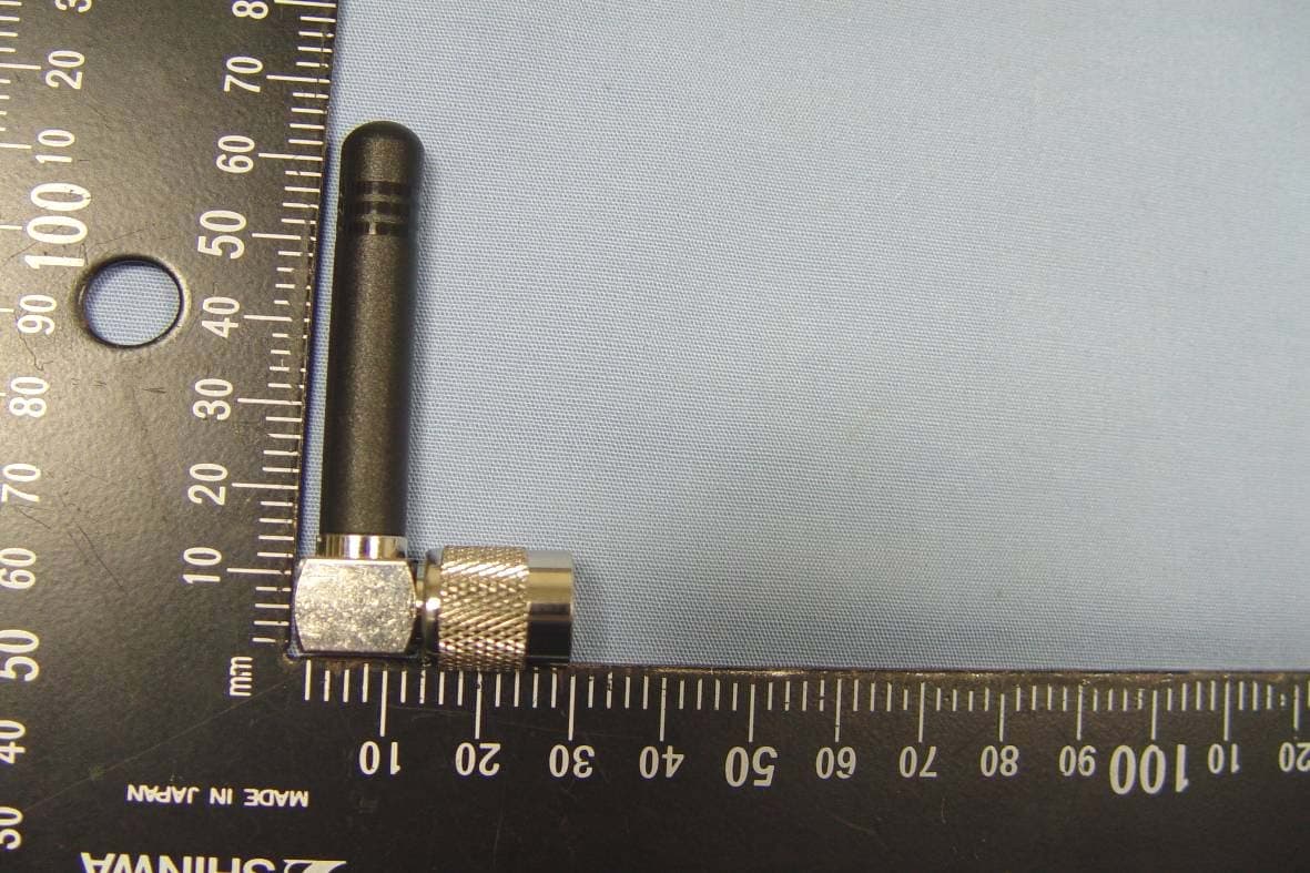
YHI-VTC6110X00
Sep 29, 2010Intelligent Vehicle Telematics Computer
Equipment Class
PCB - PCS Licensed Transmitter