YI5-R05F2RECTessonics Receiver
Celadon, Inc.
Click to zoom
Application Details
- Equipment Class
- DTS - Digital Transmission System
- Date of Grant
- Aug 29, 2022
- Application Purpose
- Original Equipment
- Date of Application
- Aug 29, 2022
- Equipment Note
- Tessonics Receiver
- Frequency Range
- 2402.00000000 - 2480.00000000
- Company
- Celadon, Inc.
- Country
- United States
Documents & Files
Document Text
Text extracted from the exhibit documents filed with the FCC. Open a document above to read the original.
Users Manual
Manual Introduction The Tessonics Receiver is designed to be integrated into the RSWA System to receive from the Tessonics Remote Control. The RSWA System is a portable Ultrasonic Quality Inspection Platform used for the automotive industry. The operator will use the remote control to operate the system to produce ultrasonic c-scan images of defects and structures within spot welds and adhesive joints. Receiver module Model : R05-F-2-RECEIVER Description : Tessonics Receiver Applicant : Celadon Inc. Manufacturer Factory : Hyun Seung I&C Co., Ltd RF IC : Nordic semiconductor NRF52833 Communication with RSWA system through 12505WR-05 connector Input rated : 5.0 Vd.c, 0.5 A Size : 18.0 x 28.0 (mm), 1.6T RSWA system R05-F-2-Receiver PCBA is used only with RSWA system Rx RSWA System HIDK/D2.4GHz FCC Compliance Statement This device complies with part 15 of the FCC rules. Operation is subject to the following two conditions: (1) This device may not cause harmful interference, and (2) this device must accept any interference received, including interference that may cause undesired operation. FCC Caution : Any changes or modifications to the equipment not expressly approved by the party responsible for compliance could void your authority to operate the equipment. This transmitter must not be co-located or operating in conjunction with any other antenna or transmitter. FCC ID : YI5-R05F2REC Information on test modes and additional testing requirements a)The modular transmitter has been fully tested by the module grantee on the required number of channels, modulation types and modes, it should not be necessary for the host installer to re-test all the available transmitter modes or settings. It is recommended that the host product manufacturer installing the modular transmitter, perform some investigative measurements to confirm that the resulting composite system does not exceed the spurious emissions limits or band edge limits (e.g.,wherea different antenna may be causing additional emissions). b)The testing should check for emissions that may occur due to the intermixing of emissions with the other transmitter, digital circuitry, or due to physical properties of the host product(enclosure). This investigation is especially important when integrating multiple modular transmitters where the certification is based on testing each of them in a stand-alone configuration. It is important to note that host product manufactures should not assume that because the modular transmitter is certified that they do not have any responsibility for final product compliance. c)If the investigation indicates a compliance concern the host product manufacture is obligated to mitigate the issue. Host products using a modular transmitter are subject to all the applicable individual technical rules as well as to the general conditions of operation in Sections 15.5,15.15,and 15.29 to not cause interference. The operator of the host product will be obligated to stop operating the device until the interference has been corrected. Additional testing, Part 15 subpart B disclaimer The final host/module combination need to be evaluated against the FCC Part 15B criteria for unintentional radiators in order to be properly authorized for operation as a Part 15 digital device. The host integrator installing this module into their product must ensure that the final composite product complies with the FCC requirements by a technical assessment or evaluation to the FCC rules, including the transmitter operation and should refer to guidance in KDB 996369. This appliance and its antenna must not be co-located or operation in conjunction with any other antenna or transmitter. -OEM integrators must ensure that its product is electrically identical to the device, FCC ID: FCC ID : YI5-R05F2REC reference designs. Any modifications to module reference designs may invalidate regulatory approvals in relation to the product, or may necessitate notifications to the relevant regulatory authorities. -OEM integrators are responsible for regression testing to accommodate changes to designs, new antennas, and host and submit for C2PC filings. -Colocation with other transmitter modules will be addressed through filings for those co-located transmitters when necessary or that colocation of other transmitters will be according to applicable KDB guidelines including those for RF exposure. -Appropriate labels must be affixed to the product that complies with applicable regulations in all respects. The regulatory label on the final system must include the statement: “Contains FCC ID: YI5-R05F2REC” Industry Canada Statement This device complies with Industry Canada license-exempt RSS standard(s). Operation is subject to the following two conditions: (1) this device may not cause interference, and (2) this device must accept any interference, including interference that may cause undesired operation of the device. Ce dispositifestconformeà la normeCNR-247 d’IndustrieCanada applicable aux appareilsradio exempts de licence. Son fonctionnementestsujetaux deux conditions suivantes: (1) le dispositifne doitpas produirede brouillage préjudiciable, et (2) cedispositifdoitaccepter tout brouillagereçu, y comprisun brouillagesusceptible de provoquerun fonctionnementindésirable. IC = 9065A-R05F2REC
Cover Letter(s)
Page 1 / 3 Applicant / Grantee Celadon, Inc. FCC ID YI5-R05F2REC Section 15.212 Modular Transmitters Request for Modular Approval Request for Limited Modular Approval Requirements EUT Conditions Comply (Y/N) Single Modular Approval Requirements 1 The radio elements of the modular transmitter must have their own shielding. The physical crystal and tuning capacitors may be located external to the shielded radio elements. This device may not meet the requirements for RF shielding , and thus a limited Modular Approval is requested at this time. N 2 The modular transmitter must have buffered modulation/data inputs (if such inputs are provided) to ensure that the module will comply with Part 15 requirements under conditions of excessive data rates or over- modulation. All input to the modules are buffered through IC in module include logic and Microprocessor. Y 3 The modular transmitter must have its own power supply regulation. Power supply regulation built into IC on module. Refer to the circuit diagram. Y 4 The modular transmitter must comply with the antenna and transmission system requirements of Sections 15.203, 15.204(b) and 15.204(c). The antenna must either be permanently attached or employ a “unique” antenna coupler (at all connections between the module and the antenna, including the cable). The “professional installation” provision of Section 15.203 is not applicable to modules but can apply to limited modular approvals under paragraph (b) of this section. This module has one Chip antenna. The antenna will be installed permanently within the module. Y 5 The modular transmitter must be tested in a stand-alone configuration, i.e., the module must not be inside another device during testing for compliance with Part 15 requirements. Unless the transmitter module will be battery powered, it must comply with the AC line conducted requirements found in Section 15.207. AC or DC power lines and data input/output lines connected to the module must not contain ferrites, unless they will be marketed with the module (see Section 15.27(a)). The length of these lines shall be the length typical of actual use or, if that length is unknown, at least 10 centimeters Refer to the test setup photo Y Page 2 / 3 to insure that there is no coupling between the case of the module and supporting equipment. Any accessories, peripherals, or support equipment connected to the module during testing shall be unmodified and commercially available (see Section 15.31(i)). 6 The modular transmitter must be equipped with either a permanently affixed label or must be capable of electronically displaying its FCC identification number. (A) If using a permanently affixed label, the modular transmitter must be labeled with its own FCC identification number, and, if the FCC identification number is not visible when the module is installed inside another device, then the outside of the device into which the module is installed must also display a label referring to the enclosed module. This exterior label can use wording such as the following: “Contains Transmitter Module FCC ID: XYZMODEL1” or “Contains FCC ID: XYZMODEL1.” Any similar wording that expresses the same meaning may be used. The Grantee may either provide such a label, an example of which must be included in the application for equipment authorization, or, must provide adequate instructions along with the module which explain this requirement. In the latter case, a copy of these instructions must be included in the application for equipment authorization. (B) If the modular transmitter uses an electronic display of the FCC identification number, the information must be readily accessible and visible on the modular transmitter or on the device in which it is installed. If the module is installed inside another device, then the outside of the device into which the module is installed must display a label referring to the enclosed module. This exterior label can use wording such as the following: “Contains FCC certified transmitter module(s).” Any similar wording that expresses the same meaning may be used. The user manual must include instructions on how to access the electronic display. A copy of these instructions must be included The FCC label is permanently marked on the back of the PCBA. The instruction on the labeling rule of the end product has been stated in the user manual of this module. Please also see the exhibition Label Sample. Y Page 3 / 3 in the application for equipment authorization. 7 The modular transmitter must comply with any specific rules or operating requirements that ordinarily apply to a complete transmitter and the manufacturer must provide adequate instructions along with the module to explain any such requirements. A copy of these instructions must be included in the application for equipment authorization. Refer to the user manual Y 8 The modular transmitter must comply with any applicable RF exposure requirements in its final configuration. Refer to the RF exposure statement for more details. Y Robert Retzlaff / Chief Executive Officer Celadon, lnc.
External Photos
Model No.: R05-F-2-RECEIVER Page 1 of 2 External photos Model No.: R05-F-2-RECEIVER Page 2 of 2 N/A CHIP Antenna
ID Label/Location Info
Model No.: R05-F-2-RECEIVER Page 1 of 1 Label photo
Internal Photos
Model No.: R05-F-2-RECEIVER Page 1 of 1 Internal photos N/A CHIP Antenna
RF Exposure Info
Model Name : R05-F-2-RECEIVER Page 1 of 1 RF exposure FCC ID : YI5-R05F2REC According to FCC part 1.1310 : The criteria listed in the following table shall be used to evaluate the environment impact of human exposure to radio frequency (RF) radiation as specified in § 1.1307(b) Limits for Maximum Permissible Exposure (MPE) f= frequency in ㎒ Friis transmission formula: Pd = (Pout×G)/(4×pi×R 2 ) Where, Pd = power density in ㎽/㎠ Pout = output power to antenna in ㎽ G = gain of antenna in linear scale Pi = 3.1416 R = distance between observation point and center of the radiator in cm Pd the limit of MPE, 1 ㎽/㎠. If we know the maximum gain of the antenna and the total power input to the antenna, through the calculation, we will know the distance where the MPE limit is reached. Results Operation mode Frequency (㎒) Maximum Average output power (㏈m) Antenna gain (㏈i) Power density at 20 ㎝(㎽/㎠) Limit (㎽/㎠) TX 2 402 -8.50 7.29 0.001 5 1 2 442 -8.50 7.29 0.001 5 1 2 480 -8.50 7.29 0.001 5 1 Frequency range (㎒) Electric field strength(V/m) Magnetic field strength (A/m) Power density (㎽/㎠) Average time (A) Limits for Occupational / Control Exposures 300 – 1 500 -- -- f/300 6 1 500 - 100000 -- -- 5 6 (B) Limits for General Population / Uncontrol Exposures 300 – 1 500 -- -- f/1500 6 1 500 – 100 000 -- -- 1 30
Test Report
LLC ABRACON IS ISO9001-2015 CERTIFIED 5101 Hidden Creek Ln Spicewood TX 78669 Phone: 512-371-6159 | Fax: 512-351-8858 For terms and conditions of sale, please visit: www.abracon.com REVISED: 06.21.2018 High Gain 7.29dBi Ceramic Chip Antenna (2450MHz) ACAG0801-2450-T MSL = 1 RoHS/RoHS II Compliant Pb 8.0 x 1.0 x 1.0mm ELECTRICAL CHARACTERISTICS FEATURESAPPLICATIONS ItemSpec Centre Frequency (No matching)2857 MHz Centre Frequency (After matching)2450 MHz Bandwidth180 MHz typ VSWR Impedance Gain AzimuthOmni-directional PolarizationLinear Operating Temperature range-40°C ~+ 85°C MECHANICAL DIMENSIONS Antenna Dimensions Layout Dimensions • • Bluetooth • ZigBee • ISM applications • IoT and wearable • Remote Technology • M2M • • technology • • • Omni-directional Dimensions (mm) LLC ABRACON IS ISO9001-2015 CERTIFIED 5101 Hidden Creek Ln Spicewood TX 78669 Phone: 512-371-6159 | Fax: 512-351-8858 For terms and conditions of sale, please visit: www.abracon.com REVISED: 06.21.2018 High Gain 7.29dBi Ceramic Chip Antenna (2450MHz) ACAG0801-2450-T MSL = 1 RoHS/RoHS II Compliant Pb 8.0 x 1.0 x 1.0mm ANTENNA RESPONSE – SMITH CHART AND RETURN LOSS S11 EVALUATION BOARD AND MATCHING CIRCUITS LLC ABRACON IS ISO9001-2015 CERTIFIED 5101 Hidden Creek Ln Spicewood TX 78669 Phone: 512-371-6159 | Fax: 512-351-8858 For terms and conditions of sale, please visit: www.abracon.com REVISED: 06.21.2018 High Gain 7.29dBi Ceramic Chip Antenna (2450MHz) ACAG0801-2450-T MSL = 1 RoHS/RoHS II Compliant Pb 8.0 x 1.0 x 1.0mm RADIATION PATTERNS Coordinates X-Z Plane Y-Z Plane X-Y Plane LLC ABRACON IS ISO9001-2015 CERTIFIED 5101 Hidden Creek Ln Spicewood TX 78669 Phone: 512-371-6159 | Fax: 512-351-8858 For terms and conditions of sale, please visit: www.abracon.com REVISED: 06.21.2018 High Gain 7.29dBi Ceramic Chip Antenna (2450MHz) ACAG0801-2450-T MSL = 1 RoHS/RoHS II Compliant Pb 8.0 x 1.0 x 1.0mm REFLOW SOLDERING STANDARD CONDITION Frequency (MHz)240024502500 Peak Gain (dBi) 3D PATTERNS LLC ABRACON IS ISO9001-2015 CERTIFIED 5101 Hidden Creek Ln Spicewood TX 78669 Phone: 512-371-6159 | Fax: 512-351-8858 For terms and conditions of sale, please visit: www.abracon.com REVISED: 06.21.2018 High Gain 7.29dBi Ceramic Chip Antenna (2450MHz) ACAG0801-2450-T MSL = 1 RoHS/RoHS II Compliant Pb 8.0 x 1.0 x 1.0mm PACKAGING Dimensions: mm CAUTIONS 1. Static voltage 2. Ultrasonic cleaning 3. Soldering Package TypeQuantity/Size 1500 pcs/reel Centre Frequency (After matching)15000 pcs/carton Carton MSL - 1
Test Report
KES Co., Ltd. 3701, 40, Simin-daero 365beon-gil, Dongan-gu, Anyang-si, Gyeonggi-do, 14057, Korea Tel: +82-31-425-6200 / Fax: +82-31-424-0450 www.kes.co.kr Test report No.: KES-RF1-22T0109 Page (2) of (38) This report shall not be reproduced except in full, without the written approval of KES Co., Ltd. The results shown in this test report refer only to the sample(s) tested unless otherwise stated. The authenticity of the test report, contact [email protected] KES-QP-7081-06 Rev. 7 KES A4 Revision history Revision Date of issue Test report No. Description - 2022.08.17 KES-RF1-22T0109 Initial KES Co., Ltd. 3701, 40, Simin-daero 365beon-gil, Dongan-gu, Anyang-si, Gyeonggi-do, 14057, Korea Tel: +82-31-425-6200 / Fax: +82-31-424-0450 www.kes.co.kr Test report No.: KES-RF1-22T0109 Page (3) of (38) This report shall not be reproduced except in full, without the written approval of KES Co., Ltd. The results shown in this test report refer only to the sample(s) tested unless otherwise stated. The authenticity of the test report, contact [email protected] KES-QP-7081-06 Rev. 7 KES A4 TABLE OF CONTENTS 1. General information ...................................................................................................... 4 1.1. EUT description ............................................................................................... 4 1.2. Test configuration ............................................................................................. 5 1.3. Derivative Model Information ............................................................................... 5 1.4. Accessory information ........................................................................................ 5 1.5. Sample calculation ............................................................................................ 5 1.6. Measurement Uncertainty .................................................................................... 5 1.8. Frequency/channel operations ................................................................................ 6 2. Summary of tests ......................................................................................................... 6 3. Test results ............................................................................................................. 7 3.1. 99% Occupied Bandwidth .................................................................................... 7 3.2. 6 ㏈ bandwidth .............................................................................................. 9 3.3. Output power ................................................................................................ 11 3.4. Power spectral density ...................................................................................... 13 3.5. Radiated restricted band and emissions .................................................................... 15 3.6. Conducted spurious emissions & band edge .............................................................. 31 3.7. AC conducted emissions ................................................................................... 35 Appendix A. Measurement equipment.................................................................................... 37 Appendix B. Test setup photos ............................................................................................ 38 KES Co., Ltd. 3701, 40, Simin-daero 365beon-gil, Dongan-gu, Anyang-si, Gyeonggi-do, 14057, Korea Tel: +82-31-425-6200 / Fax: +82-31-424-0450 www.kes.co.kr Test report No.: KES-RF1-22T0109 Page (4) of (38) This report shall not be reproduced except in full, without the written approval of KES Co., Ltd. The results shown in this test report refer only to the sample(s) tested unless otherwise stated. The authenticity of the test report, contact [email protected] KES-QP-7081-06 Rev. 7 KES A4 1. General information Applicant: Celadon, Inc. Applicant address: 58 Paul Drive, Suite D, San Rafael, CA 94903 U.S.A Test site: KES Co., Ltd. Test site address: 3701, 40, Simin-daero 365beon-gil, Dongan-gu, Anyang-si, Gyeonggi-do, 14057, Korea 473-29, Gayeo-ro, Yeoju-si, Gyeonggi-do, Korea Test Facility FCC Accreditation Designation No.: KR0100, Registration No.: 444148 ISED Registration No.: 4769B FCC rule part(s): 15.247 IC rule part(s): RSS-247 FCC ID: YI5-R05F2REC IC Certification 9065A-R05F2REC Test device serial No.: Production Pre-production Engineering 1.1. EUT description Equipment under test Tessonics Receiver Frequency range 2 402 ㎒ ~ 2 480 ㎒ (BLE 2 Mbps) Model R05-F-2-RECEIVER Modulation technique GFSK Antenna specification Chip Antenna // Peak gain: 7.29 ㏈i Power source DC 3.3 V Number of channels 2 402 ㎒ ~ 2 480 ㎒ (BLE 2 Mbps) : 40 ch H/W Version Ver.01A S/W Version Ver.01A KES Co., Ltd. 3701, 40, Simin-daero 365beon-gil, Dongan-gu, Anyang-si, Gyeonggi-do, 14057, Korea Tel: +82-31-425-6200 / Fax: +82-31-424-0450 www.kes.co.kr Test report No.: KES-RF1-22T0109 Page (5) of (38) This report shall not be reproduced except in full, without the written approval of KES Co., Ltd. The results shown in this test report refer only to the sample(s) tested unless otherwise stated. The authenticity of the test report, contact [email protected] KES-QP-7081-06 Rev. 7 KES A4 1.2. Test configuration The Celadon, Inc // Tessonics Receiver // R05-F-2-RECEIVER FCC ID: YI5-R05F2REC // IC: 9065A-R05F2REC was tested according to the specification of EUT, the EUT must comply with following standards and KDB documents. FCC Part 15.247 ISED RSS-247 Issue 2 and RSS-Gen Issue 5 KDB 558074 D01 v05 r02 ANSI C63.10-2013 1.3. Derivative Model Information N/A 1.4. Accessory information Equipment Manufacturer Model Serial No. Power source - - - - - 1.5. Sample calculation Where relevant, the following sample calculation is provided For all conducted test items : The offset level is set in the spectrum analyzer to compensate the RF cable loss and attenuator factor between EUT conducted output port and spectrum analyzer. …
Text truncated - open the document above for the full version.
Test Setup Photos
KES Co., Ltd. 3701, 40, Simin-daero 365beon-gil, Dongan-gu, Anyang-si, Gyeonggi-do, 14057, Korea Tel: +82-31-425-6200 / Fax: +82-31-424-0450 www.kes.co.kr Test report No.: KES-RF1-22T0109 Page (37) of (37) This report shall not be reproduced except in full, without the written approval of KES Co., Ltd. The results shown in this test report refer only to the sample(s) tested unless otherwise stated. The authenticity of the test report, contact [email protected] KES-QP-7081-06 Rev. 7 KES A4 Appendix B. Test setup photos Radiated emissions N/A The end of test report.
Contact Information
Applicant
Robert Retzlaff(CEO)
Test Firm
KES Co., LtdInsung Ryu
Technical Specifications
| # | Rule Parts | Frequency Range | Power Output |
|---|---|---|---|
| 1 | 15C | 2.40 GHz - 2.48 GHz | 183.00 µW |
Other Applications from Celadon, Inc.
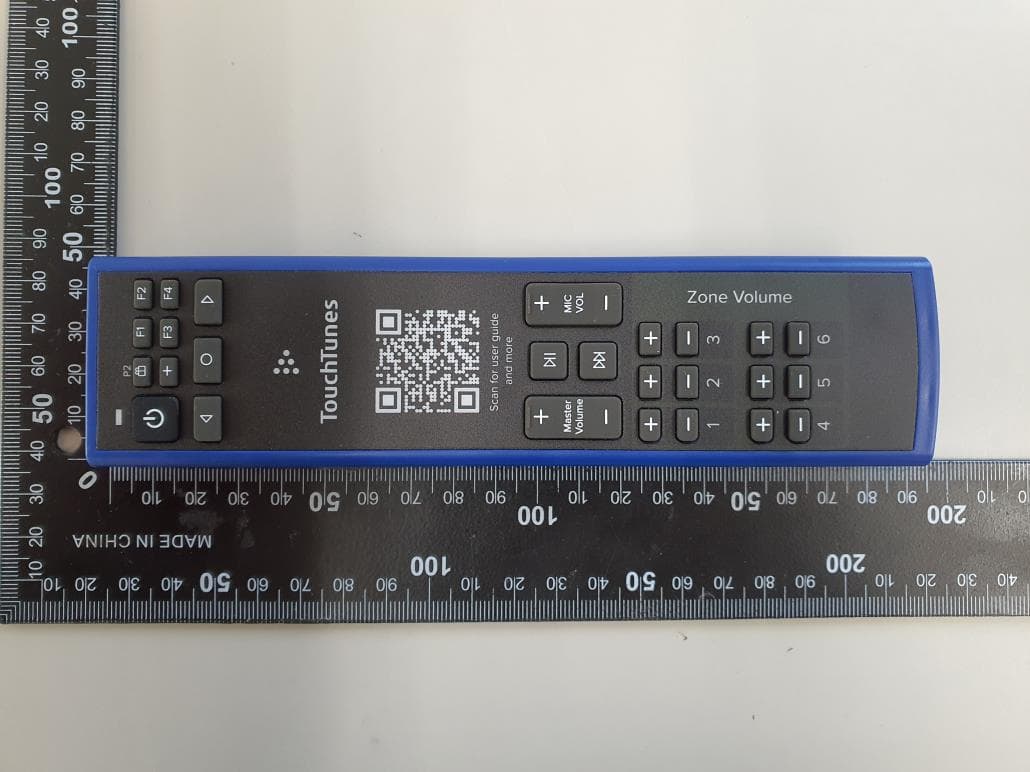
YI5HRC540ATT02
Apr 03, 2024433MHz Remote control
Equipment Class
DSC - Part 15 Security/Remote Control Transmitter
YI5-REM01
Feb 20, 2024Flex VRA Remote Control
Equipment Class
DSC - Part 15 Security/Remote Control Transmitter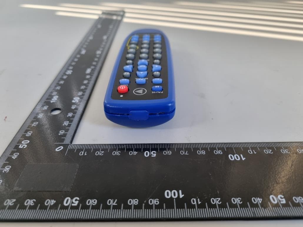
YI5SC33TT04
Feb 03, 2022Remote Control Unit
Equipment Class
DSC - Part 15 Security/Remote Control Transmitter
YI5-RCV3000RF01
Jul 20, 2010Tessonics RF Receiver
Equipment Class
DXT - Part 15 Low Power Transceiver, Rx Verified
YI5-FGSK18RF01
Jul 20, 2010Tessonics RF Remote
Equipment Class
DXT - Part 15 Low Power Transceiver, Rx Verified