YI5SC33TT04Remote Control Unit
Celadon, Inc.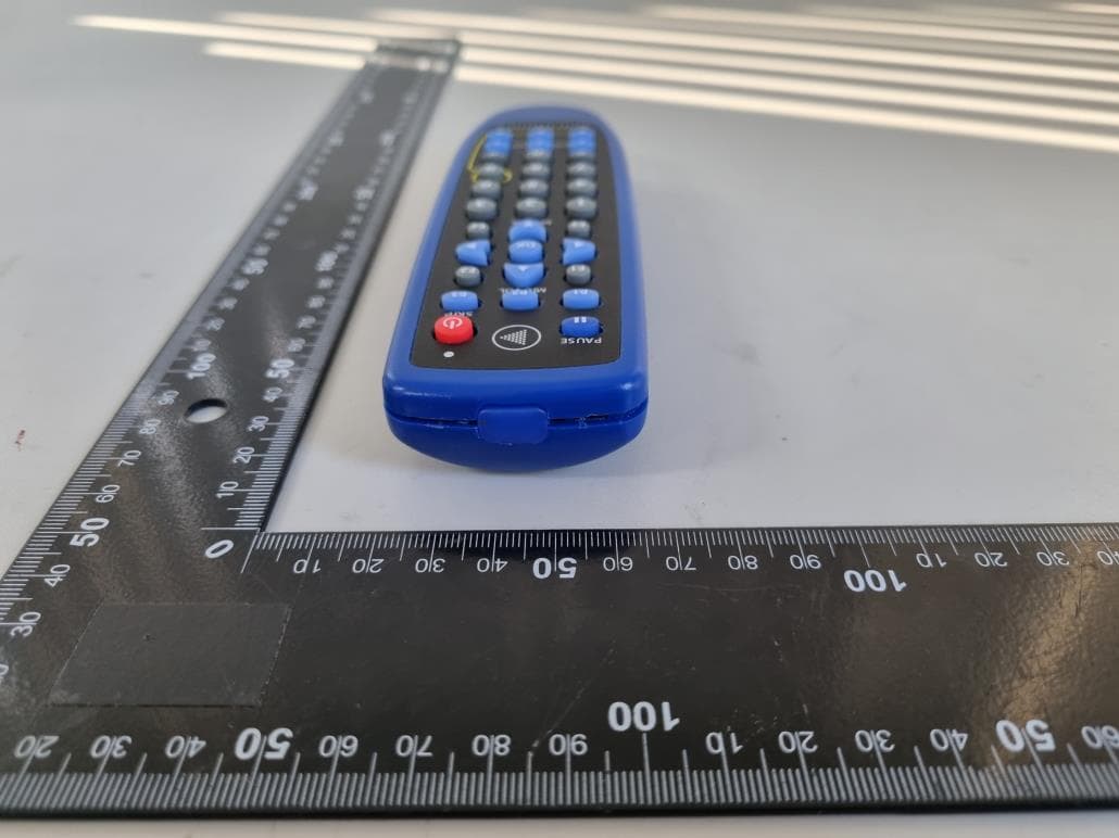
Click to zoom
Application Details
- Equipment Class
- DSC - Part 15 Security/Remote Control Transmitter
- Date of Grant
- Feb 03, 2022
- Application Purpose
- Original Equipment
- Date of Application
- Feb 03, 2022
- Equipment Note
- Remote Control Unit
- Frequency Range
- 433.92000000 - 433.92000000
- Company
- Celadon, Inc.
- Country
- United States
Documents & Files
Document Text
Text extracted from the exhibit documents filed with the FCC. Open a document above to read the original.
Users Manual
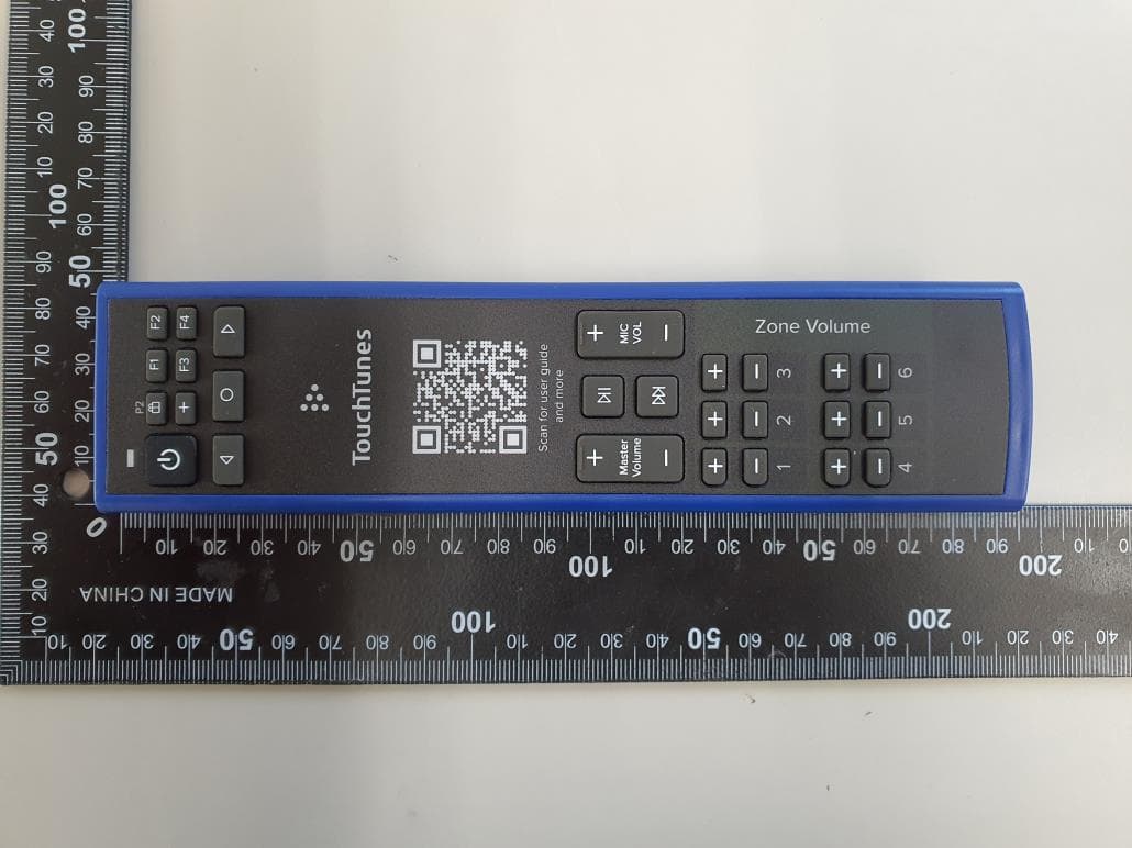
Copyright ⓒ 2022. Lab-T, Inc. User Manual 1 of 6 About This Guide This guide explains the setup and operation of TouchTunes wireless remote control, P/N 700194-00x (which should be ordered as P/N 600069-00x. Package Contents • Remote control (part number 700194-00x, which should be ordered as P/N 600069-00x) • Mounting bracket (part number 400188-001) • 2 AAA alkaline batteries • This guide Overview TouchTunes’ wireless remote control is a single-frequency remote that transmits a 433.92 MHz (FSK) signal to TouchTunes jukeboxes manufactured after 2005. Figure 1-1 Single-Frequency Wireless Remote Single-Frequency Remote Control User Guide January 2022 900303-001 Rev. 05 Use the mounting bracket to install the remote control on a wall for easy access. Fasten the bracket to the wall with two screws as illustrated. The red indicator LED flashes when the remote transmits or when it is being programmed. 2 of 6 The remote control has integrated flash memory to help prevent it from losing its ID when batteries drain. It also has a membrane and plastic framing for resistance to liquids, although it is not waterproof. The remote control is RF-based, which eliminates the need to point it directly at the jukebox. It has a range of up to 200 feet depending on the type of obstructions between it and the jukebox. (e.g., concrete and metal can provide more of a barrier than wood or plaster.) The remote control can also be affected by interference from other RF-based devices. The remote control is powered by two 1.5V AAA batteries. Insert the batteries in the compartment on the rear of the remote. Use only high-quality alkaline batteries. Setting the Remote Control ID By default, the remote control ID is set to 000. To change it, do the following: 1.Press the POWER and F4 keys at the same time and hold them down until the red indicator light blinks two times. Figure 1-2 Setting Remote ID 2.Enter a new three-digit code to be programmed. The new code must be in the range 000 to 255. 3.The red indicator light will light up for three seconds to confirm your selection. If you enter an invalid code the light will blink five times. 4.You must now have the jukebox re-learn the remote ID. Press and hold to set remote control ID. 3 of 6 Learning the Remote ID 1.On the Operator Menu, open the Hardware Options screen. 2.Press the LEARN button. 3.Watch the display. When prompted, press the MIC VOL UP key on the remote control. The display will show a success message and return to the Options screen. 4.Test the remote by raising and lowering the jukebox volume as it is playing. 4 of 6 Key Assignments and Functionality KeyFunction Power Press to turn the jukebox monitor and audio subsystem on or off. The jukebox computer remains on. Equivalent to pressing the Night Mode button on the jukebox (not available on all models). Pause Pauses the jukebox. Numeric keys Used to program the remote and for these optional features: • 2 and 8 to change the CMP channel, and 5 to confirm the change • 9 to toggle between the volume controls of zones 1-2-3 (default) and 4-5-6 (4-5-6 are not available on Gen3/+ jukeboxes.) MIC VOL Raises and lowers the volume of the microphone within the limits set on the Mixer Settings screen. P1 Press and release this button to add a promotional credit to the jukebox (if available). Credits are deducted from the promotional credit pool. The Promo Credit feature can be enabled/ disabled on the Credit Settings screen or through Tempo > Location > Settings > Money. P2 Press to display an activation code used by Bar Rewards to register as a staff member for this venue and jukebox. P3/Skip Skip song: Quickly press and release this button to stop playing the current song and immediately skip forward to the next song in the queue. The skip song feature can be enabled/disabled on the System Settings screen or through Tempo > Location > Settings > Jukebox > Remote. Flush play queue: Press and hold this button for four seconds to flush the entire play queue. VOLUME ZONE 1-2-3 / 4-5-6 Raises and lowers the volume of the selected zone within the limits set on the Sound Mixer screen. Pressing 9 on the keypad will toggle volumes between Zones 1/2/3 and Zones 4/5/6 on OS2 jukeboxes F1, F2, F3, F4 For future use. Left-arrow, right-arrow, OK For future use. 5 of 6 Zone Management On OpenStage 2 jukeboxes, the jukebox’s Zone Management settings allow you to split the three existing output zones, for a total of up to 6 mono output zones whose volumes can be managed independently. This allows venues to double their jukebox music coverage areas, offer- ing further customization in venue and an increased revenue opportu- nity. Zone Management is not available on Gen3/3+ jukeboxes; these jukeboxes only offer the standard 3 zones. The wireless remote has been updated with a decal that reflects these new volume control options. Switching between Zone Sets Press the ‘9’ button on the remote control to toggle between controlling Zones 1 to 3, or Zones 4 to 6. The LED Array (on Virtuo) or On-Screen Display (OSD) will display the text “ZONE 1-2-3 VOL” or “ZONE 4-5-6 VOL” for a moment. When a zone is not split, the volume buttons control that zone regard- less of the current zone set. For example, if zone 5 is not enabled, the zone 2/5 buttons will always change the volume of zone 2, even when you’ve pressed 9 to control the volumes of zones 4-5-6. Auto-Revert If toggled to Zone Set 4-5-6 using the 9 key, after a few minutes, the vol- ume zone set will automatically revert to 1-2-3. This is indicated on the LED Array or on-screen display by showing “ZONE 1-2-3 VOL”. Changing the Volume Pressing the volume up or down buttons on the remote for a particular zone will move the volume up or down accordingly for that zone, and at the same time, the LED Array (on a Virtuo) or the On-Screen Display (on other jukeboxes) will indicate which zone is being changed and how its volume is changing. The volume controls function differently if the S…
Text truncated - open the document above for the full version.
External Photos
Page: 1 / 4 Copyright ⓒ 2022, Lab-T, Inc. External Photos Page: 2 / 4 Copyright ⓒ 2022, Lab-T, Inc. External Photos Front Rear Page: 3 / 4 Copyright ⓒ 2022, Lab-T, Inc. External Photos Top Bottom Page: 4 / 4 Copyright ⓒ 2022, Lab-T, Inc. External Photos Left Right
ID Label/Location Info
Copyright ⓒ 2022. Lab-T, Inc. Label Informaion [FGSC33-TT-04 라벨도안 및 부착 위치] 변경 : 2022/01/21
Internal Photos
Page: 1 / 3 Copyright ⓒ 2022. Lab-T, Inc. Internal Photos Page: 2 / 3 Copyright ⓒ 2022. Lab-T, Inc. Internal Photos Main Board Front Main Board Rear Antenna Page: 3 / 3 Copyright ⓒ 2022. Lab-T, Inc. Internal Photos Main Board Front_Zoom in Inside
RF Exposure Info
1. Regulation 580056 mW71 mW85 mW97 mW106 mW 245083 mW123 mW173 mW235 mW309 mW 350086 mW124 mW170 mW225 mW290 mW 83580 mW92 mW105 mW117 mW130 mW 190099 mW153 mW225 mW316 mW431 mW ≤300 223 mW254 mW284 mW315 mW345 mW 450141 mW159 mW177 mW195 mW213 mW 58001 mW6 mW15 mW27 mW41 mW Frequency (MHz) Exemption Limits (mW) At separation distance of 30 mm At separation distance of 35 mm At separation distance of 40 mm At separation distance of 45 mm At separation distance of 50 mm 24504 mW7 mW15 mW30 mW52 mW 35002 mW6 mW16 mW32 mW55 mW 83517 mW30 mW42 mW55 mW67 mW 19007 mW10 mW18 mW34 mW60 mW ≤300 71 mW101 mW132 mW162 mW193 mW 45052 mW70 mW88 mW106 mW123 mW RF EXPOSURE The SAR exclusion table from RSS-102 issue 5 A1 is reproduced below: Table 1: SAR evaluation – Exemption limits for routine evaluation based on frequency and separation distance Frequency (MHz) Exemption Limits (mW) At separation distance of ≤5 mm At separation distance of 10 mm At separation distance of 15 mm At separation distance of 20 mm At separation distance of 25 mm Copyright ⓒ 2022. Lab-T, Inc. Page :1 / 3 RF EXPOSURE KDB447498 was used as the guidance. SAR test exclusion considerations Step.1 For 100 MHz to 6 GHz and test separation distances ≤ 50 mm, the 1-g and 10-g SAR test exclusion threshold are determined by the following : [(max. power of channel, including tune-up tolerance, mW) / (min. test separation distance, mm)] · [√f(GHz)] ≤ 3.0 for 1-g SAR, and ≤ 7.5 for 10-g extremity SAR where f(GHz) is the RF channel transmit frequency in GHz Power and distance are rounded to the nearest mW and mm before calculation The result is rounded to one decimal place for comparison Step.2 For 100 MHz to 6 GHz and test separation distances > 50 mm, the 1-g and 10-g SAR test exclusion thresholds are determined by the following {[Power allowed at numeric threshold for 50 mm in step a)] + [(test separation distance – 50 mm)· (f(MHz)/150)]} mW, for 100 MHz to 1500 MHz {[Power allowed at numeric threshold for 50 mm in step a)] + [(test separation distance – 50 mm)·10]} mW, for > 1500 MHz and ≤ 6 GHz Step.2-1 Step.2-2 The test exclusions are applicable only when the minimum test separation distance is ≤ 50 mm, and for transmission frequencies between 100 MHz and 6 GHz. When the minimum test separation distance is < 5 mm, a distance of 5 mm according to 4.1 f) is applied to determine SAR test exclusion. The values 3.0 and 7.5 are referred to as numeric thresholds in step b) below Copyright ⓒ 2022. Lab-T, Inc. Page :2 / 3 ( f(GHz) : the RF channel transmit frequency in GHz RF Exposure Compliance Issue Therefore, EUT is not required the SAR Evaluation. =0. 83P(mW) : Max tuneup Power (mW) R : Distance to the center of the radiation of the antenna5.00mm ) <3 Estimated SAR at the specific separation - S= [(P(mW) / R)] X [√f(GHz)] - NOTE =[(6.32/5.00)]X[√( 0.43392 )]S : Maximum Estimated SAR =0.25mW - PdBm- NOTE =6.32mW =8.01dBm+-14.11dBiP : Max tuneup Power (dBm) =-6.10dBmG : Maximum Peak Antenna Gain (dBi) - Maximum Peak Antenna Gain :-14.108dBi The EUT will only be used with a separation of 5 millimeters or lesser between the antenna and the body of the SAR Exclusion calculation for this exposure is shown below. - EIRP=P + G- NOTE =8.01dBm Antenna power 8.01 P : Max tuneup Power (dBm) - Measured RF Maximum Output Power :8.01 dBm = - Frequency Range :433.92 MHz~433.92 MHz EIRP Field strength=89.10dBμV/m @3m =-6.10dBm SAR test exclusion considerations FCCID : YI5SC33TT04 IC : 9065A-SC33TT04 Copyright ⓒ 2022. Lab-T, Inc. Page :3 / 3
Test Report
REPORT No.:TRRFCC22-0003 Total 20 pages TRF-R-003(00) Page: 2 / 20 Copyright ⓒ 2022 Lab-T, Inc. CONTENTS 1. Revision history ............................................................................................................................................... 3 2. Information ...................................................................................................................................................... 4 2.1 Applicant Information ................................................................................................................................................................. 4 2.2 Test Laboratory information ..................................................................................................................................................... 4 2.3 Test Site .............................................................................................................................................................................................. 4 3. Information About Test Equipment ............................................................................................................ 5 3.1 Equipment Information .............................................................................................................................................................. 5 3.2 Antenna Information ................................................................................................................................................................... 5 3.3 Test Frequency ................................................................................................................................................................................ 5 3.4 Operating conditions for the EUT ......................................................................................................................................... 5 4. Test Report ....................................................................................................................................................... 6 4.1 Summary ................................................................................................................................ ........................................................... 6 4.2 Measurement Uncertainty ......................................................................................................................................................... 6 4.4 Transmitter Requirements ......................................................................................................................................................... 7 4.4.1 Antenna Requirement ......................................................................................................................................................... 7 4.4.2 Transmitter Deactivation .................................................................................................................................................... 8 4.4.3 Field Strength of Emissions .............................................................................................................................................. 9 4.4.4 Emission Bandwidth ...........................................................................................................................................................11 4.4.5 Spurious Emission and Restricted bands .................................................................................................................13 4.4.6 Conducted Emission ..........................................................................................................................................................17 4.4.7 Duty cycle ...............................................................................................................................................................................18 APPENDIX I ............................................................................................................................................................ 19 REPORT No.:TRRFCC22-0003 Total 20 pages TRF-R-003(00) Page: 3 / 20 Copyright ⓒ 2022 Lab-T, Inc. 1. Revision history Test Report No. Date Description TRRFCC22-0003 2022-01-27 Initial issue REPORT No.:TRRFCC22-0003 Total 20 pages TRF-R-003(00) Page: 4 / 20 Copyright ⓒ 2022 Lab-T, Inc. 2. Information 2.1 Applicant Information Applicant name Celadon, Inc. Address 58 Paul Drive, Suite D, San Rafael, CA 94903 United States Telephone No. 415-472-1177 x201 Person in charge Robert Retzlaff / [email protected] Manufacturer Celadon, Inc. Address 58 Paul Drive, Suite D, San Rafael, CA 94903 United States 2.2 Test Laboratory information Corporate name Lab-T, Inc. Representative Duke (Jongyoung) Kim Address 2182-42 Baegok-daero, Mohyeon-eup, Cheoin-gu, Yongin-si, Gyeonggi-do 17036, Korea(Republic of) Telephone +82-31-322-6767 Fax +82-31-322-6768 E-mail [email protected] FCC Designation No. KR0159 FCC Registration No. 133186 IC Registration No. 22000 2.3 Test Site Test Site used Address Building L 2182-40 Baegok-daero, Mohyeon-eup, Cheoin-gu, Yongin-si, Gyeonggi-do 17036, Korea(Republic of) Building T 2182-42 Baegok-daero, Mohyeon-eup, Cheoin-gu, Yongin-si, Gyeonggi-do 17036, Korea(Republic of) Building A 2182-44 Baegok-daero, Mohyeon-eup, Cheoin-gu, Yongin-si, Gyeonggi-do 17036, Korea(Republic of) REPORT No.:TRRFCC22-0003 Total 20 pages TRF-R-003(00) Page: 5 / 20 Copyright ⓒ 2022 Lab-T, Inc. 3. Information About Test Equipment 3.1 Equipment Information Equipment type Remote Control Unit Model name FGSC33-TT-04 (P/N : 700194-004) Variant model name - Frequency 433.92 MHz Modulation type FSK Power supply DC 3.0 V H/W version 1.0A S/W version 1.0A NOTE1: The above EUT information was declared by the manufacturer. 3.2 Antenna Information Type Model No. Gain Note. PCB Pattern Antenna - -14.108 dBi - 3.3 Test Frequency Test mode Test frequency (MHz) Lowest frequency Middle frequency Highest f…
Text truncated - open the document above for the full version.
Test Setup Photos
Page: 1 / 3 Copyright ⓒ 2022. Lab-T, Inc. Test Setup Photos Page: 2 / 3 Copyright ⓒ 2022. Lab-T, Inc. Test Setup Photos Radiated Emission_9 kHz ~ 30 MHz Test distance : 3 m, height of table : 0.8 m Radiated Emission_30 MHz ~ 1 GHz Test distance : 3 m, height of table : 0.8 m Page: 3 / 3 Copyright ⓒ 2022. Lab-T, Inc. Test Setup Photos Radiated Emission_Above 1 GHz Test distance : 1 m, height of table : 1.5 m
Contact Information
Applicant
Robert Retzlaff(CEO)
Test Firm
Lab-T, Inc.Lee Cheol-ho
Technical Specifications
| # | Rule Parts | Frequency Range | Power Output |
|---|---|---|---|
| 1 | 15.231 | 433.92 MHz - 433.92 MHz | - |
Other Applications from Celadon, Inc.
YI5HRC540ATT02
Apr 03, 2024433MHz Remote control
Equipment Class
DSC - Part 15 Security/Remote Control Transmitter
YI5-REM01
Feb 20, 2024Flex VRA Remote Control
Equipment Class
DSC - Part 15 Security/Remote Control Transmitter
YI5-R05F2REC
Aug 29, 2022Tessonics Receiver
Equipment Class
DTS - Digital Transmission System
YI5-RCV3000RF01
Jul 20, 2010Tessonics RF Receiver
Equipment Class
DXT - Part 15 Low Power Transceiver, Rx Verified
YI5-FGSK18RF01
Jul 20, 2010Tessonics RF Remote
Equipment Class
DXT - Part 15 Low Power Transceiver, Rx Verified