YIKMIH55Mother Board
Shenzhen Jehe Technology Development Co.,Ltd.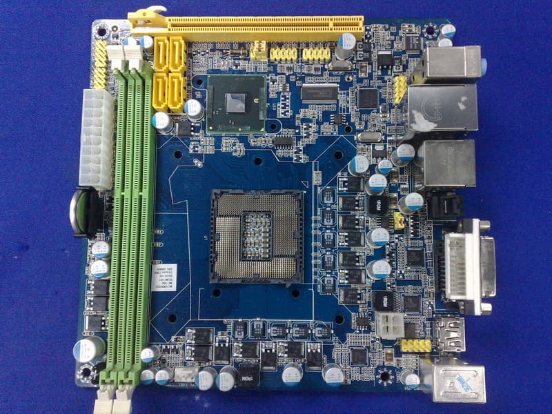
Click to zoom
Application Details
- Equipment Class
- JBC - Part 15 Class B Computing Device/Personal Computer
- Date of Grant
- Jul 25, 2010
- Application Purpose
- Original Equipment
- Date of Application
- Jul 25, 2010
- Equipment Note
- Mother Board
- Country
- China
Documents & Files
Document Text
Text extracted from the exhibit documents filed with the FCC. Open a document above to read the original.
Users Manual
All rights reserved www.giada.cc User's Manual Version 001 2 1 Gratitude ....................................................................................... I. About the product ........................................................................ 1. Accessories ........................................................................... 2. Picture of the motherboard ...................................................... 3. Features .............................................................................. 3.1 Processor ........................................................................ 3.2 Memory ........................................................................... 3.3 BIOS .............................................................................. 3.4 Interfaces of peripherals ...................................................... 3.5 Power management ............................................................ 3.6 Expansion slot .................................................................. II. Hardware installation ..................................................................... 1. Layout of motherboard ............................................................ 2. Installing memory .................................................................. 3. Install expansion slot card ......................................................... 3.1 Install graphic card ............................................................ 3.2 Install mini-PCIE extend devices .......................................... 4. Motherboard jumper setting ...................................................... 4.1 SATA1/SATA2/SATA3/SATA4 ................................................ 4.2 CPU_FAN1SYS_FAN1 ......................................................... 4.3 CLR_CMOS ..................................................................... 4.4 F_USB1/F_USB2 ............................................................... 4.5 F_AUDIO ........................................................................ 4.6 ATX20P ........................................................................... 4.7 F_PANEL ........................................................................ 5. Rear panel interface ............................................................... Contents III. BIOS setting .............................................................................. 1. Main manu ........................................................................... 2. Main (Standard BIOS Setup) ................................................... 3. Advanced (Advance BIOS Setup) ............................................. 3.1 CPU configuration ............................................................ 3.2 IDE configuration ............................................................... 3.3 IO Chipset configuration ...................................................... 3.4 PC Health configuration ...................................................... 4. Power .................................................................................... 5. Booting ................................................................................. 6. Security setup ........................................................................ 7. Setup for chipset ..................................................................... 8. Exit ....................................................................................... IV. Software installation ..................................................................... 1. Install driver for motherboard ................................................... 1.1 Install driver for chipset ...................................................... 1.2 Install sound card driver ...................................................... 1.3 Install driver for on-board LAN chip ....................................... 1.4 Install driver for graphic card ................................................ 2. HD_AUDIO and sound card setup ............................................. 3 4 4 5 5 5 5 6 6 7 8 9 10 11 10 11 12 12 13 14 15 16 17 18 4 5 19 21 232323 24 25 26 27 29 31 33 35 37 37 39 40 41 42 43 4 3 Gratitude I. About the product Dear Users,Thank you for choosing Giada “MI” series motherboard .Giada MI-H55 is based on INTEL LGA1156 processor, support Intel core i7, i5, i3 and Pentium. The motherboard also supports INTE L Hyper- Threading technology, 6.4GT/s and 4.8GT/s for QPI, and DDR3 1333/1066MHz memory standards. With on-board six-channel HD-AUD IO sound card and gigabit LAN. Support HDMI HD display output.As a highly compatible motherboard, MI-H55 stands out in terms of performance and price, satisfying needs of application in homes , offices or DIY. 1 Accessories Your MI-H55 Motherboard consists of the following accessories. If any of them is damaged or missing, please contact your local distributor as so on as possible. . 2. Picture of the motherboard NOTE: This is Giada MI-H55 real product photo show for your reference only, Product appearance depends on goods. Item No. 123456 Accessory's name MI-H55 Motherboard/ I/O baffle User's Manual Warranty Card/Certificate of Compliance Driver's cable SATA hard-disk cable Driver's disk Quantity 1 piece/1 piece 1 copy 1 copy/1 copy 1 piece 2 pieces 1 piece 6 5 · Eight high-speed transmission ports (max. 480Mb/s) which suppor t USB2.0 and are compatible with USB1.1; · Supports four SATA II hard-disk interfaces; · One RJ45 network interface; · On-board six-channel HD-AUDIO audio adapter; · Interfaces on panels can be compatible with HDD LED, Speaker, e tc. 3.5 Power management · Support APM and ACPI. · Compatible with energy star “Green PC”. 3.6 Expansion slot · One PCI Express x16 AGP · One MINI-PCIE 3. Features 3.1 Processor · Supports INTEL LGA1156 processor 3.2 Memory · Supports 240-Pin DDR3 1333/1066MHz memories * 2; · 8GB at maximum; · Supports dual-channel mode. 3.3 BIOS · Supports PNP, APM and ATAPI; · Supports ACPI a…
Text truncated - open the document above for the full version.
Users Manual
26 25 3.3 IO Chipset Configuration · Serial Port 1 Address (SI 1) To set the built-in serial port 1 (COM1 port). The options are: D i s a b l e d 、 3F8 / IRQ4, 2F8 / IRQ3, 3E8 / IRQ4, 2E8/ IRQ3 and Auto. The def ault value is “3F8 / IRQ4”. · Serial Port 1 Mode If set as Normal, it is for the use of regular mouse and Modem. If IR device (IrDA) is available, it is recommended it be set a s IrDA ASKIR. · Parallel Port Address To select the address of PI (parallel interface). Fig 3.5 · Parallel Port Mode To select the transmission mode (ECP/EPP/Normal) for PI. The de fault value is “Normal”. · Parallel Port IRQ Set IRQ for PI. It is recommended it be set as “7”. 3.4.PC Health Configuration · H/W Health Function Through this item, you can view the state of the system hardwar e. You can view the speed of the CPU fan, temperature of CPU and other val ues. · CPU Fan Speed Control To set the CPU fan's mode. Options include Manual Mode and Ther mal Cruise Mode. Fig 3.6 28 27 4. Power (power management) · To set the power type the system can support. · ACPI APIC support This item allows you decide whether acpi apic form to rsdt indi cation list. Options are [disabled] and [enabled]. · Power Management/APM This item is used for enabling or disabling the APM (advanced p ower management) function. The default value is “Enabled”. When [ena bled] is selected, BIOS can set the system as power-saving mode in accordance with the later setup even if no operating system pro vides any support. ACPI Version Features Fig 3.7 · Power Button Mode The defaulted value ON/OFF indicates that the system will turn ATX switch into a common shutoff button if the ATX switch is in the pressed- down state for less than four seconds. If Suspend is selected, it means the system will enter the sleeping mode if the ATX switch is in the pressed-down state for less than four seconds. Whatever option is selected, the system will be shut off if the ATX switch is in t he pressed- down state for over four seconds. · Restore on AC Power Loss This item is used for setting what state the system should be i n when the AC power is restored after power interruption. The options and their definitions are as follows: · Power On by PCI Card To start from PCI device. · Wake-Up by PCIE To wake up by PCIE. · RTC Resume If [Enabled] is selected, you can start the system through real -time clock. Option Power Off Power On Last State Definition To allow the system to be in shutoff state To allow the system to be started automatically To allow the system to keep the pre-power off state 30 29 5. Booting · If this item is set as Enabled, the system can be started withi n five seconds and some detection items will be ignored. The options a re [Disabled] and [Enabled]. · Quiet Boot To start the system quietly. · Add On ROM Display Mode [Force BIOS] This item allows you to set the display mode of the device's fi rmware program. The options are [Force BIOS] and [Keep Current]. · Bootup Num-Lock (To set the state of Num Lock after start-up). Options are OFF and ON. Quick Boot Fig 3.8 In other words, this item can be used for setting the state of Num Lock for the time the system has been started. It can be set on the basis of the needs of the user and doesn't affect the performance of the computer. · PS2 Mouse Support Set to support PS2 mouse. The available options are [Auto] and [Disable]. The default value is Auto. · Wait For“F1” If any Error (The system waits the user to press F1 if any error occurs from the computer). The options are Disable and Enable. Normally, it is set as Enable. Then if the computer has any error, a line of English w ords will appear on the screen, reminding the user of pressing F1 to ente r CMOS for setup. If it is set as Disable, that line of English words won't appear. However, if the words “ wait...” appear during the start up process and you press Del, the system can also enter CMOS for setup. · Hit “Del” Message Display (Information is displayed when the computer is started, sugges ting the user can press “Del” to enter the state for CMOS setup). The op tions are [Disable] and [Enable]. Normally, [Enable] is selected. Aft er [Enable] is selected, the information on how to enter the state for CMOS setup will be displayed at the time the computer is starte d. If [Disable] is selected, such information won't be displayed. How ever, if you press “Del” when the character “Wait......” appears at the t ime the computer is started, the system can also enter the state for CM OS setup. · Interrupt 19 Capture [Disabled] If you use some PCI extension cards with built-in firmware prog ram (like SCSI extension card) and you want to start the system thr ough Interrupt 19, you can set this item as [Enabled]. The options a re [Disabled] and [Enabled]. 32 31 · Boot Device Priority To set the booting priority. · Hard Disk Drives To set the booting priority of hard disk devices. · Removable Drives To set the booting priority of removable devices. · CD/DVD Drives To set the booting priority of CD/DVD-ROM devices. 6. Security Setup If this function is selected, the following information will ap pear: Enter New Password hhhhhh Fig 3.9 Then, enter the password with not more than eight characters an d press <Enter>. BIOS will requires to enter the password again. Once you enter it again, BIOS will save the set password. Once the password item is enabled, you will be required to ente r the password each time before the system goes to the set program of BIOS. The user can set this item through the Security Option in advan ced BIOS properties. If the item Security Option is set as System, the p assword will be required to be entered before the system guides and goes to the set program of BIOS. If set as Setup, the password will be required to be entered only before the system goes to the set program of BIOS . To delete the password, press <Enter> in the popped-up window t hat requires to enter the password. Then, information for confirmat ion will appea…
Text truncated - open the document above for the full version.
External Photos
FCC ID:YIKMIH55 page Audix Technology (Shenzhen) Co., Ltd. Report No. ACS-F10139 7-1 7. PHOTOGRAPH OF EUT Figure 1 Frontside of the Motherboard Figure 2 Backside of the Motherboard
Internal Photos
FCC ID:YIKMIH55 page Audix Technology (Shenzhen) Co., Ltd. Report No. ACS-F10139 7-1 7. PHOTOGRAPH OF EUT Figure 1 Frontside of the Motherboard Figure 2 Backside of the Motherboard
Test Report
FCC ID:YIKMIH55 Audix Technology (Shenzhen) Co., Ltd. Report No. ACS-F10139 APPLICATION FOR CERTIFICATION On Behalf of SHENZHEN JIEHE TECHNOLOGY DEVELOPMENT Co., Ltd Mother Board Model Number: Giada MI-H55 FCC ID: YIKMIH55 Prepared for : SHENZHEN JIEHE TECHNOLOGY DEVELOPMENT Co., Ltd 2/F, Block A, Tsinghua Information Harbor, North Section, Shenzhen Hi-tech Park, Nanshan District, Shenzhen, China P. R Prepared By : Audix Technology (Shenzhen) Co., Ltd. No. 6, Ke Feng Rd., 52 Block, Shenzhen Science & Industrial Park, Nantou, Shenzhen, Guangdong, China Tel: (0755) 26639496 Report Number : ACS-F10139 Date of Test : Jun.12~14, 2010 Date of Report : Jun.28, 2010 FCC ID:YIKMIH55 Audix Technology (Shenzhen) Co., Ltd. Report No. ACS-F10139 TABLE OF CONTENTS Description Page 1. SUMMARY OF STANDARDS AND RESULTS .................................................................. 1-1 1.1. Description of Standards and Results.............................................................................................1-1 2. GENERAL INFORMATION .................................................................................................. 2-1 2.1. Description of Device (EUT) .........................................................................................................2-1 2.2. Test configuration with EUT .........................................................................................................2-2 2.3. Tested Supporting System Details .................................................................................................2-2 2.4. Test Facility....................................................................................................................................2-6 2.5. Test Uncertainty (95% confidence levels, k=2) .............................................................................2-6 3. POWER LINE CONDUCTED EMISSION TEST................................................................ 3-1 3.1. Test Equipments.............................................................................................................................3-1 3.2. Block Diagram of Test Setup .........................................................................................................3-1 3.3. Power Line Conducted Emission Test Limits ................................................................................3-1 3.4. Configuration of EUT on Test .......................................................................................................3-2 3.5. Operating Condition of EUT..........................................................................................................3-2 3.6. Test Procedure................................................................................................................................3-2 3.7. Power Line Conducted Emission Test Results...............................................................................3-2 4. RADIATED EMISSION TEST ............................................................................................... 4-1 4.1. Test Equipment ..............................................................................................................................4-1 4.2. Block Diagram of Test Setup .........................................................................................................4-2 4.3. Radiated Emission Limit ................................................................................................................4-3 4.4. EUT Configuration on Test............................................................................................................4-3 4.5. Operating Condition of EUT..........................................................................................................4-3 4.6. Test Procedure................................................................................................................................4-3 4.7. Radiated Emission Test Results .....................................................................................................4-4 5. DEVIATION TO TEST SPECIFICATIONS ........................................................................ 5-1 6. PHOTOGRAPH OF TEST...................................................................................................... 6-1 6.1. Photos of Power Line Conducted Emission Test ...........................................................................6-1 6.2. Photos of Radiated Emission Test (In Anechoic Chamber) ...........................................................6-2 7. PHOTOGRAPH OF EUT........................................................................................................ 7-1 FCC ID:YIKMIH55 Page Audix Technology (Shenzhen) Co., Ltd. Report No. ACS-F10139 1-1 1. SUMMARY OF STANDARDS AND RESULTS 1.1. Description of Standards and Results The EUT have been tested according to the applicable standards as referenced below. EMISSION Description of Test Item Standard Limits Results Power Line Conducted Emission Test FCC Part 15: 2008 ANSI C63.4: 2009 Class B PASS Radiated Emission Test FCC Part 15: 2008 ANSI C63.4: 2009 Class B PASS FCC ID:YIKMIH55 Page Audix Technology (Shenzhen) Co., Ltd. Report No. ACS-F10139 2-1 2. GENERAL INFORMATION 2.1. Description of Device (EUT) Product name : Mother Board (Note) Model Number : Giada MI-H55 FCC ID : YIKMIH55 Highest clock frequency : 133MHz Applicant : SHENZHEN JIEHE TECHNOLOGY DEVELOPMENT Co., Ltd 2/F, Block A, Tsinghua Information Harbor, North Section, Shenzhen Hi-tech Park, Nanshan District, Shenzhen, China P.R Manufacturer : CHEER ASCENT Electronics Co., Ltd Block 1, Fuhai Industrial Park, Fuyong town, Baoan District, Shenzhen, China P.R Date of Test : Jun.12~14, 2010 Date of Receipt : Jun.07, 2010 Sample Type : Series production Note: This EUT is Class B personal computer main board, for test purpose, a typical Class B personal computer was configured by applicant with this EUT. FCC ID:YIKMIH55 Page A…
Text truncated - open the document above for the full version.
Test Setup Photos
FCC ID:YIKMIH55 Page 6-1 Audix Technology (Shenzhen) Co., Ltd. Report No. ACS-F10139 6. PHOTOGRAPH OF TEST 6.1. Photos of Power Line Conducted Emission Test FCC ID:YIKMIH55 Page 6-2 Audix Technology (Shenzhen) Co., Ltd. Report No. ACS-F10139 6.2. Photos of Radiated Emission Test (In Anechoic Chamber) 30~1000MHz FCC ID:YIKMIH55 Page 6-3 Audix Technology (Shenzhen) Co., Ltd. Report No. ACS-F10139 Above 1000MHz
Contact Information
Applicant
Barry Cheung(Product Manager)
Technical Contact
AUDIX Technology (Shenzhen) Co., Ltd.Lu Ken
[email protected]86-755-26639497
52 Block Shenzhen Science&Industry · Shenzhen · China
Test Firm
Audix Technology (Shenzhen) Co., Ltd.Smart Tsai
Technical Specifications
| # | Rule Parts | Frequency Range | Power Output |
|---|---|---|---|
| 1 | 15B | - | - |
Other Applications from Shenzhen Jehe Technology Development Co.,Ltd.
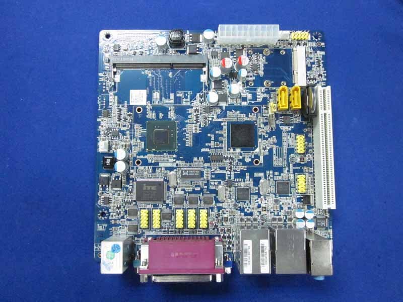
YIKMID525
Dec 15, 2010Mother Board
Equipment Class
JBC - Part 15 Class B Computing Device/Personal Computer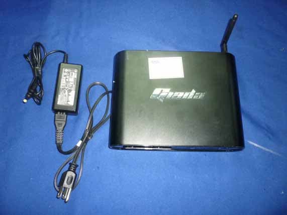
YIKD2301
Dec 08, 2010Mini PC
Equipment Class
JBC - Part 15 Class B Computing Device/Personal Computer
YIKMIION2
Nov 03, 2010Mother Board
Equipment Class
JBC - Part 15 Class B Computing Device/Personal Computer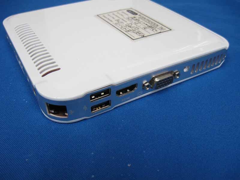
YIKI30
Aug 18, 2010Mini PC
Equipment Class
DTS - Digital Transmission System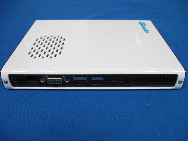
YIKI20PD
Aug 17, 2010Mini PC
Equipment Class
JBC - Part 15 Class B Computing Device/Personal Computer