YJ4CSAG200Stand Alone Gateway
Consert, Inc.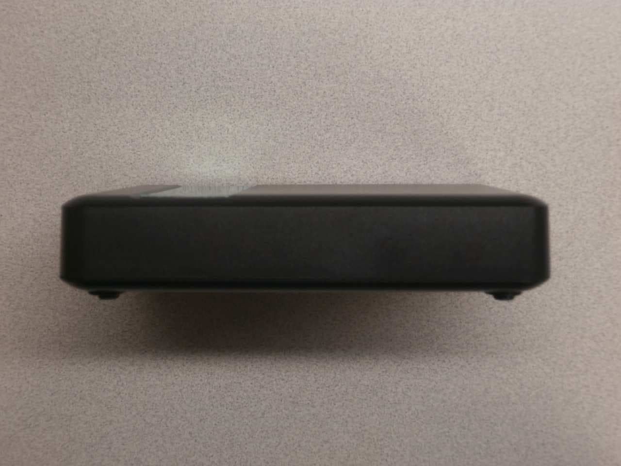
Click to zoom
Application Details
- Equipment Class
- DTS - Digital Transmission System
- Date of Grant
- Oct 16, 2014
- Application Purpose
- Original Equipment
- Date of Application
- Oct 16, 2014
- Equipment Note
- Stand Alone Gateway
- Frequency Range
- 2405.00000000 - 2480.00000000
- Company
- Consert, Inc.
- Country
- United States
Documents & Files
Document Text
Text extracted from the exhibit documents filed with the FCC. Open a document above to read the original.
Users Manual
5015 B.U. Bowman Drive Buford, GA 30518 USA Voice: 770-831-8048 Fax: 770-831-8598 Certification Exhibit FCC ID: YJ4CSAG200 FCC Rule Part: 15.247 ACS Project Number: 14-0047 Manufacturer: Consert, Inc. Model: CSAG200-1.0 Manual The Stand Alone Gateway enables electric utilities with existing communicating meters or AMI installations to deploy the Consert Load Management Suite of advanced solutions for residential and light commercial applications, including: The Stand Alone Gateway is self-contained with an unobtrusive design, and may be placed near any interior power source and either mounted to the wall or laid flat on a desktop. It supports multiple WAN interfaces including cellular, RF Mesh, WiFi and Ethernet. In addition, the Stand Alone Gateway utilizes two ZigBee ® subsystems. The fi rst is used to communicate to the existing ZigBee enabled meter, and the other is used as a communication conduit to the Consert Home Area Network, which includes Device Controllers and Programmable Communicating Thermostats. Consert’s Stand Alone Gateway does not require an existing communicating meter, although if one does exist they may work in tandem. Usage data and control options are available to consumers through a secure web portal accessible from any Web-enabled device. A separate portal for the electric utility provides a real-time graphic snapshot of aggregated loads at the home or device level via cellular or RF mesh communication. Options within Consert’s Load Management Solution Suite will present utilities with a real-time, device-level view and control for conservation events, analytics and ancillary services. • Virtual Peak Plant ™ • AC T-Stat Program• Intelligent AC Switch• Statistical VPP ™ CONSERT STAND ALONE GATEWAY overview Specifi cations • ARM9 400 MHz Processor (Atmel AT91SAM9G20) • 16 MB Flash/32 MB SDRAM • Embedded Linux OS • WAN -8 02 .11n WiFi radio (Marvel SD8787) -RJ45 Ethernet port -3G Gobi3000 radio (PCIE slot) • HAN -Two ZigBee radios (Ember EM357) -8 02 .11n WiFi radio (Marvel SD8787) -Expansion bus to support add-on radio modules (ZWave, GridStream, etc.) Electrical • External switching power supply supports 12 0 -24 0 VAC (50-60 Hz) Mechanical • Custom-tooled plastic enclosure • LED indicators -Active Conservation Mode -Consert Network Connectivity -Signal Strength -Power ZigBee • ZigBee (2.4 GHz) High Powered support (20 dBm transmit power) (UART/SPI interface) • Supports SEP 1.1 features and benefi ts Active Conservation ModeConsert Network ConnectivityPower OnSignal Strength www.consert.com regulatory information • Complies with Part 15 of the FCC Rules. • USA-Federal Communications Commission (FCC) Operation is subject to the following two conditions: 1. This device may not cause harmful interference, and 2. This device must accept any interference received, including interference that may cause undesired operation. Cautions Note • Any changes or modifications not expressly approved by the party responsible for compliance could void the user’s authority to operate the equipment. • Exposure to radio frequency radiation: To comply with FCC RF exposure compliance requirements, a separation distance of at least 20 cm must be maintained between the antenna of this device and all persons. This device must not be colocated or operating in conjunction with any other antenna or transmitter. This equipment has been tested and found to comply with the limits for a Class B digital device, pursuant to Part 15 of the FCC Rules. These limits are designed to provide reasonable protection against harmful interference when the equipment is operated in a commercial environment. This equipment generates, uses, and can radiate radio frequency energy and, if not installed and used in accordance with the instruction manual, may cause harmful interference to radio communications. However, there is no guarantee that interference will not occur in a particular installation. If this equipment does cause harmful interference to radio or television reception, which can be determined by turning the equipment off and on, the user is encouraged to try to correct the interference by one or more of the following measures: • Reorient or relocate the receiving antenna (only applicable if using an external antenna). • Increase the separation between the equipment and receiver. • Connect the equipment to an outlet on a circuit different from that to which the receiver is connected. • Consult the dealer or an experienced radio/TV technician for help. COPYRIGHT 2010–2012 Consert Inc. All rights reserved. The Consert solution is covered by U.S. Pat. No. 7, 7 15 , 9 51 and other U.S. and international patents pending. A list of patents and published patent applications relating to the Consert solution may be found at www.consert.com. Consert, Communicate-Control-Conserve, Virtual Peak Plant, and the Consert logo are trademarks or registered trademarks of Consert Inc. ZigBee ® is a registered trademark of the ZigBee Alliance.
Cover Letter(s)
consert Con3ed lnc. 12508Jones Molbberger Rood P:210 49*1525 Sulte ll0 Fi21G49+1541 coreiruNlcATE coHrBoL CsNsERv€ Son Anlonlo, A 78247 www.consert.com CONFIDENTIALIW REQUEST Federal Communications Commission Equipment Authorization Branch 7435 Oakland Mills Road Columbia, MD 21046 March 28,2014 Gentlemen: Consert lnc. respectfully requests confidentiality of certain materials provided with the submission of the CSAG200-1.0 under FCCI lD: YJ4CSAG200 in accordance with 47 CFR 0.457(d) and 47 CFR 0.459. The confidentiality request applies to the 1) schematics, 2) detailed block diagrams and 3) detailed operational descriptions contained in this filing and included in the following files: t4-W47 - Schematics.pdf 144047 - System Block Diagram.pdf 74-0047 - Theory of Operation.pdf The CSAG200-1.0 has been developed at considerable effort and expense by Consert lnc. These items are considered as Trade Secrets and therefore public access to the proprietary material could possibly result in duplication of equipment that could severely damage the company's business advantage. I appreciate your assistance in this matter. Sincerely, Name: Paul Berger ,rrn"rur",fu- Titte: Director of Finance Date: March 28,2074
Cover Letter(s)
5015 B. U. Bowman Dr. Buford, GA 30518 September 4, 2014 ACS TCB 5015 B.U. Bowman Drive Buford, GA 30518 Re: FCC ID: YJ4CSAG200 To Whom It May Concern: The following application is submitted on behalf of our client, Consert, Inc., for evaluation of their model CSAG200-1.0 for certification under FCC Part 15.247. The CSAG200-1.0 Consert Stand Alone Gateway (SAG) is a device that acts as a multi-conduit data transmission controller for a load management system. It provides remote control and indication for the Consert Device Controller (DC) and radio thermostats via backhaul wireless network. The SAG connects to the data center through its cellular modem and establishes a Home Area Network (HAN) to the local DCs and PCTs through its ZigBee communication channel. This certification includes the 802.15.4 ZigBee radio only. The cellular modem is a pre-approved Novatel Wireless Inc. Model E396 (FCC ID: PKRNVWE396) module. The integrated 2.4 GHz 802.15.4 ZigBee radio and the pre-approved Novatel Wireless Inc. model E396 (FCC ID: PKRNVWE396) cellular modem can transmit simultaneously therefore radiated inter-modulation testing was performed for all combinations of simultaneous transmission and found to be in compliance. Information contained within this filing may indicate additional radios for model variants not covered under this application. This application for certification only addresses a configuration containing a single integrated 802.154 Zigbee radio with pre-approved Novatel Wireless Inc. model E396 (FCC ID: PKRNVWE396) cellular modem. All other radios have been depopulated as stated in the accompanying attestation letter from the applicant. Sincerely, Sam Wismer Vice President, Technology Advanced Compliance Solutions, Inc.
External Photos
5015 B.U. Bowman Drive Buford, GA 30518 USA Voice: 770-831-8048 Fax: 770-831-8598 Certification Exhibit FCC ID: YJ4CSAG200 FCC Rule Part: 15.247 ACS Project Number: 14-0047 Manufacturer: Consert, Inc. Model: CSAG200-1.0 External Photos Model: CSAG200-1.0FCC ID: YJ4CSAG200 ACS Project: 14-0047Advanced Compliance SolutionsPage 2 Figure 1: External Photo Model: CSAG200-1.0FCC ID: YJ4CSAG200 ACS Project: 14-0047Advanced Compliance SolutionsPage 3 Figure 2: External Photo Model: CSAG200-1.0FCC ID: YJ4CSAG200 ACS Project: 14-0047Advanced Compliance SolutionsPage 4 Figure 3: External Photo Figure 4: External Photo Model: CSAG200-1.0FCC ID: YJ4CSAG200 ACS Project: 14-0047Advanced Compliance SolutionsPage 5 Figure 5: External Photo Model: CSAG200-1.0FCC ID: YJ4CSAG200 ACS Project: 14-0047Advanced Compliance SolutionsPage 6 Figure 6: External Photo
ID Label/Location Info
5015 B.U. Bowman Drive Buford, GA 30518 USA Voice: 770-831-8048 Fax: 770-831-8598 Certification Exhibit FCC ID: YJ4CSAG200 FCC Rule Part: 15.247 ACS Project Number: 14-0047 Manufacturer: Consert, Inc. Model: CSAG200-1.0 Label Information Model: CSAG200-1.0FCC ID: YJ4CSAG200 ACS Project: 14-0047Advanced Compliance SolutionsPage 2 Figure 1: Sample Label Figure 2: Sample Label – 2-Part Warning Statement Model: CSAG200-1.0FCC ID: YJ4CSAG200 ACS Project: 14-0047Advanced Compliance SolutionsPage 3 Figure 3: Sample Label Placement
Internal Photos
5015 B.U. Bowman Drive Buford, GA 30518 USA Voice: 770-831-8048 Fax: 770-831-8598 Certification Exhibit FCC ID: YJ4CSAG200 FCC Rule Part: 15.247 ACS Project Number: 14-0047 Manufacturer: Consert, Inc. Model: CSAG200-1.0 Internal Photos Model: CSAG200-1.0FCC ID: YJ4CSAG200 ACS Project: 14-0047Advanced Compliance SolutionsPage 2 Figure 1: Internal Photo Model: CSAG200-1.0FCC ID: YJ4CSAG200 ACS Project: 14-0047Advanced Compliance SolutionsPage 3 Figure 2: Internal Photo Model: CSAG200-1.0FCC ID: YJ4CSAG200 ACS Project: 14-0047Advanced Compliance SolutionsPage 4 Figure 3: Internal Photo Model: CSAG200-1.0FCC ID: YJ4CSAG200 ACS Project: 14-0047Advanced Compliance SolutionsPage 5 Figure 4: Internal Photo Figure 5: Internal Photo Model: CSAG200-1.0FCC ID: YJ4CSAG200 ACS Project: 14-0047Advanced Compliance SolutionsPage 6 Figure 6: Internal Photo
RF Exposure Info
5015 B.U. Bowman Drive Buford, GA 30518 USA Voice: 770-831-8048 Fax: 770-831-8598 Certification Exhibit FCC ID: YJ4CSAG200 FCC Rule Part: 15.247 ACS Project Number: 14-0047 Manufacturer: Consert, Inc. Model: CSAG200-1.0 RF Exposure Model: CSAG200-1.0 FCC ID: YJ4CSAG200 ACS Project: 14-0047 Advanced Compliance Solutions Page 2 General Information: Applicant: Consert, Inc. Device Category: Mobile Environment: General Population/Uncontrolled Exposure The CSAG200-1.0 Consert Stand Alone Gateway (SAG) is a device that acts as a multi-conduit data transmission controller for a load management system. It provides remote control and indication for the Consert Device Controller (DC) and radio thermostats via backhaul wireless network. In addition to the integrated 2.4 GHz Zigbee radio (802.15.4), the CSAG200-1.0 Consert Stand Alone Gateway (SAG) contains a pre-approved Novatel Wireless Inc. Model E396 (FCC ID: PKRNVWE396) cellular modem. Technical Information: Table 1: Technical Information (Including Collocated Transmitter) Consert, Inc. Model CSAG200-1.0 (EUT) FCC ID: YJ4CSAG200 Novatel Wireless Inc. Model E396 (Module) FCC ID: PKRNVWE396 Antenna Type Inverted-F PCB Trace Pulse W3554 High Efficiency Wideband LTE Dipole Antenna Antenna Gain 0 dBi 850 Band: 1.73 dBi 1700 Band: 2.64 dBi 1900 Band: 2.26 dBi Conducted Power* 62.5 mW 850 Band: 2013.7 mW 1700 Band: 287.1 mW 1900 Band: 1199.5 mW Source-based Time- averaged Power** 62.5 mW 850 Band: 503.5 mW 1700 Band: 287.1 mW 1900 Band: 299.9 mW Maximum EIRP** 62.5 mW 850 Band: 749.74 mW 1700 Band: 527.27 mW 1900 Band: 504.63 mW Maximum ERP** 38.1 mW 850 Band: 456.99 mW 1700 Band: 321.39 mW 1900 Band: 307.59 mW * Power provided for FCC ID: PKRNVWE396 is power as measured in the original certification report. Worst case from all modes. ** Source-based Time-averaged power for GPRS/EDGE for 850/1900. Not applicable for AWS 1700 band. Model: CSAG200-1.0 FCC ID: YJ4CSAG200 ACS Project: 14-0047 Advanced Compliance Solutions Page 3 Source-Based Time-Averaging (FCC ID: PKRNVWE396) The FCC ID: PKRNVWE396 modem has a declared 25% source-based time-averaged duty factor for GPRS/EDGE (Cat 10 (Max 2 UL TX Slots)) operation. The purpose of evaluating compliance for maximum permissible exposure, the maximum conducted output power level was corrected by a factor of 0.25 or 6dB to account for the source-based time-averaging. Corrected Output Power Level 850 = 2.0137W * 0.25 = 0.503W = 27.02dBm Corrected Output Power Level 1900 = 1.1995W * 0.25 = 0.300W = 24.77dBm MPE Calculation The Power Density (mW/cm 2 ) is calculated as follows: S = 2 4R PG π Where: S = power density (in appropriate units, e.g. mW/cm2) P = power input to the antenna (in appropriate units, e.g., mW) G = power gain of the antenna in the direction of interest relative to an isotropic radiator R = distance to the center of radiation of the antenna (appropriate units, e.g., cm) Table 2: MPE Calculation (Including Collocated Transmitter) MPE Calculator for Mobile Equipment Limits for General Population/Uncontrolled Exposure* 244017.961.00062.5201.000200.012 848.827.020.566503.501.731.489 200.149 1712.424.581.000287.082.641.837 200.105 1909.824.771.000299.922.261.683 200.100 Power Density (mW/cm^2) Distance (cm) Transmit Frequency (MHz) Radio Power (dBm)** Power Density Limit (mW/Cm2) Radio Power (mW) Antenna Gain (dBi) Antenna Gain (mW eq.) ** Source-based Time-averaged power for GPRS/EDGE for 850/1900. Not applicable for AWS 1700 band or 2.4 GHz Zigbee radio. Summation of Power Densities – Simultaneous Transmissions This device contains (2) transmitters which are collocated and can operate simultaneously; therefore the maximum permissible exposure (MPE) is determined by the summation of MPE ratios. The limit is such that the summation of MPE ratios is ≤ 1.0. The summation of MPE ratios is as follows: E396 Modem Operating in the 850 Band: 802.15.4 MPE Ratio + E396 850 MPE Ratio (0.012 / 1.000) + (0.149 / 0.566) = (0.012) + (0.263) = 0.275 0.275 < 1 E396 Modem Operating in the 1700 Band: 802.15.4 MPE Ratio + E396 850 MPE Ratio (0.012 / 1.000) + (0.105 / 1.000) = (0.012) + (0.105) = 0.117 0.117 < 1 E396 Modem Operating in the 1900 PCS Band: 802.15.4 MPE Ratio + E396 1900 MPE Ratio (0.012 / 1.000) + (0.100 / 1.000) = (0.012) + (0.100) = 0.112 0.112 < 1
Test Report
5015 B.U. Bowman Drive Buford, GA 30518 USA Voice: 770-831-8048 Fax: 770-831-8598 Certification Test Report FCC ID: YJ4CSAG200 FCC Rule Part: 15.247 ACS Report Number: 14-0047.W03.1B Manufacturer: Consert, Inc. Model: CSAG200-1.0 Test Begin Date: February 4, 2014 Test End Date: March 7, 2014 Report Issue Date: October 7, 2014 FOR THE SCOPE OF ACCREDITATION UNDER LAB Code 200612-0 This report must not be used by the client to claim product certification, approval, or endorsement by NVLAP, NIST, or any agency of the Federal Government. Reviewed by: Kirby Munroe Director, Wireless Certifications ACS, Inc. This test report shall not be reproduced except in full. This report may be reproduced in part with prior written consent of ACS, Inc. The results contained in this report are representative of the sample(s) submitted for evaluation. This report contains 20 pages 5015 B.U. Bowman Drive Buford, GA 30518 USA Voice: 770-831-8048 Fax: 770-831-8598 TABLE OF CONTENTS 1GENERAL ............................................................................................................................................ 3 1.1PURPOSE.......................................................................................................................................... 3 1.2PRODUCTDESCRIPTION................................................................................................................... 3 1.3TESTMETHODOLOGY ANDCONSIDERATIONS................................................................................. 3 2TEST FACILITIES.............................................................................................................................. 4 2.1LOCATION....................................................................................................................................... 4 2.2LABORATORYACCREDITATIONS/RECOGNITIONS/CERTIFICATIONS................................................ 4 2.3RADIATEDEMISSIONSTESTSITEDESCRIPTION.............................................................................. 5 2.3.1Semi-Anechoic Chamber Test Site .......................................................................................... 5 2.3.2Open Area Tests Site (OATS) ................................................................................................. 6 2.4CONDUCTEDEMISSIONSTESTSITEDESCRIPTION........................................................................... 7 3APPLICABLE STANDARD REFERENCES.................................................................................... 7 4LIST OF TEST EQUIPMENT............................................................................................................ 8 5SUPPORT EQUIPMENT .................................................................................................................... 9 6EQUIPMENT UNDER TEST SETUP BLOCK DIAGRAM ........................................................... 9 7SUMMARY OF TESTS ......................................................................................................................10 7.1ANTENNAREQUIREMENT–SECTION15.203..................................................................................10 7.2POWERLINECONDUCTEDEMISSIONS–FCC15.207;ICRSS-GEN7.2.4 ......................................10 7.2.1Measurement Procedure........................................................................................................10 7.2.2Measurement Results .............................................................................................................10 7.36DB/99%BANDWIDTH–FCC15.247(A)(2);ICRSS-210A8.2(A) ..............................................11 7.3.1Measurement Procedure........................................................................................................11 7.3.2Measurement Results .............................................................................................................11 7.4FUNDAMENTALEMISSIONOUTPUTPOWER–FCC15.247(B)(3),IC:RSS-210A8.4(4) ................13 7.4.1Measurement Procedure........................................................................................................13 7.4.2Measurement Results .............................................................................................................13 7.5EMISSIONLEVELS–FCC15.247(D),15.205,15.209;ICRSS-2102.2/A8.5,RSS-GEN7.2.2........14 7.5.1Emissions into Non-restricted Frequency Bands...................................................................14 7.5.1.1Measurement Procedure ................................................................................................................... 14 7.5.1.2Measurement Results ....................................................................................................................... 14 7.5.2Emissions into Restricted Frequency Bands..........................................................................17 7.5.2.1Measurement Procedure ................................................................................................................... 17 7.5.2.2Duty Cycle Correction ..................................................................................................................... 17 7.5.2.3Measurement Results ....................................................................................................................... 17 7.5.2.4Sample Calculation: ......................................................................................................................... 18 7.6MAXIMUMPOWERSPECTRALDENSITY IN THEFUNDAMENTALEMISSION–FCC:SECTION 15.247(E)IC:RSS-210A8.2(B) .................................................................................................................19 7.6.1Measurement Procedure........................................................................................................19 7.6.2Measurement Results .............................................................................................................19 8CONC…
Text truncated - open the document above for the full version.
Test Setup Photos
5015 B.U. Bowman Drive Buford, GA 30518 USA Voice: 770-831-8048 Fax: 770-831-8598 Certification Exhibit FCC ID: YJ4CSAG200 FCC Rule Part: 15.247 ACS Project Number: 14-0047 Manufacturer: Consert, Inc. Model: CSAG200-1.0 Test Setup Photos Model: CSAG200-1.0FCC ID: YJ4CSAG200 ACS Project: 14-0047Advanced Compliance SolutionsPage 2 Figure 1: Radiated Emissions – XPOS Figure 2: Radiated Emissions – XPOS Model: CSAG200-1.0FCC ID: YJ4CSAG200 ACS Project: 14-0047Advanced Compliance SolutionsPage 3 Figure 3: Radiated Emissions – YPOS Figure 4: Radiated Emissions – YPOS Model: CSAG200-1.0FCC ID: YJ4CSAG200 ACS Project: 14-0047Advanced Compliance SolutionsPage 4 Figure 5: Radiated Emissions – ZPOS Figure 6: Radiated Emissions – ZPOS Model: CSAG200-1.0FCC ID: YJ4CSAG200 ACS Project: 14-0047Advanced Compliance SolutionsPage 5 Figure 7: Conducted Emissions Figure 8: Conducted Emissions
Contact Information
Applicant
Paul Berger(Director of Finance)
Test Firm
Advanced Compliance Solutions, Inc.Randy Abernathy
Technical Specifications
| # | Rule Parts | Frequency Range | Power Output |
|---|---|---|---|
| 1 | 15C | 2.40 GHz - 2.48 GHz | 63.00 mW |
Other Applications from Consert, Inc.
YJ4CMGYZCDCZ31
Dec 13, 2011Zigbee Modular Device
Equipment Class
DTS - Digital Transmission System
YJ4CMGYZHPECD30
Nov 06, 20102.4-2.4835 GHz ZigBee transmitter
Equipment Class
DTS - Digital Transmission System