YJW-11139PGBluetooth Magic Selfie stick
Superior communications .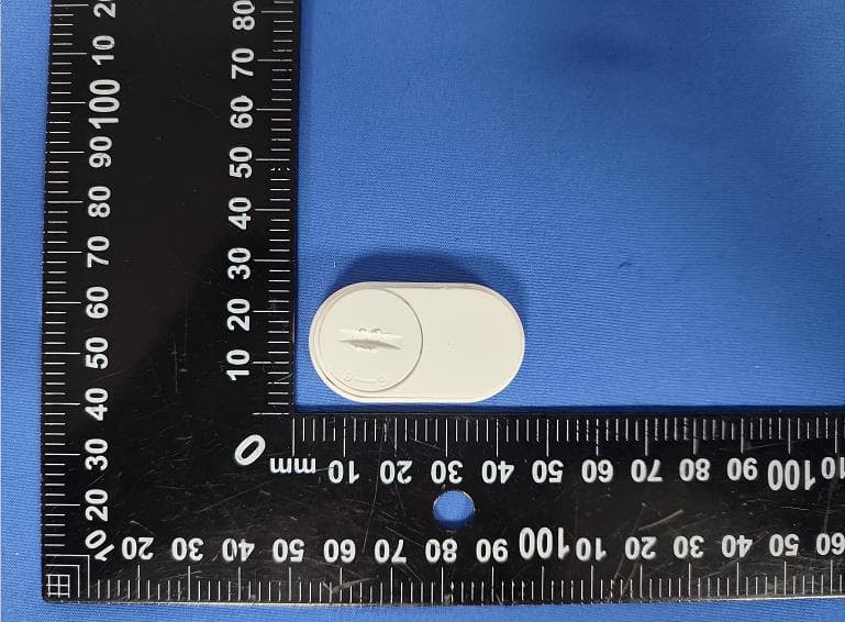
Click to zoom
Application Details
- Equipment Class
- DSS - Part 15 Spread Spectrum Transmitter
- Date of Grant
- Jul 24, 2024
- Application Purpose
- Original Equipment
- Date of Application
- Jul 22, 2024
- Equipment Note
- Bluetooth Magic Selfie stick
- Frequency Range
- 2402.00000000 - 2480.00000000
- Company
- Superior communications .
- Country
- United States
Documents & Files
Document Text
Text extracted from the exhibit documents filed with the FCC. Open a document above to read the original.
Users Manual
Connecting / Bluetooth Pairing 1.Make sure the PureGear Magnetic Selfie Stick Tripod Stand remote is within 2-3 ft (0.6-0.9m) of the device you will be connecting to. 2.Turn on your device’s Bluetooth. Most devices will automatically detect your PureGear Magnetic Selfie Stick Tripod Stand remote. Locate and select “PG Selfie Stick”. If your device does not automatically detect your remote, make sure Bluetooth is turned on, do a SEARCH for “PG Selfie Stick” and then click CONNECT. Operating the PureGear Magnetic Selfie Stick Tripod Stand 1. Lift up the bracket. 2. For non-MagSafe phones, insert mobile phone into silicone holder. 3. For MagSafe phones, remove the silicone phone holder and attach directly to the magnetic ring. 4. To use tripod, open the base and extend the telescoping neck to the desired position. Note: If the support does not close completely, please press the upper area with your fingers to close. FCC Statement This device complies with part 15 of the FCC rules. Operation is subject to the following two conditions: (1) this device may not cause harmful interference, (2) this device must accept any interference received, including interference that may cause undesired operation. Warning: Changes or modifications not expressly approved by the party responsible for compliance could void the user’s authority to operate the equipment. NOTE: This equipment has been tested and found to comply with the limits for a Class B digital device, pursuant to part 15 of the FCC Rules. These limits are designed to provide reasonable protection against harmful interference in a residential installation. This equipment generates uses and can radiate radio frequency energy and, if not installed and used in accordance with the instructions, may cause harmful interference to radio communications. However, there is no guarantee that interference will not occur in a particular installation. If this equipment does cause harmful interference to radio or television reception, which can be determined by turning the equipment off and on, the user is encouraged to try to correct the Cumplimiento con la FCC Este dispositivo cumple con la Parte 15 de las reglas de la FCC. La operación está sujeta a las siguientes dos condiciones: (1) este dispositivo no puede causar interferencia dañina, y (2) este dispositivo deberá aceptar cualquier interferencia recibida, incluyendo interferencia que pudiera causar una operación indeseable. Advertencia: Los cambios o modificaciones a esta unidad que no estén expresamente aprobados por la parte responsable del cumplimiento podrían anular la autoridad del usuario para operar el equipo. NOTA: Este equipo ha sido probado y se encontró que cumple con los l ímites establecidos para un dispositivo digital Clase B, de conformidad con la sección 15 de las reglas de la FCC. Estos límites están diseñados para ofrecer protección razonable contra interferencias perjudiciales cuando el equipo se opere en una instalación residencial. Este equipo genera, usa y puede emitir energía de radio frecuencia, y si no se instala y usa de conformidad con las instrucciones podría provocar interferencia perjudicial en las comunicaciones de radio. Sin embargo, no se garantiza que dicha interferencia no ocurrirá en una instalación específica. Si este equipo genera interferencia perjudicial en la recepción de radio o televisión, lo cual se puede determinar apagando y encendiendo el equipo, se sugiere que el usuario intente corregir la interferencia mediante una o más de las siguientes medidas: • Mover o reorientar la antena receptora. • Aumentar la separación entre el equipo y el receptor. • Conectar el equipo a una salida o circuito distinto al que está conectado el receptor. • Consultar al proveedor o a un técnico de radio o televisión con experiencia para que le ayuden. El dispositivo ha sido evaluado para que cumpla con los requisitos generales de exposición a RF. El dispositivo se puede usar en condiciones de exposición portátil sin restricciones. FCC ID: YJW-11139PG interference by one or more of the following measures: • Reorient or relocate the receiving antenna. • Increase the separation between the equipment and receiver. • Connect the equipment into an outlet on a circuit different from that to which the receiver is connected. •Consult the dealer or an experienced radio/TV technician for help. The device has been evaluated to meet general RF exposure requirement. The device can be used in portable exposure condition without restriction. FCC ID: YJW-11139PG ENGLISH ESPAÑOL User Manual Manual del usuario Connecting / Bluetooth Pairing 1.Make sure the PureGear Magnetic Selfie Stick Tripod Stand remote is within 2-3 ft (0.6-0.9m) of the device you will be connecting to. 2.Turn on your device’s Bluetooth. Most devices will automatically detect your PureGear Magnetic Selfie Stick Tripod Stand remote. Locate and select “PureGear Selfie Stick”. If your device does not automatically detect your remote, make sure Bluetooth is turned on, do a SEARCH for “PureGear Selfie Stick” and then click CONNECT. Operating the PureGear Magnetic Selfie Stick Tripod Stand 1. Lift up the bracket. 2. For non-MagSafe phones, insert mobile phone into silicone holder. 3. For MagSafe phones, remove the silicone phone holder and attach directly to the magnetic ring. 4. To use tripod, open the base and extend the telescoping neck to the desired position. Note: If the support does not close completely, please press the upper area with your fingers to close. pure-gear.com © 2024 | F00230PG | 65028PG | 65029PG Magnetic Selfie Stick Tripod Stand Magnetic Selfie Stick Tripod Stand
Attestation Statements
C5266091_X24_Ed.2 1/1 “Attestation Statements” TO: Office of Engineering Technology Federal Communications Commission 7435 Oakland Mills Road Columbia, MD 21046 The Commission adopted rules that prohibit equipment authorization for “covered” telecommunications equipment and video surveillance equipment produced by entities identified on the Commission’s Covered List 1 , which is periodically updated. See the Covered List for more details. This Attestation Statement is to confirm that we follow the Section 2.911(d)(5)(i)-(ii) Applicant Company name: Superior Communications Grantee Code: YJW FCC ID: YJW-11139PG FRN: 0019944727 Contact Name: George Chen Address: 5027 4th Street, Irwindale, California. 91706 USA Telephone No: +1 626 388 2541 Fax No: / Email: [email protected] Product Name: Bluetooth Magic Selfie stick Model Number: 11139PG, 11140PG i. [Superior Communications] (“the applicant”) certifies that the equipment for which authorization is sought is not “covered” equipment prohibited from receiving an equipment authorization pursuant to section 2.903 of the FCC rules. The applicant must sign this certification. ii. [Superior Communications] (“the applicant”) certifies that, as of the date of the filing of the application, the applicant is not (as a specifically named entity or any of its subsidiaries or affiliates) identified on the Covered List as an entity producing “covered” equipment. The applicant must sign this certification. [Superior Communications] (“the applicant”) certifies that, as of the date of the filing of the application, the applicant is not identified on the Covered List as an entity producing “covered” equipment . Signature: July 18, 2024 Name George Chen Position VP Product Development Company Name Superior Communications Address 5027 4th Street, Irwindale, California. 91706 USA Tel +1 626 388 2541 Fax / Email [email protected] The Commission’s Covered List is published by the Public Safety and Homeland Security Bureau and posted on the Commission’s website. This Covered List, which is periodically updated, identifies particular equipment, produced by particular entities, that constitutes “covered” equipment. https://www.fcc.gov/supplychain/coveredlist
Attestation Statements
Superior communications. FCC ID: YJW-11139PG Product Similarity Declaration Product name: Bluetooth Magic Selfie stick Model name: 11139PG, 11140PG We (Superior communications.) hereby state: Their software parameters and hardware design (i.e. circuit design, PCB layout, RF module/circuit, antenna type and position, components on the PCB, etc.) are all the same. Signature: July 18, 2024 Name George.Chen Position VP Product Development Company Name Superior Communications Address 5027 4th Street, Irwindale, California. 91706 USA Tel +1 626 388 2541 Fax / Email [email protected]
Cover Letter(s)
C5266091_X8_Ed.1 1/1 Letter of Authorization Superior Communications Company name: Superior Communications Grantee Code: YJW FCC ID: YJW-11139PG FRN: 0019944727 Contact Name: George Chen Address: 5027 4th Street, Irwindale, California. 91706 USA Telephone No: +1 626 388 2541 Fax No: / Email: [email protected] Product Name: Bluetooth Magic Selfie stick Model Number: 11139PG, 11140PG We authorize LGAI Technological Center S.A., Ronda de la Font del Carme, s/n, 08193 Bellaterra, Spain, to act on our behalf on all matters concerning the above named equipment. Any individual within LGAI Technological Center S.A. is authorized to act on our behalf and take action on the application. We declare that authorize LGAI Technological Center S.A., Ronda de la Font del Carme, s/n, 08193 Bellaterra, Spain, is allowed to forward all information related to the approval project to the Federal Communication Commission and to discuss any issues concerning the approval application. Any and all acts carried out by LGAI Technological Center S.A. on our behalf shall have the same effect as acts of our own. Signature: July 18, 2024 Name George Chen Position VP Product Development Company Name Superior Communications Address 5027 4th Street, Irwindale, California. 91706 USA Tel +1 626 388 2541 Fax / Email [email protected]
Cover Letter(s)
C5266091_X10_Ed.2 1/1 Superior Communications Office of Engineering Technology Federal Communications Commission 7435 Oakland Mills Road Columbia, MD 21046 Date: 22 July 2024 Subject: Request for Confidentiality FCC ID: YJW-11139PG To Whom It May Concern, Pursuant to the provisions of Sections 0.457 and 0.459 of Commission's rules (47CFR0.457, 0.459), we are requesting the Commission to withhold the following attachment(s) as confidential document from public disclosure. Exhibits Long-Term Confidentiality Short-Term Confidentiality NOTE 2 ID Label/Location No No Attestation Statement No No External Photos No ☐ Block Diagram ☒ ☐ Schematics ☒ ☐ Test Report No No Test Setup Photos No ☐ User’s Manual ☐ NOTE 1 ☐ Internal Photos ☐ NOTE 1 ☐ Parts List / Tune Up ☐ ☐ RF Exposure Info No No Operational Description ☒ ☐ Cover Letter(s) No No SDR Software / Security Info No No NOTE 1: Long-Term Confidentiality may be permitted under special conditions (See II. LONG-TERM CONFIDENTIALITY, Section 3 of KDB 726920, use last in force) NOTE 2: Short-Term Confidentiality can be requested for a maximum of 180 days from the date of the grant. Above mentioned document contains detailed system and equipment description are considered as proprietary information in operation of the equipment. The public disclosure of above documents might be harmful to our company and would give competitor an unfair advantage in the market. In case of short-term Confidentiality, the applicant requests the exhibits selected above are withheld from public view for a period of ______ days from the date of the Grant of Equipment Authorization and prior to marketing. It is our understanding that all measurement test reports, FCC ID label format and correspondent during certification review process cannot be granted as confidential documents and those information will be available for public review once the grant of equipment authorization is issued. Sincerely, C5266091_X10_Ed.2 1/1 Signature: July 22, 2024 Name George Chen Position VP Product Development Company Name Superior Communications Address 5027 4th Street, Irwindale, California. 91706 USA Tel +1 626 388 2541 Fax / Email [email protected]
External Photos
Page 1 of 4 Report No.: psi2405062-C01-R01 Shenzhen PSI Testing Co., Ltd. Tel: 0755-23011775 | E-mail: [email protected] | http://www.psi-lab.com Add: 1-2/F., Building 5, Yudafu Industrial Park, No.10, Xingye West Road, Shajing Subdistrict, Bao'an District, Shenzhen, Guangdong, China Appendix II external photos FCC ID: YJW-11139PG Page 2 of 4 Report No.: psi2405062-C01-R01 Shenzhen PSI Testing Co., Ltd. Tel: 0755-23011775 | E-mail: [email protected] | http://www.psi-lab.com Add: 1-2/F., Building 5, Yudafu Industrial Park, No.10, Xingye West Road, Shajing Subdistrict, Bao'an District, Shenzhen, Guangdong, China Page 3 of 4 Report No.: psi2405062-C01-R01 Shenzhen PSI Testing Co., Ltd. Tel: 0755-23011775 | E-mail: [email protected] | http://www.psi-lab.com Add: 1-2/F., Building 5, Yudafu Industrial Park, No.10, Xingye West Road, Shajing Subdistrict, Bao'an District, Shenzhen, Guangdong, China Page 4 of 4 Report No.: psi2405062-C01-R01 Shenzhen PSI Testing Co., Ltd. Tel: 0755-23011775 | E-mail: [email protected] | http://www.psi-lab.com Add: 1-2/F., Building 5, Yudafu Industrial Park, No.10, Xingye West Road, Shajing Subdistrict, Bao'an District, Shenzhen, Guangdong, China ------End------
ID Label/Location Info
Label Location FCC ID: YJW-11139PG Model No.: 11139PG
Internal Photos
Page 1 of 3 Report No.: psi2405062-C01-R01 Shenzhen PSI Testing Co., Ltd. Tel: 0755-23011775 | E-mail: [email protected] | http://www.psi-lab.com Add: 1-2/F., Building 5, Yudafu Industrial Park, No.10, Xingye West Road, Shajing Subdistrict, Bao'an District, Shenzhen, Guangdong, China Appendix III internal photos FCC ID: YJW-11139PG Page 2 of 3 Report No.: psi2405062-C01-R01 Shenzhen PSI Testing Co., Ltd. Tel: 0755-23011775 | E-mail: [email protected] | http://www.psi-lab.com Add: 1-2/F., Building 5, Yudafu Industrial Park, No.10, Xingye West Road, Shajing Subdistrict, Bao'an District, Shenzhen, Guangdong, China Page 3 of 3 Report No.: psi2405062-C01-R01 Shenzhen PSI Testing Co., Ltd. Tel: 0755-23011775 | E-mail: [email protected] | http://www.psi-lab.com Add: 1-2/F., Building 5, Yudafu Industrial Park, No.10, Xingye West Road, Shajing Subdistrict, Bao'an District, Shenzhen, Guangdong, China ------End------ TX ANT
RF Exposure Info
FCC ID: YJW-11139PG Shenzhen PSI Testing Co., Ltd. Tel: 0755-23011775 | E-mail: [email protected] | http://www.psi-lab.com Add: 1-2/F., Building 5, Yudafu Industrial Park, No.10, Xingye West Road, Shajing Subdistrict, Bao'an District, Shenzhen, Guangdong, China RF Exposure evaluation According to 447498 D01 General RF Exposure Guidance v06 The 1-g and 10-g SAR test exclusion thresholds for 100 MHz to 6 GHz at test separation distances ≤ 50 mm are determined by: [(max. power of channel, including tune-up tolerance, mW)/(min. test separation distance, mm)] ·[√f(GHz)] ≤ 3.0 for 1-g SAR and ≤ 7.5 for 10-g extremity SAR, where f(GHz) is the RF channel transmit frequency in GHz Power and distance are rounded to the nearest mW and mm before calculation The result is rounded to one decimal place for comparison EDR Worse case output power is as below: [2480MHz: 2.94dBm] Antenna Gain is 2.3dBi Maximum output power is 5.24dBm (3.34mW). (3.34mW /5mm)·[√2.480(GHz)]= 1.05<3.0 for 1-g SAR Then SAR evaluation is not required
Test Report
Shenzhen PSI Testing Co., Ltd. Tel: 0755-23011775 | E-mail: [email protected] | http://www.psi-lab.com Add: 1-2F, Building 5, Yudafu Industrial Park, No. 10, Xingye West Road, Shajing Street, Bao’an District, Shenzhen, Guangdong, China 518104 FCC TEST REPORT FCC ID: YJW-11139PG On Behalf of Superior communications. Bluetooth Magic Selfie stick Model No.: 11139PG, 11140PG Prepared for : Superior communications. Address : 5027 Irwindale Ave.Suite Prepared By : Shenzhen PSI Testing Co., Ltd. Address : 1-2/F., Building 5, Yudafu Industrial Park, No.10, Xingye West Road, Shajing Subdistrict, Bao’an District, Shenzhen, Guangdong, China Report Number : psi2405062-C01-R01 Date of Receipt : May 15, 2024 Date of Test : May 15, 2024- May 25, 2024 Date of Report : May 25, 2024 Version Number : V0 Page 2 of 43 Report No.: psi2405062-C01-R01 Shenzhen PSI Testing Co., Ltd. Tel: 0755-23011775 | E-mail: [email protected] | http://www.psi-lab.com Add: 1&2F, Building 5, Yudafu Industrial Park, No. 10, Xingye West Road, Shajing Street, Bao'an District, Shenzhen, Guangdong, China 518104 TABLE OF CONTENTS Description Page 1. Summary Of Standards And Results ........................................................................................ 6 1.1. Description of Standards and Results.................................................................................. 6 2. General Information .................................................................................................................. 7 2.1. Description of Device (EUT) ................................................................................................ 7 2.2. Accessories of Device (EUT) .............................................................................................. 8 2.3. Tested Supporting System Details....................................................................................... 8 2.4. Block Diagram of connection between EUT and simulators ................................................. 8 2.5. Test Mode Description ........................................................................................................ 8 2.6. Test Conditions ................................................................................................................... 9 2.7. Test Facility ........................................................................................................................ 9 2.8. Measurement Uncertainty ................................................................................................... 9 2.9. Test Equipment List .......................................................................................................... 10 3. Maximum Peak Output Power ..................................................................................................11 3.1. Limit ..................................................................................................................................11 3.2. Test Procedure ..................................................................................................................11 3.3. Test Setup .........................................................................................................................11 3.4. Test Result ........................................................................................................................11 4. Bandwidth .................................................................................................................................12 4.1. Limit ................................................................................................................................. 12 4.2. Test Procedure ................................................................................................................. 12 4.3. Test Result ....................................................................................................................... 12 5. Carrier Frequency Separation ..................................................................................................17 5.1. Limit ................................................................................................................................. 17 5.2. Test Procedure ................................................................................................................. 17 5.3. Test Result ....................................................................................................................... 17 6. Number Of Hopping Channel ...................................................................................................18 6.1. Limit ................................................................................................................................. 18 6.2. Test Procedure ................................................................................................................. 18 6.3. Test Result ....................................................................................................................... 18 7. Dwell Time ................................................................................................................................19 7.1. Test limit ........................................................................................................................... 19 7.2. Test Procedure ................................................................................................................. 19 7.3. Test Result ....................................................................................................................... 19 8. Out-of-band Emissions ............................................................................................................23 8.1. Test Limits ........................................................................................................................ 23 8.2. Test Procedure ................................................................................…
Text truncated - open the document above for the full version.
Test Report
1. Antenna Description: Antenna plate Monopole Antenna Antenna peak gain 2.3 dBi Frequency range 2.402MHz~2.480MHz Connect type Direct Connect 2. Picture of antenna 3. Radiation pattern @2.402GHz FCC ID:YJW-11139PG Model:11139PG Manufacturer:WINNERS’SUN PLASTIC ELECTRONIC(SHENZHEN)CO.,LTD Address:2 Bldg Detai Industrial Zone ,Huarong Rd Longhua Dist ShenZhen GuangDong Province 2402MHz Z-Y Plane 2402MHz Radiation pattern @2.441GHz 2480MHz Radiation pattern @2.480GHz Z-Y Plane 2480MHz
Test Setup Photos
Page 1 of 1 Report No.: psi2405062-C01-R01 Shenzhen PSI Testing Co., Ltd. Tel: 0755-23011775 | E-mail: [email protected] | http://www.psi-lab.com Add: 1-2/F., Building 5, Yudafu Industrial Park, No.10, Xingye West Road, Shajing Subdistrict, Bao'an District, Shenzhen, Guangdong, China Appendix I Test Setup Photo FCC ID: YJW-11139PG Spurious Radiation Emissions Test (<1G) Spurious Radiation Emissions Test (>1G) ------End------
Contact Information
Applicant
George Chen(VP Product Development)
Technical Contact
Superior CommunicationsGeorge Chen
[email protected]+1 626 388 2541
Irwindale, California · United States
Test Firm
Shenzhen PSI Testing Co., Ltd.Simple Guan
[email protected]+86 0755-23019820
Technical Specifications
| # | Rule Parts | Frequency Range | Power Output |
|---|---|---|---|
| 1 | 15C | 2.40 GHz - 2.48 GHz | 1.97 mW |
Other Applications from Superior communications .

YJW-12572PL
Sep 10, 2026Power bank
Equipment Class
DCD - Part 15 Low Power Transmitter Below 1705 kHz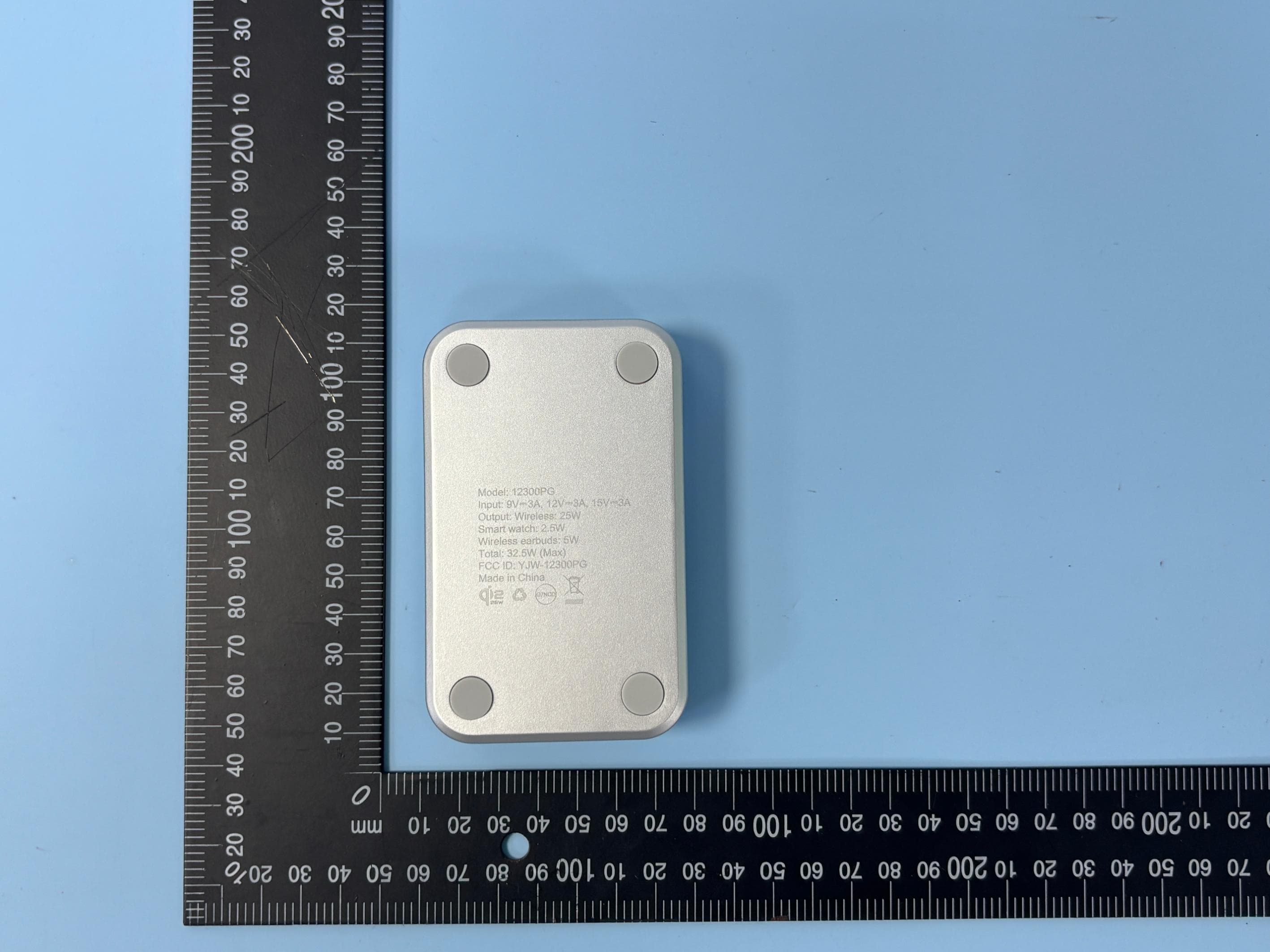
YJW-12300PG
Aug 17, 2026PureGear Universal Cradle Vent Mount
Equipment Class
DCD - Part 15 Low Power Transmitter Below 1705 kHz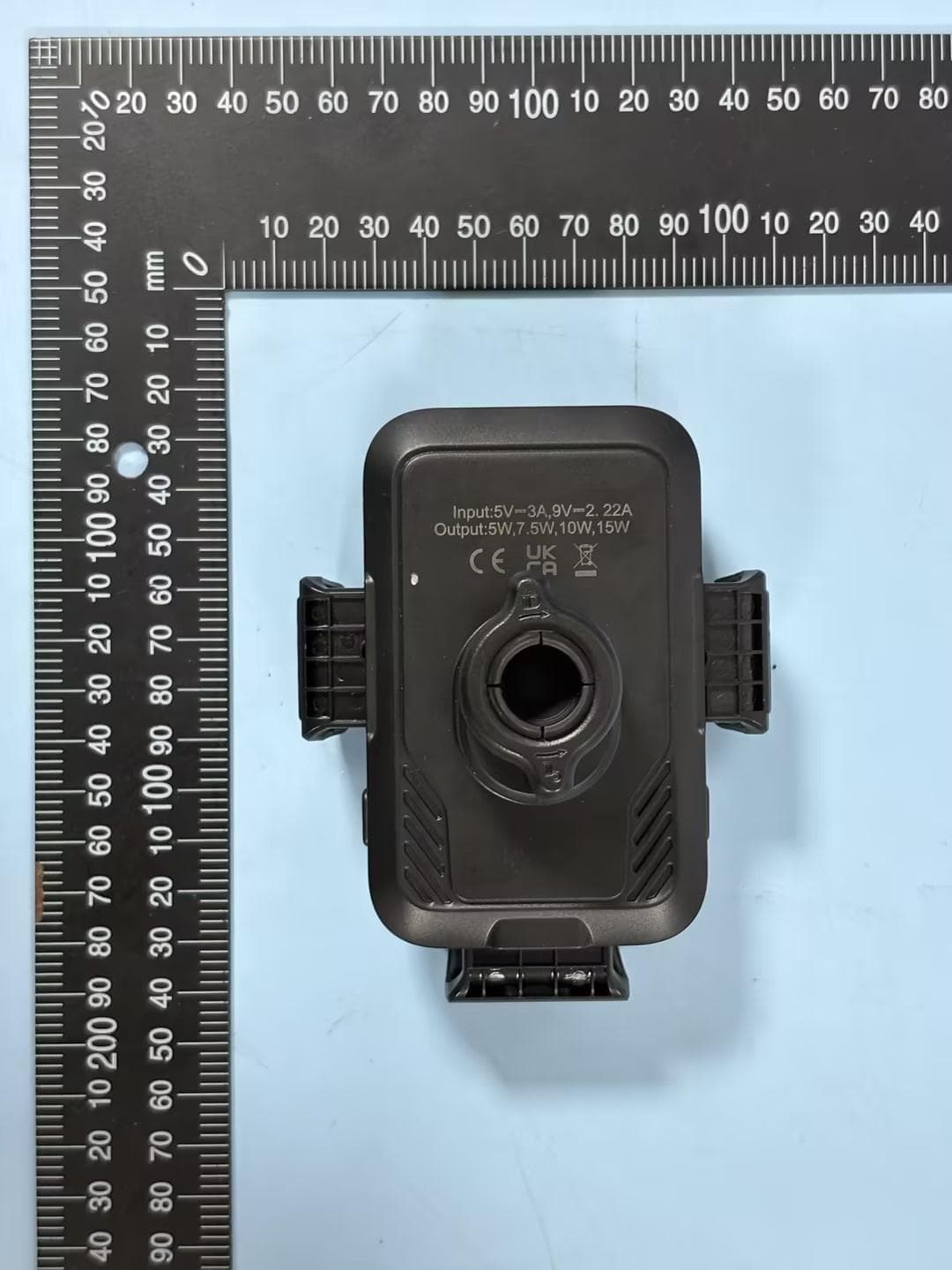
YJW-12338PG
Jul 13, 2026PureGear Universal Cradle Vent Wireless Charger
Equipment Class
DCD - Part 15 Low Power Transmitter Below 1705 kHz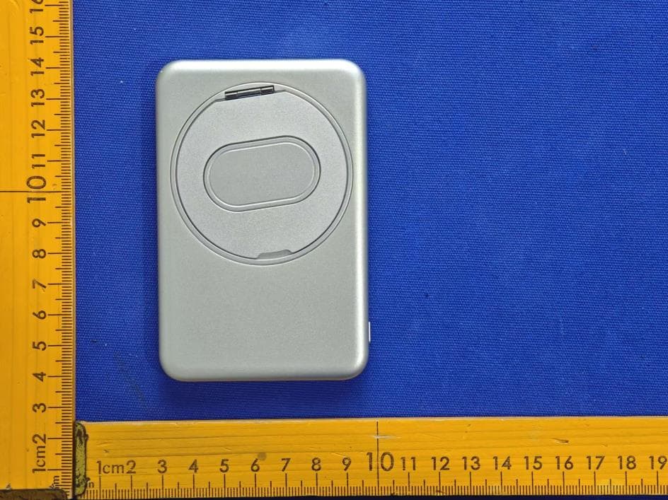
YJW-12196PG
Feb 07, 2026Magnetic Wireless Charging Power Bank
Equipment Class
DCD - Part 15 Low Power Transmitter Below 1705 kHz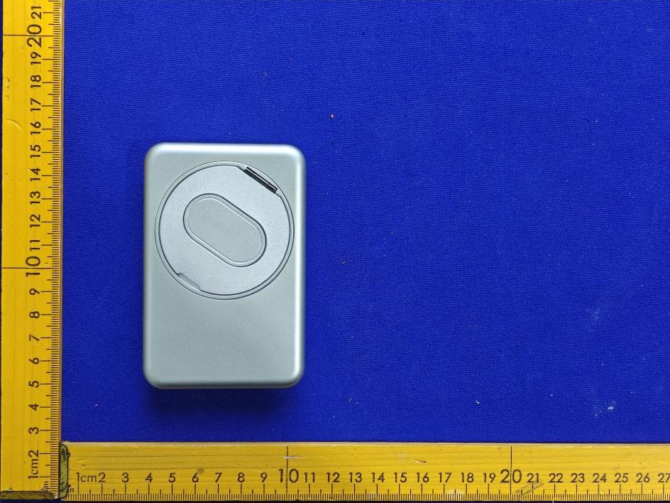
YJW-12197PG
Feb 07, 2026Magnetic Wireless Charging Power Bank
Equipment Class
DCD - Part 15 Low Power Transmitter Below 1705 kHz