YLKPT2CELECTRONIC LEVERSET
Tong Lung Metal Industry Co.,Ltd.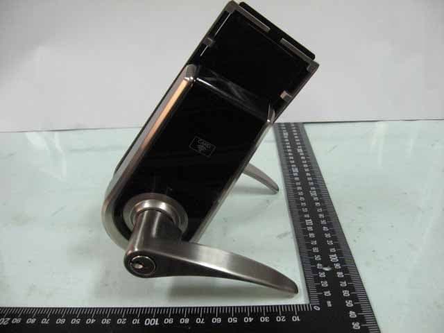
Click to zoom
Application Details
- Equipment Class
- DXX - Part 15 Low Power Communication Device Transmitter
- Date of Grant
- May 11, 2013
- Application Purpose
- Original Equipment
- Date of Application
- May 11, 2013
- Equipment Note
- ELECTRONIC LEVERSET
- Frequency Range
- 13.56000000 - 13.56000000
- Country
- Taiwan
Documents & Files
Document Text
Text extracted from the exhibit documents filed with the FCC. Open a document above to read the original.
Users Manual
CARD CARD card Instruction : After the setup is complete, place the card close to the sensor (when it beeps once, the registration is complete). The number “1” above represents the order of the card. If the card to be registered is the third card, enter the number “3”, and so on. A maximum of 6 cards can be registered. They can be registered individually or consecutively. 131 2. Voiding designated cards Instruction : The number “1” above represents the order of the card. To void the cards, please enter the order of the card. For example, if the third card is to be voided, enter “3”, and so on. The cards may be voided individually or consecutively. 3. Voiding all cards at the same time 141 15 Instruction : When it beeps twice, all cards have been voided. SETUP 1. Register the card 1-1 All cards have been registered in the factory. 1-2 The master password must be entered for the registration. The cards may be registered individually or consecutively with a maximum of 6 cards. 2. Void designated card 2-1 The master password is required to void the card. Voided cards may be reused again after registration. 2-2 The cards may be voided individually or consecutively. 3. Void all cards at the same time 3-1 The master password is required to void the cards. 3-2 All cards may be voided at the same time. The voided cards may be reuse again after registration. ELECTRONIC KEYPAD LOCK INSTRUCTION MANUAL FOR PROXIMITY CARD Notice : The changes or modifications not expressly approved by the party responsible for compliance could void the user's authority to operate the equipment. IMPORTANT NOTE : To comply with the FCC RF exposure compliance requirements, no change to the antenna or the device is permitted. Any change to the antenna or the device could result in the device exceeding the RF exposure requirements and void user's authority to operate the device. This device complies with Part 15 of the FCC Rules. Operation is subject to the following two conditions : (1) this device may not cause harmful interference, and (2) this device must accept any interference received, including interference that may cause undesired operation. REGISTRATION 1. Registering the cards Enter PC Enter PC Enter PC 45 40 35 1-3/4" 1-9/16" 1-3/8" 2" 51 120x165(mm) Product : Purchase Date : DIGITAL TOUCHPAD LEVER LOCK Limited Warranty Statements 1. Warranty The manufacturer warrants the Product to be free from defects in material and workmanship for a period of 12 months from the original date of purchase. If you discover a defect in the Product covered by this warranty, we will repair or replace the item at our option using new or refurbished components. 2. Exclusions This warranty covers defects in manufacturing discovered while using the Products as recommended by The manufacturer rather than occurred by the act of God, and damages caused by misuse, abuse, and unauthorized modification. 3. Limited of Liability The manufacturer will not be held liable for incidental or consequential losses or damages to any act of God. 4. Reminder Service requirement shall subject to the presentation of this warranty card and defective parts to the manufacturer. The warranty card will not be reissued if lost. TEMPLA TE Mark Ø 1" (25.4mm) hole at center of door edge. Ø ( ) 2-1/8" 54mm Fit here on door edge FOR ( ) 2-3/4” 70mm BACKSET FOR ( ) 2-3/8” 60mm BACKSET USER MANUAL Attention : Please do not use the "electronic" screwdriver for installation. ELECTRONIC KEYPAD LOCK This device complies with Part 15 of the FCC Rules. Operation is subject to the following two conditions : (1) this device may not cause harmful interference, and (2) this device must accept any interference received, including interference that may cause undesired operation. ■ ̇ ̇ ̇ ■ ■ ■ ̇ ̇ ̇ ̇ ̇ ̇ ̇ ̇ ̇ ̇ ̇ ̇ ̇ ̇ ̇ ̇ ■ ■ ■ ■ Installation Instructions ..................................P.1 Replace the old lock with the new one Install the new lock on the new door Starting the installation ..................................P.4 Operation Interface .........................................P.7 Specifications and Functions ........................P.8 Code Setup .....................................................P.11 Notifications ...................................................P.11 Function Setup ..............................................P.12 Troubleshooting ............................................P.14 Indentifying the door handing Power supply Low battery indication Keypad light indication Audio indication Programming Code (PC) User Code (UC) Delete individual user code Delete all user codes at once Invalidate user codes temporarily Create the one-time user code Restore default PC & UC Unlock Lock Automatic lock Password protection function Backlit function Table of Contents P.1 P.1 P.2 P.8 P.8 P.8 P.8 P.8 P.9 P.9 P.9 P.9 P.9 P.9 P.10 P.10 P.10 P.10 P.10 12 The distance between the edge of the door to the center of the hole is the latch backset. The adjustable latch provides two choices of backsets 2-3/8" (60mm) and 2-3/4" (70mm). Change the backset for the latch according to the illustration. For adjustments please refer to the following illustrations. Note : The correct direction for the cam is shown as the circle on the left side. a c b Latch face plate Prior to installation, please make sure that the face plate is appropriate for the latch. Drive-in latch Installation of the round face plate Replace the old lock with the new one To replace the old lock with this product on the same door, please confirm the backset for the latch and the specifications for the face plate match. Please also refer to the following instructions to adjust the backset and face plate to match the existing door's specifications. Install new lock on the new door To install this product on a new door, please go through the following steps to drill the hole. Check that the lever direction meets the door handing. If not, please switch the levers by following steps. ■Installation Instructio…
Text truncated - open the document above for the full version.
External Photos
ETC Report No.:13-01-RBF-018-01 Sheet 1 of 7 Sheets FCC ID.: YLKPT2C Rev. No 1.0 CONSTRUCTED PHOTOS of EUT (A)EUT 1. 2. ETC Report No.:13-01-RBF-018-01 Sheet 2 of 7 Sheets FCC ID.: YLKPT2C Rev. No 1.0 CONSTRUCTED PHOTOS of EUT 3. 4. ETC Report No.:13-01-RBF-018-01 Sheet 3 of 7 Sheets FCC ID.: YLKPT2C Rev. No 1.0 CONSTRUCTED PHOTOS of EUT 5. 6.
ID Label/Location Info
910805 1 LABEL 45mm 30mm Model :PT2C FCC ID : YLKPT2C This device complies with Part 15 of the FCC Rules. Operation is subject to the following two conditions: (1) this device may not cause harmful interference, and (2) this device must accept any interference received, including interference that may cause undesired operation.
Internal Photos
ETC Report No.:13-01-RBF-018-01 Sheet 4 of 7 Sheets FCC ID.: YLKPT2C Rev. No 1.0 CONSTRUCTED PHOTOS of EUT 7. 8. ETC Report No.:13-01-RBF-018-01 Sheet 5 of 7 Sheets FCC ID.: YLKPT2C Rev. No 1.0 CONSTRUCTED PHOTOS of EUT 9. 10. ETC Report No.:13-01-RBF-018-01 Sheet 6 of 7 Sheets FCC ID.: YLKPT2C Rev. No 1.0 CONSTRUCTED PHOTOS of EUT 11. 12. ETC Report No.:13-01-RBF-018-01 Sheet 7 of 7 Sheets FCC ID.: YLKPT2C Rev. No 1.0 CONSTRUCTED PHOTOS of EUT 13. 14.
Test Report
Rev. No 1.0 FCC Part 15 EMI TEST REPORT of E.U.T. : ELECTRONIC LEVERSET FCC ID. : YLKPT2C Model : PT2C Working Frequency : 13.56 MHz for APPLICANT : Tong Lung Metal Industry Co., Ltd ADDRESS : 62, Chung-Hsiao 1st Street, Hou-Hu-Li, Chia-Yi 600, Taiwan, R.O.C. Test Performed by ELECTRONICS TESTING CENTER, TAIWAN NO. 34, LIN 5, DING FU TSUN, LINKOU HSIANG TAIPEI HSIEN, TAIWAN, R.O.C. Tel : (02)26023052 Fax : (02)26010910 http://www.etc.org.tw ; e-mail : [email protected] Report Number : 13-01-RBF-018-01 ETC Report No.:13-01-RBF-018-01 FCC ID.: YLKPT2C Rev. No 1.0 TEST REPORT CERTIFICATION Applicant : Tong Lung Metal Industry Co., Ltd 62, Chung-Hsiao 1st Street, Hou-Hu-Li, Chia-Yi 600, Taiwan, R.O.C. Manufacture : Tong Lung Metal Industry Co., Ltd 62, Chung-Hsiao 1st Street, Hou-Hu-Li, Chia-Yi 600, Taiwan, R.O.C. Description of EUT : a) Type of EUT : ELECTRONIC LEVERSET b) Trade Name : EZSET,EZSET,KWIKSET c) Model No. : PT2C d) FCC ID : YLKPT2C e) Working Frequency : 13.56 MHz f) Power Supply : DC 1.5V Battery * 4 Regulation Applied : FCC Rules and Regulations Part 15 Subpart C I HEREBY CERTIFY THAT; The data shown in this report were made in accordance with the procedures given in ANSI C63.4 and the energy emitted by the device was founded to be within the limits applicable. I assume full responsibility for accuracy and completeness of these data. Note : 1. The results of the testing report relate only to the items tested. 2. The testing report shall not be reproduced except in full, without the written approval of ETC Issued Date : Apr. 03, 2013 Test Engineer : (Vincent Chang) Approve & Authorized Signer : S. S. Liou, Section Manager EMC Dept. II of ELECTRONICS TESTING CENTER, TAIWAN ETC Report No.:13-01-RBF-018-01 FCC ID.: YLKPT2C Rev. No 1.0 Table of Contents Page 1. GENERAL INFORMATION ............................................................................................................................... 1 1.1 PRODUCT DESCRIPTION................................................................................................................................... 1 1.2 CHARACTERISTICS OF DEVICE:................................................................................................................................ 1 1.3 TEST METHODOLOGY.............................................................................................................................................. 1 1.4 TEST FACILITY........................................................................................................................................................ 1 2. DEFINITION AND LIMITS ................................................................................................................................ 2 2.1 DEFINITION............................................................................................................................................................. 2 2.2 RESTRICTED BANDS OF OPERATION........................................................................................................................ 2 2.3 LIMITATION............................................................................................................................................................. 2 2.4 LABELING REQUIREMENT........................................................................................................................................ 4 2.5 USER INFORMATION................................................................................................................................................ 4 3 SYSTEM TEST CONFIGURATION ................................................................................................................... 5 3.1 JUSTIFICATION........................................................................................................................................................ 5 3.2 DEVICES FOR TESTED SYSTEM................................................................................................................................5 4. RADIATED EMISSION MEASUREMENT ...................................................................................................... 6 4.1 APPLICABLE STANDARD.......................................................................................................................................... 6 4.2 MEASUREMENT PROCEDURE................................................................................................................................... 6 4.3 TEST DATA.............................................................................................................................................................. 8 4.3.1 Below 30MHz .................................................................................................................................................. 8 4.3.2 30MHz – 1GHz................................................................................................................................................ 9 4.4 FIELD STRENGTH CALCULATION........................................................................................................................... 11 4.5 RADIATED TEST EQUIPMENT.................................................................................................................................. 11 4.8 MEASURING INSTRUMENT SETUP.......................................................................................................................... 11 4.9 RADIATED MEASUREMENT PHOTOS...................................................................................................................... 12 5 FREQUENCY STABILITY MEASUREMENT................................................................................................ 13 5.1 PROVISIONS APPLICABLE...................................................................................................................................... 13 5.2 MEASUREMENT PROCEDURE.................…
Text truncated - open the document above for the full version.
Test Setup Photos
ETC Report No.:13-01-RBF-018-01 Sheet 12 of 17 Sheets FCC ID.: YLKPT2C Rev. No 1.0 4.9 Radiated Measurement Photos
Contact Information
Applicant
Vincent Hsu(Q.C. Engineer)
Test Firm
Electronics Testing Center, TaiwanWill Yauo
Technical Specifications
| # | Rule Parts | Frequency Range | Power Output |
|---|---|---|---|
| 1 | 15C | 13.56 MHz - 13.56 MHz | - |
Other Applications from Tong Lung Metal Industry Co.,Ltd.

YLK-PLD-BT
Aug 16, 2020Electronic Touch Screen BLE Deadbolt
Equipment Class
DTS - Digital Transmission System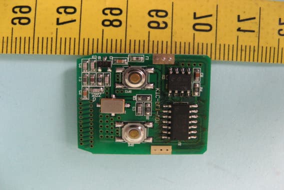
YLKPL1
Oct 04, 2010KKEYPAD ELECTRONIC DEDBOLT LOCK
Equipment Class
DSC - Part 15 Security/Remote Control Transmitter