YNE-000081-001Landscape Smart Transformer
Kichler Lighting LLC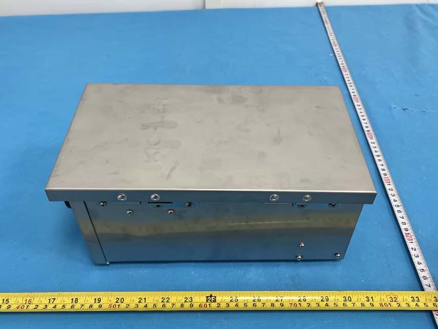
Click to zoom
Application Details
- Equipment Class
- DTS - Digital Transmission System
- Date of Grant
- Jun 05, 2023
- Application Purpose
- Original Equipment
- Date of Application
- Jun 05, 2023
- Equipment Note
- Landscape Smart Transformer
- Frequency Range
- 2412.00000000 - 2462.00000000
- Company
- Kichler Lighting LLC
- Country
- United States
Documents & Files
Document Text
Text extracted from the exhibit documents filed with the FCC. Open a document above to read the original.
Users Manual
For warranty information please visit: kichler.com/warranty IS-15SCT300SS-USREV 3-MAR-2023 We’re here to help 866-558-5706 Hrs: M-F 9am to 5pm EST CAUTIONS • CAUTION – RISK OF SHOCK: Disconnect Power at the main circuit breaker panel or main fusebox before starting and during the installation. • WARNING: This power supply is intended for installation in accordance with the National Electrical Code (NEC) and all local code specifications. If you are not familiar with code requirements, installation by a certified electrician is recommended. Failure to adhere to these codes and instructions may result in serious injury and/or property damage and will void the warranty. • This power unit is for use only with low voltage landscape luminaires and fittings. This device is accepted as a component of a landscape lighting system where the suitability of the combination shall be determined by the National Electric Code, by CSA, or by local inspection authorities having jurisdiction. • Do not energize power supply until installation of system is complete. • This power supply shall be connected to 120 volt, 60 Hz. • WARNING: Risk of Electric Shock, use only with low voltage landscape fixtures and accessories. Do not use with swimming pool or spa lighting fixtures. • Do not submerge power supply. • Do not connect two or more power supplies in parallel. • Not for use with dimmers. • Power supply should be mounted close to power source. Do not use extension cord. • Suitable for indoor or outdoor use in the USA. Suitable for outdoor use only in Canada. • For use in dwellings only with provided conduit adapter plate. • WARNING: To reduce the risk of electric shock, install only on a circuit protected by a GFCI. The minimum mounting distance from a pool, spa, or fountain is: o For indoor installation: 10 feet (3.0 m) o For outdoor installation: 5 feet (1.5 m) • The power unit shall be mounted at least a (minimum) of 1 foot (30 cm) above the ground. • National Electrical Code requires that wiring where concealed or extended through a building wall must be enclosed in conduit. • WARNING – Risk of Fire. If installation involves running wire through a building structure, special wiring methods are needed. Consult a qualified electrician. • Risk of fire, do not place insulation under terminal plate. Check connection after installation. • The cover must be closed while power supply is in use. • Direct burial rated wire is to be buried a minimum of 6” (152 mm) beneath the surface of the ground. • NOTE: If additional Direct Burial wire is needed, contact your local Kichler® landscape distributor. See table below for SPT 2 Conductor Black PVC Insulation Direct Burial wire accessories. 1. Determine desired location for mounting transformer. NOTE: When deciding location for mounting, consideration should be taken for the requirements listed in the “CAUTIONS” section of this instruction guide. If mounting to a drywall surface, mounting into a stud is recommended. 2. Hold template in place against mounting surface, and mark screw positions in top portion of keyhole slot [A] at top, and in slot [B] located at bottom. INSTALLATION INSTRUCTIONS This instruction sheet covers the installation of the following Kichler® Smart Connect Transformer: 15SCT300SS Read these instructions carefully before installing this unit and retain the instructions for future use. o For more information on voltage drop and wire gage selection, consult the Kichler Landscape Lighting Catalog or contact your local Kichler distributor. • Low-voltage transformers are devices that reduce a higher input voltage to a lower output voltage. The Kichler Low voltage transformer operates at 15 volts AC. To properly size the Landscape transformer requires creating a power requirement budget. Determine your installation plan and the fixtures that will be used. Reference the fixture wattage and consider the effects of power line gauge and run length to determine power budget requirements for the installation. • Finding Power Supply Load. To determine the power supply rating you will need, add up the wattages of all lamps you plan to use. Select a power supply that matches as closely as possible to the total lamp wattage. For example, if you have 14 fixtures all rated at 17VA, you will need a 300-watt (VA) power supply (14 x 17 = 238 VA). The total lamp load should not exceed its maximum wattage capacity. If your total wattage is too high, either divide the load between two power supplies, or use a power supply with a higher rating. • The power supply has three independently controlled zones. The channels include three Commons and three 15V taps. The zones are separated by divider [F]. The power supply has the ability to deliver full output load on one channel or distributed across all channels. • CLEANING: • Always be certain that electric current is turned off before cleaning. • Only a soft damp cloth should be used. Harsh cleaning products may damage the finish. Direct Burial 2 Conductor SPT Cable Wire GageLength (feet)Length (m)Model Number 10 AWG2507615504BK 12 AWG1003015501BK 12 AWG2507615502BK 12 AWG50015215505BK 12 AWG100030415506BK 3. If mounting to wood: • Drill 1/8” (3 mm) diameter pilot holes at positions marked in Step 2. • Drive screws [C] approximately halfway into holes. If mounting to 5/8” drywall (not into stud): • Drill 3/8”(9 mm) diameter holes at positions marked in Step 2. • Push plastic anchors [D] into holes and carefully tap in until flush with mounting surface. • Drive screws [C] approximately halfway into plastic anchors. 4. Slip large portion of keyhole [A] over head of top screw [C] and allow transformer to slide down, making sure bottom slot [B] is behind head of bottom screw [C]. 5. While holding transformer in place, tighten screws until transformer is secure. INSTALLATION INSTRUCTIONS CONTINUE ON PAGE 2 PAGE 1 KEYHOLE SLOT SLOT SCREWS [C] PLASTIC ANCHORS [D] PILOT DRILL HOLE • WOOD: 1/8” (3 mm) DRILL • DRYWALL: 3/8” (9 mm) DRILL…
Text truncated - open the document above for the full version.
Attestation Statements
Kichler Lighting LLC Add: 30455 Solon Road Solon, Ohio 44139, United States Tel: 216.573.1005 Extension:6520 Email: [email protected] Signature: Contact Person: John Noble Title : Lead Certification Engineer Attestation letter FEDERAL COMMUNICATIONS COMMISSION Authorization and Evaluation Division 7435 Oakland Mills Road Columbia, MD 21046 Date: 2023-05-22 To whom it may concern Dear Sir/Madam, We, Kichler Lighting LLC, hereby authorize China Certification ICT Co., Ltd ( Dongguan) to act as a laboratory for testing and test report generation for the following project(s): ( Product name: Landscape Smart Transformer, Model name: 15SCT300SS, FCC ID: YNE-000081-001) The B K7231N supports BT, BLE , WIFI Mode, But for this device, only WiFi 2412-2462 MHz(802.11b/g/n ht20),2422-2452MHz(802.11n ht40) and BLE 1M activated. Other function was disable by software. Sincerely,
Attestation Statements
Kichler Lighting LLC Add: 30455 Solon Road Solon, Ohio 44139, United States Tel: 216.573.1005 Extension:6520 Email: [email protected] Attestation Letter Date: 2023-05-22 FEDERAL COMMUNICATIONS COMMISSIONS Authorization and Evaluation Division 7435 Oakland Mills Road Columbia, MD 21046 Ref: Attestation Statements CFR 47 §2.911(d)(5)(i)(ii) Filing FCC ID: YNE-000081-001 Kichler Lighting LLC (“the applicant”) certifies that the equipment for which authorization is sought is not “covered” equipment prohibited from receiving an equipment authorization pursuant to section 2.903 of the FCC rules. Kichler Lighting LLC (“the applicant”) certifies that as of the date of the filing of the application, the applicant is not identified on the Covered List as an entity producing “covered” equipment. Sincerely, Signature Contact Person: John Noble Title: Lead Certification Engineer Company Name& Address: Kichler Lighting LLC Add: 30455 Solon Road Solon, Ohio 44139, United States CFR 47 §2.911(d)(5)(i)(ii) Attestation Letter
Attestation Statements
Kichler Lighting LLC Add: 30455 Solon Road Solon, Ohio 44139, United States Tel: 216.573.1005 Extension:6520 Email: [email protected] Attestation Letter for Agent Date: 2023-05-22 FEDERAL COMMUNICATIONS COMMISSIONS Authorization and Evaluation Division 7435 Oakland Mills Road Columbia, MD 21046 Ref: Attestation Statements Part 2.911 (d)(7) Filing FCC ID: YNE-000081-001 Kichler Lighting LLC certifies that, as of the date of the filing of the application, Kichler Lighting LLC is our designated U.S. agent for service of process for the above referenced . Kichler Lighting LLC agrees to maintain an agent for no less than one year after the grantee has terminated all marketing and importation or the conclusion of any Commission- related proceeding involving the equipment. Kichler Lighting LLC accepts, as of the date of the filing of the application, the obligation of the designated U.S. agent for service of process for the above referenced FCC ID. Designated U.S. Agent Information: Company name: Kichler Lighting LLC Address: 30455 Solon Road Solon, Ohio 44139, United States FRN: 0019876457 Contact person: John Noble Tel: 216.573.1005 Extension:6520 Email: [email protected] Sincerely,
Cover Letter(s)
Kichler Lighting LLC Add: 30455 Solon Road Solon, Ohio 44139, United States Tel: 216.573.1005 Extension:6520 Email: [email protected] FCC Authorization Date: 2023-05-22 FEDERAL COMMUNICATIONS COMMISSIONS Authorization and Evaluation Division 7435 Oakland Mills Road Columbia, MD 21046 Subject: Agent Authorization To whom it may concern: We, Kichler Lighting LLC, hereby authorize China Certification ICT Co., Ltd (Dongguan) to act on our behalf in all matters relating to application for Equipment authorization, including the signing of all documents relating to these matters. All acts carried out by China Certification ICT Co., Ltd (Dongguan) on our behalf shall have the same effect as our own action. We, the undersigned, hereby certify that we are not subject to a denial of federal benefits, that includes FCC benefits, pursuant to Section 5301 of the Anti-Drug Abuse Act of 1988, 21 U.S.C. 862. This authorization is valid until further written notice from the applicant. Sincerely yours, Contact Person: John Noble Title: Lead Certification Engineer Company Name& Address: Kichler Lighting LLC Add: 30455 Solon Road Solon, Ohio 44139, United States QA-FR-170-B
Cover Letter(s)
Kichler Lighting LLC Add: 30455 Solon Road Solon, Ohio 44139, United States Tel: 216.573.1005 Extension:6520 Email: [email protected] FCC Confidential Authorization Date: 2023-05-22 FEDERAL COMMUNICATIONS COMMISSION Authorization and Evaluation Division 7435 Oakland Mills Road Columbia, MD 21046 Subject: Confidentiality Request regarding application for certification of FCC ID: YNE-000081-001 In accordance with Sections 0.457 and 0.459 of the Commission’s Rules, (Kichler Lighting LLC) hereby requests long-term confidential treatment of information accompanying this application as outlined below: Block Diagram Schematics Operation Description The above materials contain proprietary and confidential information not customarily released to the public. The public disclosure of these materials provides unjustified benefits to its competitors in the market. Sincerely, Contact Person: John Noble Title: Lead Certification Engineer Company Name& Address: Kichler Lighting LLC Add: 30455 Solon Road Solon, Ohio 44139, United States QA-FR-171-A
External Photos
EXHIBIT B - EUT EXTERNAL PHOTOGRAPHS
Internal Photos
EXHIBIT C - EUT INTERNAL PHOTOGRAPHS uncover chip chip chip Antenna
RF Exposure Info
China Certification ICT Co., Ltd (Dongguan) Report No.: CR221264137-00A Page 43 of 43 5. RF EXPOSURE EVALUATION 5.1 Applicable Standard FCC §15.247 (i) and subpart §1.1307 Systems operating under the provisions of this section shall be operated in a manner that ensures that the public is not exposed to radio frequency energy level in excess of the Commission’s guidelines. 5. 2 Procedure According to §1.1307(b)(3)(i) (C) Or using Table 1 and the minimum separation distance (R in meters) from the body of a nearby person for the frequency (f in MHz) at which the source operates, the ERP (watts) is no more than the calculated value prescribed for that frequency. For the exemption in Table 1 to apply, R must be at least λ/2π, where λ is the free-space operating wavelength in meters. If the ERP of a single RF source is not easily obtained, then the available maximum time-averaged power may be used in lieu of ERP if the physical dimensions of the radiating structure(s) do not exceed the electrical length of λ/4 or if the antenna gain is less than that of a half-wave dipole (1.64 linear value). Table 1 to § 1.1307(b)(3)(i)(C) - Single RF Sources Subject to Routine Environmental Evaluation RF Source frequency (MHz) Threshold ERP (watts) 0.3-1.34 1,920 R 2 . 1.34-30 3,450 R 2 /f 2 . 30-300 3.83 R 2 . 300-1,500 0.0128 R 2 f. 1,500-100,000 19.2R 2 . 5.3 Measurement Result Operation Modes Frequency (MHz) λ/2Π (mm) Distance (mm) Exemption ERP Maximum Conducted Power including Tune-up Tolerance (dBm) Antenna Gain (dBi) ERP (dBm) MPE- Based Exemption (mW) (dBm) WiFi 2412-2462 19.80 200 768 28.85 14 3.02 14.87 Compliant BLE 2402-2480 19.88 200 768 28.85 3 3.02 3.87 Compliant Note: The Value of Maximum Conducted Power including Tune-up Tolerance was declared by the customer. The WiFi and BLE can`t transmit simultaneously. Result: The device compliant the MPE-Based Exemption at 20cm distances. ===== END OF REPORT ====
RF Exposure Info
China Certification ICT Co., Ltd (Dongguan) Report No.: CR221264137-00C Page 59 of 59 5. RF EXPOSURE EVALUATION 5.1 Applicable Standard FCC §15.247 (i) and subpart §1.1307 Systems operating under the provisions of this section shall be operated in a manner that ensures that the public is not exposed to radio frequency energy level in excess of the Commission’s guidelines. 5. 2 Procedure According to §1.1307(b)(3)(i) (C) Or using Table 1 and the minimum separation distance (R in meters) from the body of a nearby person for the frequency (f in MHz) at which the source operates, the ERP (watts) is no more than the calculated value prescribed for that frequency. For the exemption in Table 1 to apply, R must be at least λ/2π, where λ is the free-space operating wavelength in meters. If the ERP of a single RF source is not easily obtained, then the available maximum time-averaged power may be used in lieu of ERP if the physical dimensions of the radiating structure(s) do not exceed the electrical length of λ/4 or if the antenna gain is less than that of a half-wave dipole (1.64 linear value). Table 1 to § 1.1307(b)(3)(i)(C) - Single RF Sources Subject to Routine Environmental Evaluation RF Source frequency (MHz) Threshold ERP (watts) 0.3-1.34 1,920 R 2 . 1.34-30 3,450 R 2 /f 2 . 30-300 3.83 R 2 . 300-1,500 0.0128 R 2 f. 1,500-100,000 19.2R 2 . 5.3 Measurement Result Operation Modes Frequency (MHz) λ/2Π (mm) Distance (mm) Exemption ERP Maximum Conducted Power including Tune-up Tolerance (dBm) Antenna Gain (dBi) ERP (dBm) MPE- Based Exemption (mW) (dBm) WiFi 2412-2462 19.80 200 768 28.85 14 3.02 14.87 Compliant BLE 2402-2480 19.88 200 768 28.85 3 3.02 3.87 Compliant Note: The Value of Maximum Conducted Power including Tune-up Tolerance was declared by the customer. The WiFi and BLE can`t transmit simultenuously. Result: The device compliant the MPE-Based Exemption at 20cm distances. ===== END OF REPORT ====
Test Report
TEST REPORT Applicant: Kichler Lighting LLC Address: 30455 Solon Road Solon, Ohio 44139, United States FCC ID: YNE-000081-001 Product Name: Landscape Smart Transformer Standard(s): 47 CFR Part 15, Subpart C(15.247) ANSI C63.10-2013 KDB 558074 D01 15.247 Meas Guidance v05r02 The above equipment has been tested and found compliant with the requirement of the relative standards by China Certification ICT Co., Ltd (Dongguan) Report Number: CR221264137-00A Date Of Issue: 2023/4/7 Reviewed By: Sun Zhong Title: Manager Test Laboratory: China Certification ICT Co., Ltd (Dongguan) No. 113, Pingkang Road, Dalang Town, Dongguan, Guangdong, China Tel: +86-769-82016888 China Certification ICT Co., Ltd (Dongguan) Report No.: CR221264137-00A Page 2 of 43 Test Facility The Test site used by China Certification ICT Co., Ltd (Dongguan) to collect test data is located on the No. 113, Pingkang Road, Dalang Town, Dongguan, Guangdong, China. The lab has been recognized as the FCC accredited lab under the KDB 974614 D01 and is listed in the FCC Public Access Link (PAL) database, FCC Registration No. : 442868, the FCC Designation No. : CN1314. The lab has been recognized by Innovation, Science and Economic Development Canada to test to Canadian radio equipment requirements, the CAB identifier: CN0123. Declarations China Certification ICT Co., Ltd (Dongguan) is not responsible for the authenticity of any test data provided by the applicant. Data included from the applicant that may affect test results are marked with a triangle symbol “▲”. Customer model name, addresses, names, trademarks etc. are not considered data. Unless otherwise stated the results shown in this test report refer only to the sample(s) tested. This report cannot be reproduced except in full, without prior written approval of the Company. This report is valid only with a valid digital signature. The digital signature may be available only under the Adobe software above version 7.0. This report may contain data that are not covered by the accreditation scope and shall be marked with an asterisk “★”. China Certification ICT Co., Ltd (Dongguan) Report No.: CR221264137-00A Page 3 of 43 CONTENTS T EST FACILITY .......................................................................................................................................... 2 DECLARATIONS .......................................................................................................................................... 2 DOCUMENT REVISION HISTORY .......................................................................................... 5 1. GENERAL INFORMATION .................................................................................................... 6 1.1 PRODUCT DESCRIPTION FOR EQUIPMENT UNDER TEST (EUT) ....................................................... 6 1.2 DESCRIPTION OF TEST CONFIGURATION ........................................................................................... 7 1.2.1 EUT Operation Condition: ............................................................................................................................. 7 1.2.2 Support Equipment List and Details .............................................................................................................. 7 1.2.3 Support Cable List and Details ...................................................................................................................... 7 1.2.4 Block Diagram of Test Setup ......................................................................................................................... 8 1.3 MEASUREMENT UNCERTAINTY .......................................................................................................... 9 2. SUMMARY OF TEST RESULTS .......................................................................................... 10 3. REQUIREMENTS AND TEST PROCEDURES .................................................................. 11 3.1 AC LINE CONDUCTED EMISSIONS .................................................................................................... 11 3.1.1 Applicable Standard ..................................................................................................................................... 11 3.1.2 EUT Setup.................................................................................................................................................... 12 3.1.3 EMI Test Receiver Setup ............................................................................................................................. 12 3.1.4 Test Procedure ............................................................................................................................................. 13 3.1.5 Corrected Amplitude & Margin Calculation ................................................................................................ 13 3.2 RADIATION SPURIOUS EMISSIONS .................................................................................................... 14 3.2.1 Applicable Standard ..................................................................................................................................... 14 3.2.2 EUT Setup.................................................................................................................................................... 14 3.2.3 EMI Test Receiver & Spectrum Analyzer Setup ......................................................................................... 15 3.2.4 Test Procedure ............................................................................................................................................. 15 3.2.5 Corrected Amplitude & Margin Calculation ................................................................................................ 15 3.3 6 DB EMISSION BANDWIDTH: ............................................................................................................ 16 3.3.1 Applicable Standard .....…
Text truncated - open the document above for the full version.
Test Report
TEST REPORT Applicant: Kichler Lighting LLC Address: 30455 Solon Road Solon, Ohio 44139,United States FCC ID: YNE-000081-001 Product Name: Landscape Smart Transformer Standard(s): 47 CFR Part 15, Subpart C(15.247) ANSI C63.10-2013 KDB 558074 D01 15.247 Meas Guidance v05r02 The above equipment has been tested and found compliant with the requirement of the relative standards by China Certification ICT Co., Ltd (Dongguan) Report Number: CR221264137-00C Date Of Issue: 2023/4/7 Reviewed By: Sun Zhong Title: Manager Test Laboratory: China Certification ICT Co., Ltd (Dongguan) No. 113, Pingkang Road, Dalang Town, Dongguan, Guangdong, China Tel: +86-769-82016888 China Certification ICT Co., Ltd (Dongguan) Report No.: CR221264137-00C Page 2 of 59 Test Facility The Test site used by China Certification ICT Co., Ltd (Dongguan) to collect test data is located on the No. 113, Pingkang Road, Dalang Town, Dongguan, Guangdong, China. The lab has been recognized as the FCC accredited lab under the KDB 974614 D01 and is listed in the FCC Public Access Link (PAL) database, FCC Registration No. : 442868, the FCC Designation No. : CN1314. The lab has been recognized by Innovation, Science and Economic Development Canada to test to Canadian radio equipment requirements, the CAB identifier: CN0123. Declarations China Certification ICT Co., Ltd (Dongguan) is not responsible for the authenticity of any test data provided by the applicant. Data included from the applicant that may affect test results are marked with a triangle symbol “▲”. Customer model name, addresses, names, trademarks etc. are not considered data. Unless otherwise stated the results shown in this test report refer only to the sample(s) tested. This report cannot be reproduced except in full, without prior written approval of the Company. This report is valid only with a valid digital signature. The digital signature may be available only under the Adobe software above version 7.0. This report may contain data that are not covered by the accreditation scope and shall be marked with an asterisk “★”. China Certification ICT Co., Ltd (Dongguan) Report No.: CR221264137-00C Page 3 of 59 CONTENTS T EST FACILITY .......................................................................................................................................... 2 DECLARATIONS .......................................................................................................................................... 2 DOCUMENT REVISION HISTORY .......................................................................................... 5 1. GENERAL INFORMATION .................................................................................................... 6 1.1 PRODUCT DESCRIPTION FOR EQUIPMENT UNDER TEST (EUT) ....................................................... 6 1.2 DESCRIPTION OF TEST CONFIGURATION ........................................................................................... 8 1.2.1 EUT Operation Condition: ............................................................................................................................. 8 1.2.2 Support Equipment List and Details .............................................................................................................. 8 1.2.3 Support Cable List and Details ...................................................................................................................... 8 1.2.4 Block Diagram of Test Setup ......................................................................................................................... 9 1.3 MEASUREMENT UNCERTAINTY ........................................................................................................ 10 2. SUMMARY OF TEST RESULTS .......................................................................................... 11 3. REQUIREMENTS AND TEST PROCEDURES .................................................................. 12 3.1 AC LINE CONDUCTED EMISSIONS .................................................................................................... 12 3.1.1 Applicable Standard ..................................................................................................................................... 12 3.1.2 EUT Setup.................................................................................................................................................... 13 3.1.3 EMI Test Receiver Setup ............................................................................................................................. 13 3.1.4 Test Procedure ............................................................................................................................................. 14 3.1.5 Corrected Amplitude & Margin Calculation ................................................................................................ 14 3.2 RADIATION SPURIOUS EMISSIONS .................................................................................................... 15 3.2.1 Applicable Standard ..................................................................................................................................... 15 3.2.2 EUT Setup.................................................................................................................................................... 15 3.2.3 EMI Test Receiver & Spectrum Analyzer Setup ......................................................................................... 16 3.2.4 Test Procedure ............................................................................................................................................. 16 3.2.5 Corrected Amplitude & Margin Calculation ................................................................................................ 16 3.3 MINIMUM 6 DB BANDWIDTH: ........................................................................................................... 17 3.3.1 Applicable Standard .........…
Text truncated - open the document above for the full version.
Test Report
BW258GBX46- 15X www. batwireless. com 1 . 1 Specifications BW258GBX46-15B1L150 2400-2500 50 Ω <2 3.02dBi Vertical 50 None None 46-15 IPEX1 ΦRG178 150 None Black None -40~80 -20~85 BW258GBX46- 15X www . batwireless. com BW258GBX46- 15B1L150 BW258GBX46- 15X www . batwireless. com 2 .ElectricalSpecification 2 . 1TestEquipment A. VSWRand input impedance: Agilent8753/ E5071 NetworkAnalyzer B. Antennagain and efficiency: ETS three -dimensionalanechoicchamber 2.2TestSetup 2.2.1FrequencyRange 2.2.2VSWR Step 1: The antennais arrangedon the customerprovidedtest fixture . Step 2: The VSWRof the antennais measuredvia Agilent8720/8753NetworkAnalyzer(see figure . 1) . Figure. 1 BW258GBX46- 15X www . batwireless. com 2.2.3RadiationpatternandGain A.The 3D chamberprovidesless than -40 dB reflectivityfrom 800 MHz to 6GHz and a 40 cm diameter sphericalquiet zone . The measurementresultsare calibratedusing both dipolesand standardgain horns (see figure . 2). B.The antennaunder tested is arrangedin the turnedtable and a decouplingsleeve is used to reduce feed line radiation(see figure . 3). C.The measuredresultsof the radiationpatternsand antennagain are obtainedfrom the control systemand showedon the monitor(see figure . 4 and 5). Figure.2 Figure.4 Figure.3 Figure.5 BW258GBX46- 15X www . batwireless. com 3 . PerformanceData 3 . 1 Passive data VSWR / Return Loss / Smith Chart 1 BW258GBX46- 15X www. batwireless. com BW258GBX46- 15X www . batwireless. com 5. In orderto provideouruserswithbetterservice, ShenzhenBatWirelessTechnologyCo ., Ltd(hereinafter referredto as BatWireless) willtryto presentas detailedandaccurateproductinformationas possiblein thismanual. However, dueto thetimelinessof themanualcontent, BatWirelessshallnotabsolutelyguarantee theunlimitedtimelinessandapplicabilityof thefile. BatWirelesshastherightto updatethemanualcontent withoutfurthernotice. To getthelatesteditioninformation, plsvisittheofficialwebsiteof BatWireless or contactourcustomerservicestaff. Thanksforyourtrustandsupport!
Test Setup Photos
EXHIBIT D - TEST SETUP PHOTOGRAPHS Conducted Emissions Front View Conducted Emissions Side View Radiated Emission Below 1GHz View Radiated Emission Above 1GHz View
Contact Information
Applicant
John Noble(Lead Certification Engineer)
Test Firm
CHINA CERTIFICATION ICT CO., LTD (DONGGUAN)Tanie Ou
[email protected]0086 0769 86858888
Technical Specifications
| # | Rule Parts | Frequency Range | Power Output |
|---|---|---|---|
| 2 | 15C | 2.41 GHz - 2.46 GHz | 21.00 mW |
Other Applications from Kichler Lighting LLC
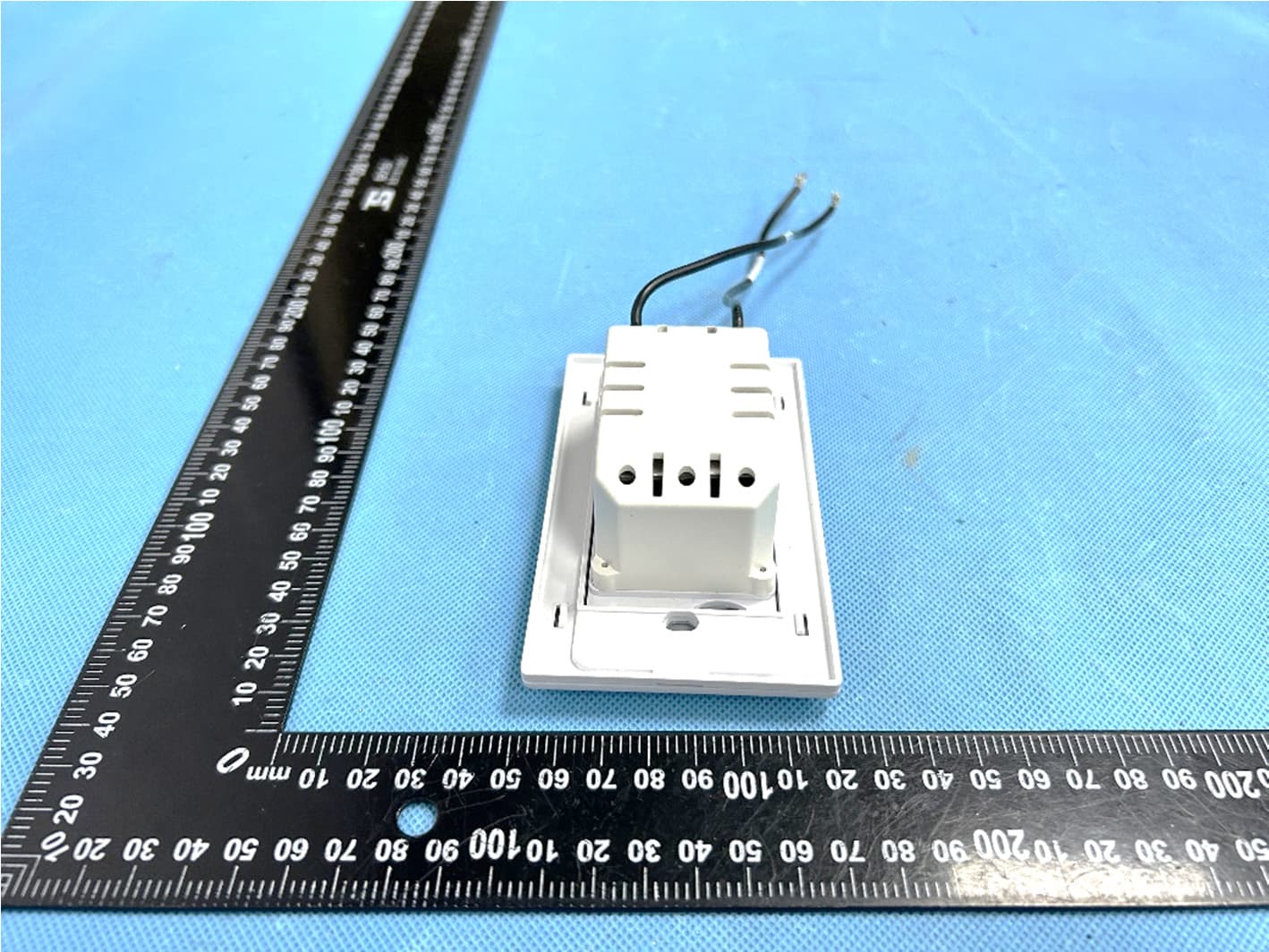
YNE-000170-12
Aug 12, 2024CEILING FAN WALL CONTROL
Equipment Class
DSC - Part 15 Security/Remote Control Transmitter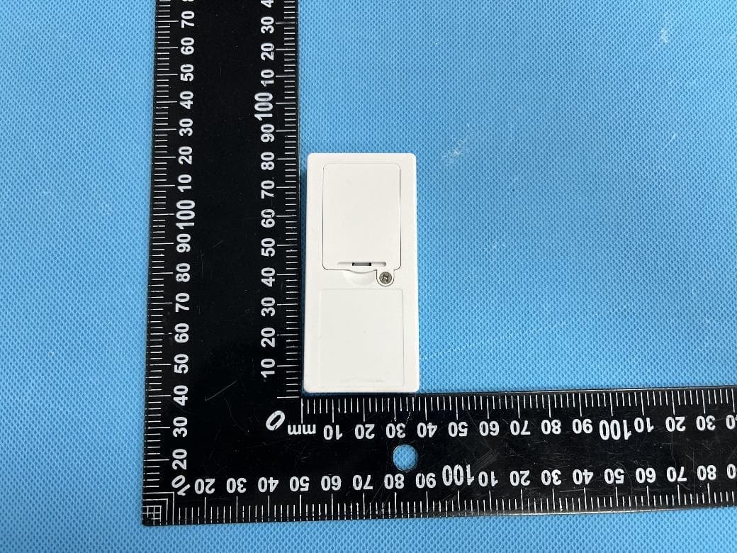
YNE-000170-04
Sep 20, 2023CEILING FAN REMOTE CONTROL
Equipment Class
DSC - Part 15 Security/Remote Control Transmitter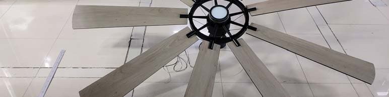
YNE-85GENTR
May 19, 2021Gentry XL LED 85in Fan
Equipment Class
CYY - Communications Receiver used w/Pt 15 Transmitter
YNE-65GENTR
May 18, 2021Gentry LED 65in Fan
Equipment Class
CYY - Communications Receiver used w/Pt 15 Transmitter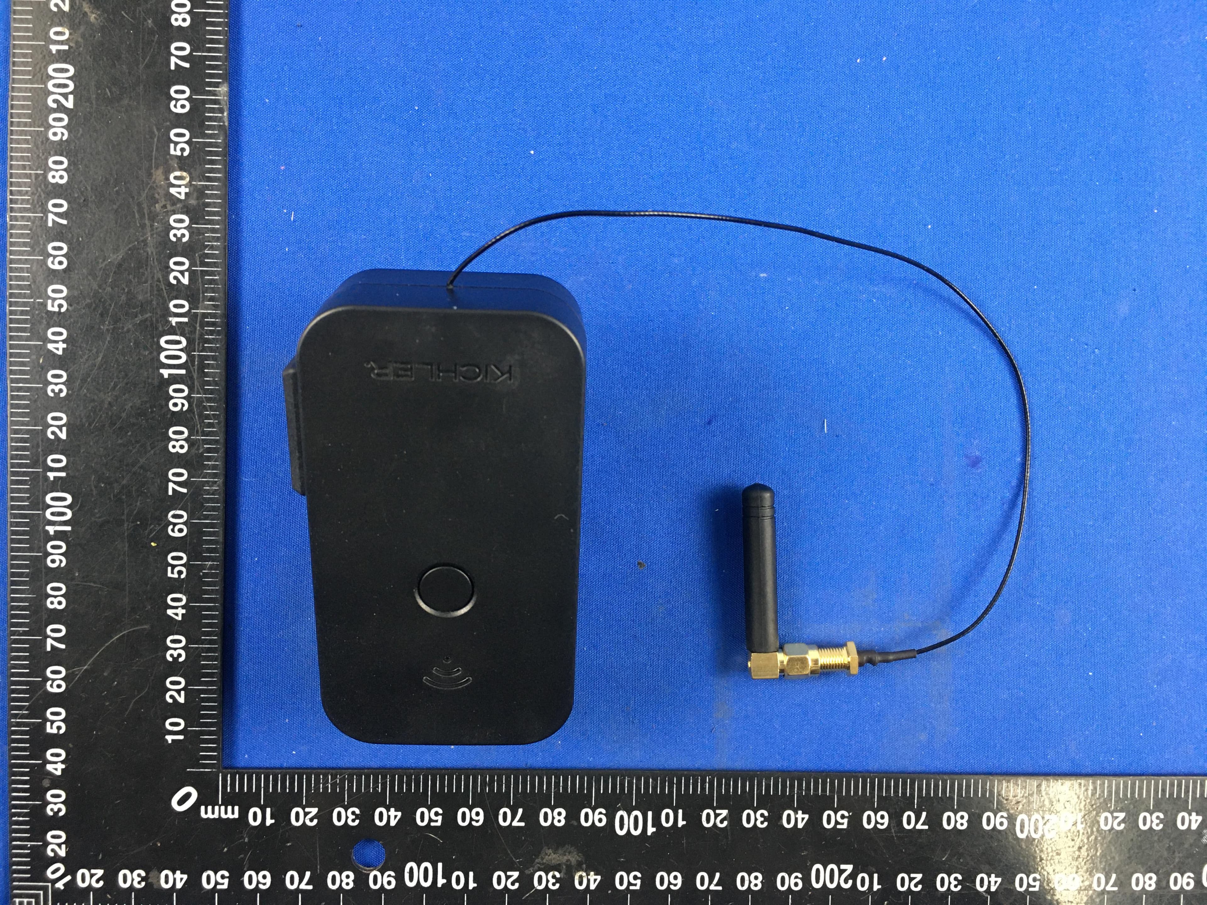
YNE16085BK
Feb 04, 2021SMART WIFI SOCKET
Equipment Class
DTS - Digital Transmission System