YNIJAZWARES15295Star Wars - Mouse
Jazwares, LLCApplication Details
- Equipment Class
- DXX - Part 15 Low Power Communication Device Transmitter
- Date of Grant
- Oct 25, 2011
- Application Purpose
- Original Equipment
- Date of Application
- Oct 25, 2011
- Equipment Note
- Star Wars - Mouse
- Frequency Range
- 2402.00000000 - 2480.00000000
- Company
- Jazwares, LLC
- Country
- United States
Documents & Files
Document Text
Text extracted from the exhibit documents filed with the FCC. Open a document above to read the original.
Users Manual
Congratulations on your purchase of the Wireless Mouse! We hope you enjoy all the great features of the clock. To get the most out of your Wireless Mouse please read this manual as it provides tips and information about its various features. Warning: Replacement of batteries must be done by an adult. Do not mix old and new batteries. Do not mix the alkaline, standard (carbon-zinc) and rechargeable (nickel-cadmium) batteries. The supply terminals are not to be short-circuited. Non-rechargeable batteries are not to be recharged. Exhausted batteries are to be removed. Only batteries of the equivalent type are to be used. Batteries are to be inserted with the correct polarity. Dispose of batteries properly. Do not dispose of batteries in fire ; batteries may explode or leak. Only use the adapter provided by the manufacturer. The mouse takes 2 X AAA Batteries. • Use this only as intended. • To prevent fire or shock hazard, do not expose this unit to rain or moisture. • Do not submerge the unit in any liquid • Do not disassemble SAFETY TIPS: Power Supply: Battery Information: Battery Compartment Nano Receiver On/Off Button • Nano receiver, plug-and-play • Wireless carrier frequency: 2402MHz-2480MHz • Perfect ergonomic design • Zero delay 2.4GHz & 16 channel transmitted at the same time, to provide a linear 10 meters effective operating distance. • Super 5 class intelligent power-saving mode, a battery can up to more than 6 months life • GFSK / DSSS FM automatic function, anti-interference ability is improved more than 8 times • 1000 dpi high precision, optical tracking engine • USB charging function, energy saving and environmental protection Technical Specifications: • Available USB Port • Windows ® XP, Vista or Higher • Macintosh OS 10.1 or Higher System Requirements: • Hold the mouse on both sides of the button, the battery cover can be opened automatically. • Put into two AAA alkaline batteries (enclosed in the package) • Insert the mini receiver into the computer spare USB interface, (suggested to insert on the front of the USB interface of computer, if need to use the back of computer USB interface, suggest to use the extended wire connection) • Turn the On/Off Switch to On. The mouse is all installed, please enjoy wireless fun! Installation Steps: USER GUIDE 2.4 GHz Wireless Mouse © Jazwares, Inc. 2011 2.4 GHz Wireless Mouse with Nano Receiver 2 AAA Batteries Instruction Manual PACKAGE CONTENTS * NOTE : After periods of inactivity, the mouse goes into sleep mode to conserve battery life. To wake the mouse simply move it in any direction and it should respond on the screen. If the mouse is not working, please follow the next steps. • Unplug receiver from computer terminal . Put the receiver into the distance of the mouse within 30 cm. While holding down the mouse left & right key and the wheel button 10 seconds. At the same time, let go, quickly insert receiver into the computer terminal. • Check the batteries, they may need to be replaced. • If you are still having problems, restart your PC and allow it to load up then check the mouse. Trouble Shooting: This equipment has been tested and found to comply with the limits for a Class B digital device, pursuant to Part 15 of the FCC rules. These limits are designed to provide reasonable protection against harmful interference in a residential installation. This equipment generates, uses and can radiate radio frequency energy and, if not installed and used in accordance with the instructions, may cause harmful interference to radio communications. However, there is no guarantee that interference will not occur in a particular installation. If this equipment does cause harmful interference to radio or television reception, which can be determined by switching the equipment off and on, the user is encouraged to try to correct the interference by one or more of the following measures: Reorient or relocate the receiving antenna. • Increase the separation between the equipment and receiver. • Connect the equipment into an outlet on a circuit different from that to which the receiver is connected. • Consult the dealer or an experience radio/TV technician for help. This equipment has been tested and found to comply with the limits for a Class B digital device, pursuant to Part 15 of the FCC rules. NOTES: FCC ID: YNIJAZWARES15295 FCC ID: YNIJAZWARES13595 WARRANTY COVERAGE Jazwares, Inc.’s warranty obligation is limited to the terms set forth below. WHO IS COVERED Jazwares, Inc. warrants the product to the original purchaser or the person receiving the product as a gift against defects in material & workmanship as based on the date of the original purchase from an authorized dealer or retailer. The original sales receipt showing the product name & the purchase date from an authorized retailer is considered such proof. Jazwares, Inc. warrants replacement products or parts provided under this warranty against defects in materials & workmanship from the date of the replacement or repair for ninety (90) days or for the remaining portion of the original product’s warranty, whichever provides longer coverage for you. When a product or part is exchanged, any replacement item becomes your property and the replaced item becomes Jazwares, Inc. property. Replacement product can only be sent if all warranty requirements are met. Failure to follow all requirements can result in delay. WHO IS COVERED Jazwares, Inc. warranty covers new products if a mechanical defect arises & a valid claim is received within the Ninety (90) Day Warranty Period. At its option, Jazwares, Inc. will either (1) repair the product at no charge,using new or refurbished replacement parts, or (2) exchange the product with a product that is new or which has been manufactured from new, or serviceable used parts & is at least functionally equivalent or most comparable to the original product in Jazwares, Inc.’s inventory. WHAT IS NOT COVERED - EXCLUSIONS & LIMITATIONS The limited warranty appl…
Text truncated - open the document above for the full version.
Block Diagram
Block Diagram FCC ID: YNIJAZWARES15295 3V 2AAA 2V7 DC/DC Regulator U5 MCU U3 RF Transceiver U2 Sensor U1 LED Key button Crystal Oscillator 4MHz Y1 Crystal Oscillator 12MHz Y2 EEPROM Reserved U4 Antenna Matching Circuit C28, C29 2402 ~ 2480MHz 2.4GHz RF Module Block Diagram
Operational Description
FCC ID: YNIJAZWARES15295 Technical Description : The brief circuit description is listed as follows : - U1 and associated circuit act as optical mouse sensor. - U2 and associated circuit act as 2.4GHz RF transceiver module. - U3 and associated circuit act as MCU. - U4 and associated circuit act as EEPROM. - Y2 and associated circuit act as Clock Oscillator of U2. - Y1 and associated circuit act as Clock Oscillator of U3. Antenna Used : A patch antenna has been used. SGN6210 RF Transceiver/Framer Production Data Sheet December 2006 SGN6210 Data Sheet Page 1 of 13 www.signiatech.com Product Description: The Signia SGN6210 IC is a low-cost, fully integrated CMOS radio frequency (RF) transceiver block, combined with a 64- byte buffered framer block. In normal applications, the SGN6210 is connected to a low-cost microcomputer (MCU). The on-chip framer processes and stores the RF data in the background, unloading this critical timing function from the MCU. This lowers MCU speed requirements, expedites product development time, and frees the MCU for implementing additional product features. The RF transceiver block is a self-contained, fast-hopping GFSK data modem, optimized for use in the widely available 2.4 GHz ISM band. It contains transmit, receive, VCO and PLL functions, including an on-chip channel filter and resonator, thus minimizing the need for external components. The receiver utilizes extensive digital processing for excellent overall performance, even in the presence of interference and transmitter impairments. Transmit power is digitally controlled. The low-IF receiver architecture results in sensitivity to -80 dBm or better, with impressive selectivity. The framer register settings determine the over-the-air formatting characteristics. Transmit data is easily sent over- the-air as a complete frame of data, with preamble, address, payload, and CRC. Receiving data is just the opposite, using the preamble to train the receiver clock recovery, then the address is checked, then the data is reverse formatted for receive, followed by CRC. All of this is done in hardware to ease the programming and overhead requirements of the baseband MCU. For longer battery life, power consumption is minimized by automatic enabling of the various transmit, receive, PLL, and PA sections, depending on the instantaneous state of the chip. A sleep mode is also provided for ultra low current consumption. This product is supplied in lead-free, RoHS compliant, 32-lead 5x5 mm JEDEC standard QFN package, featuring an exposed pad on the bottom for best RF characteristics. Key Features: • Combines 2.4 GHz GFSK RF transceiver with 8-bit data framer function • Eliminates need for external software or hardware FIFO; offloads MCU for other tasks • Simple microprocessor interface – 4 wires for SPI, plus 3 wires for RST/buffer control • Each transmit, receive buffer is 64 bytes deep • Long packets are possible if buffers are read/written before overflow/underflow occurs • Always 1 Mbps over-the-air symbol rate, regardless of MCU speed or architecture • Preamble can be 1 to 8 bytes • Supports 1, 2, 3, or 4 word address (up to 64 bits) • Various Payload data formats to eliminate DC offset, enhance receive clock recovery and BER • Programmable data whitening • Supports Forward Error Correction (FEC): none, 1/3, or 2/3 • Supports 16-bit CRC • Power management for minimizing current consumption • Lead-free 5x5mm QFN package with minimum RF parasitics Applications: • Wireless devices that need quick time-to-market • Battery Powered wireless devices • Wireless streaming audio • Home and factory automation • Simple and fast wireless data networks • Cordless headsets and Cellular Phones • Wireless voice and VOIP • Wireless security and access control Ordering Information SGN6210 RF Transceiver/Framer Signia Technologies, Inc. Phone: (408) 945-9988 500 Yosemite Dr., Suite 100 FAX: (408) 945-9119 Milpitas, CA 95035 USA [email protected] SGN6210 December 2006 SGN6210 Data Sheet Page 2 of 13 www.signiatech.com Block Diagram Ratings Absolute Maximum Ratings Rating Parameter Symbol MIN TYP MAX Unit Operating Temp. T OP -40 +85 o C Storage Temp. T STORAGE -55 +125 o C V DD_IO Supply Volt. V DDIO_MAX +3.7 V DD Supply Volt. V DD_MAX +2.5 VDC Applied Voltages to Other Pins V OTHER -0.3 +3.7 VDC Input RF Level P IN +10 dBm Output Load mismatch (Z 0 =50Ω) VSWR OUT 10:1 VSWR Notes: 1. Absolute Maximum Ratings indicate limits beyond which damage to the device may occur. Recommended operating conditions indicate conditions for which the device is intended to be functional, but do not guarantee specific performance limits. For guaranteed specifications and test conditions, see the Electrical Characteristics section below. 2. These devices are electro-static sensitive. Devices should be transported and stored in anti-static containers. Equipment and personnel contacting the devices need to be properly grounded. Cover workbenches with grounded conductive mats. SGN6210 December 2006 SGN6210 Data Sheet Page 3 of 13 www.signiatech.com Electrical Characteristics The following specifications are guaranteed for T A = 25 ° C, V DD = 1.80 ± 0.18 VDC, unless otherwise noted: Specification Parameter Symbol MIN TYP MAX UnitsTest Condition and Notes Current Consumption Current Consumption - TX I DD_TX 26 mA P OUT = nominal output power Current Consumption - RX I DD_RX 25 mA Current Consumption – DEEP IDLE I DD_D_IDLE 1.9 mA RF Synthesizer and VCO: OFF (see Reg. 21) Current Consumption - SLEEP I DD_SLP 3.5 uA Digital Inputs Logic input high V IH 0.8 V DD_io V DD_io V Logic input low V IL 0 0.8 V Input Capacitance C _IN 10 pF Input Leakage Current I _LEAK_IN 10 uA Digital Outputs Logic output high V OH 0.8 V DD_io V DD_io V Logic output low V OL 0.4 V Output Capacitance C _OUT 10 pF Output Leakage Current I _LEAK_OUT 10 uA Rise/Fall Time T _RISE_OUT 5 nS Clock Signals BRCLK output frequency F BRCLK 1, 12, or xtal Freq. MHz Depends on Register settings. Al…
Text truncated - open the document above for the full version.
Schematics
1 2 3 4 5 6 ABCD 6 5 4 3 2 1 D CBA COMPANY: COMPX( 展 展 展 展展 展 展 展展 展 展 展展 展 展 展 ) TITLE: REV: ver 3.0 NO: DATE: CX5183 SDO 1 LED 2 MOT 3 CS 4 SCK 5 VSS 6 VDD 7 SDI 8 U1ADNS5090 E4 10uF C7104 VCC LED2 LIGHT-LED SPI~MOSISPI~MISOSNS~SSSPI~CLKLED LED R15 100/* Mouse _ADNS5090 SNS~SS 1 23 ENC 编编编 ZAZB R0R1R2R3 LB RB MB FB CB DIPB BB C0 R5 100K VCC E2 47uF C6104 L1100uH D1 1N5819 E3100uF/16V VCC BT- BT+ 12 BAT BT+ 1 2 3 OUT VSS LX U5ME2100A-27P A0 1 A1 2 A2 3 A3 4 SDA 5 SCL 6 WP 7 VCC 8 U4 24LC01/02 R4 10K VCC EEP~DATEEP~CLK LED1FC/BL LED R111K/* VCC Sensor 方 方 方 方方 方 方 方方 方 方 方方 方 方 方 TCC 接 接接接 EEP~CLKTCC 接 接接接 EEP~DAT TCC 接 接接接 VCC RF~PKTRF~SSSPI~MISOSPI~CLKSPI~MOSI MOTZAZBEEP~CLKEEP~DATBLOWTCC VCC VCC OSCIOSCO Y1 4MHz C2 33PF C1 33PF C3 104 R171M C0R0 R1R2R3 R14 470K VCC R10 470K VCC CX5183-SSOP24 PA6 1 TCC 2 VCC 3 VSS 4 PA0 5 PA1 6 PA2 7 PA3 8 PB0 9 PB1 10 PB2 11 PB4 12 PB5 13 PB6 14 PB7 15 PC0 16 PC1 17 PC2 18 PC6 19 PC7 20 OSCO 21 OSCI 22 RESET 23 PA7 24 U3 MOT 2010/01/21 TCC 接 接 接 接 SPI~MOSI SPI~MOSI RF~PKT RF~SSSPI~CLKSPI~MISORF-PKT VDD ANTENNA +1.8V +1.8V +1.8V +1.8V XI 1 PLL_Vdd 2 VCO_Vdd 3 ANT 4 DBG 5 RF_Vdd 6 IF_Vdd 7 AMS_AVdd 8 BXTLEN 9 RXCLK 10 BPKTCTL 11 vss_dig 12 vdd_dig 13 BNDEN 14 BDATA 15 BDCLK 16 BNPWR 17 BDATA1 18 Vdd_io 19 Ldo_vout 20 CKPHA 21 Ams_DVss 22 AMS_DVdd 23 XO 24 Die 25 U2 SGN6210-QFN24 +1.8V Y2 12MHz(+/-10ppm)/20pF C29 5.6nH C28 0R C30* C24 0.1UF C250.01UF C22 0.1UF C23 2.2UF C270.1UF C260.1UF C2133PF C2033PF R21 680K R20 2.2K SW1 E4 10uF R610R
Test Report
INTERTEK TESTING SERVICES Report No.: HK11090844-1 Sample No.: 1/3 (Mouse -Star Wars) Code: FCC15C_f / Effective Date: 24 Jun 2011 ( of ) Average factor Plot – Pursuant to FCC Part 15 Section 15. 249 Requirement INTERTEK TESTING SERVICES Report No.: HK11090844-1 Sample No.: 1/3 (Mouse -Star Wars) Code: FCC15C_f / Effective Date: 24 Jun 2011 ( of ) Average factor Plot – Pursuant to FCC Part 15 Section 15. 249 Requirement
Test Report
INTERTEK TESTING SERVICES Report No.: HK11090844-1 Sample No.: 1/3 (Mouse -Star War) Code: FCC15C_f / Effective Date: 24 Jun 2011 ( of ) Bandedge Plot – Pursuant to FCC Part 15 Section 15. 249 Requirement
Test Report
- The test report only allows to be revised within the retention period unless further standard or the requirement was noticed. - This report is for the exclusive use of Intertek's Client and is provided pursuant to the agreement between Intertek and its Client. Intertek's responsibility and liability are limited to the terms and conditions of the agreement. Intertek assumes no liability to any party, other than to the Client in accordance with the agreement, for any loss, expense or damage occasioned by the use of this report. Only the Client is authorized to permit copying or distribution of this report and then only in its entirety. Any use of the Intertek name or one of its marks for the sale or advertisement of the tested material, product or service must first be approved in writing by Intertek. The observations and test results in this report are relevant only to the sample tested. This report by itself does not imply that the material, product, or service is or has ever been under an Intertek certification program. Intertek Testing Services Hong Kong Ltd. 2/F., Garment Centre, 576 Castle Peak Road, Kowloon, Hong Kong. Tel: (852) 2173 8888 Fax: (852) 2785 5487 Website: www.hk.intertek-etlsemko.com TEST REPORT Report No.: HK11090844-1 Jazwares Inc Application For Certification (Original Grant) (FCC ID: YNIJAZWARES15295) Transceiver Prepared and Checked by: Approved by: Signed On File Wong Kwok Yeung, Kenneth Lead Engineer Chan Chi Hung, Terry Assistant Supervisor Date: October 24, 2011 INTERTEK TESTING SERVICES Report No.: HK11090844-1 FCC ID: YNIJAZWARES15295 i GENERAL INFORMATION Jazwares Inc BRAND NAME: Star Wars, MODEL: 15295 FCC ID: YNIJAZWARES15295 Grantee: Jazwares Inc Grantee Address: 1067 Shotgun Road, Sunrise, FL 33326, USA. Contact Person: Vincent Yang Tel: 954.845.0800 Fax: 954.472.8190 e-mail: [email protected] Manufacturer: N/A Manufacturer Address: N/A Brand Name: Star Wars Model: 15295 Type of EUT: Transceiver Description of EUT: Star Wars - Mouse Serial Number: N/A FCC ID: YNIJAZWARES15295 Date of Sample Submitted: September 22, 2011 Date of Test: October 06, 2011 Report No.: HK11090844-1 Report Date: October 24, 2011 Environmental Conditions: Temperature: +10 to 40°C Humidity: 10 to 90% INTERTEK TESTING SERVICES Report No.: HK11090844-1 FCC ID: YNIJAZWARES15295 ii SUMMARY OF TEST RESULT Jazwares Inc BRAND NAME: Star Wars, MODEL: 15295 FCC ID: YNIJAZWARES15295 TEST SPECIFICATION REFERENCE RESULTS Maximum Peak Output Power 15.247(b), (c) / RSS-210 A8.4 N/A Hopping Channel Carrier Frequencies Separation 15.247(e) / RSS-210 A8.1 N/A 20dB Bandwidth of the Hopping Channel 15.247(a) / RSS-210 A8.1 N/A Number of Hopping Frequencies 15.247(e) / RSS-210 A8.1 N/A Average Time of Occupancy of Hopping Frequency 15.247(e) / RSS-210 A8.1 N/A Antenna Conducted Spurious Emissions 15.247(d) / RSS-210 A8.5 N/A Radiated Spurious Emissions 15.247(d) / RSS-210 A8.5 N/A RF Exposure Compliance 15.247(i) / RSS-Gen 5.6 N/A Transmitter Power Line Conducted Emissions 15.207 / RSS-Gen 7.2.4 N/A Transmitter Field Strength 15.227 / RSS-310 3.8 N/A Transmitter Field Strength 15.229 / RSS-210 A2.7 N/A Transmitter Field Strength, Bandwidth and Timing Requirement 15.231(a) / RSS-210 A1.1.1 N/A Transmitter Field Strength, Bandwidth and Timing Requirement 15.231(e) / RSS-210 A1.1.5 N/A Transmitter Field Strength and Bandwidth Requirement 15.239 / RSS-210 A2.8 N/A Transmitter Field Strength and Bandwidth Requirement 15.249 / RSS-210 A2.9 Pass Transmitter Field Strength and Bandwidth Requirement 15.235 / RSS-310 3.9 N/A Digital Device Radiated Emissions 15.109 / RSS-210 2.5 Pass Digital Device Conducted Emissions 15.107 / ICES-003 N/A Note: 1. The EUT uses a permanently attached antenna which, in accordance to section 15.203, is considered sufficient to comply with the pervisions of this section. 2. Pursuant to FCC part 15 Section 15.215(c), the 20 dB bandwidth of the emission was contained within the frequency band designated (mentioned as above) which the EUT operated. The effects, if any, from frequency sweeping, frequency hopping, other modulation techniques and frequency stability over excepted variations in temperature and supply voltage were considered. INTERTEK TESTING SERVICES Report No.: HK11090844-1 FCC ID: YNIJAZWARES15295 iii Table of Contents 1.0 General Description....................................................................................... 1 1.1 Product Description ...................................................................................... 1 1.2 Related Submittal(s) Grants .......................................................................... 1 1.3 Test Methodology ......................................................................................... 1 1.4 Test Facility .................................................................................................. 1 2.0 System Test Configuration ............................................................................ 2 2.1 Justification................................................................................................... 2 2.2 EUT Exercising Software .............................................................................. 2 2.3 Special Accessories...................................................................................... 2 2.4 Equipment Modification................................................................................. 2 2.5 Measurement Uncertainty ............................................................................. 2 2.6 Support Equipment List and Description........................................................ 2 3.0 Emission Results ........................................................................................... 3 3.1 Field Strength Calculation ............................................................................. 3 3.2 Radiated Emission Configuration Photograph ............................................... 4 3.3 Radiated Emis…
Text truncated - open the document above for the full version.
Test Setup Photos
INTERTEK TESTING SERVICE Report No: HK11090844-1 FCC ID: YNIJAZWARES15295 Configuration Photographs Worst-Case Radiated Emissions (Front View) Model : 15295 Radiated Emission Model: 15295 Job: HK11090844-1 A5B INTERTEK TESTING SERVICE Report No: HK11090844-1 FCC ID: YNIJAZWARES15295 Configuration Photographs Worst-Case Radiated Emissions (Back View) Model : 15295 Radiated Emission Model: 15295 Job: HK11090844-1 A B5
Contact Information
Applicant
Simon Ng(Director of Compliance & Quality Assurance)
Technical Contact
Intertek Testing Services Hong Kong Ltd.Terry Chan
[email protected](852) 2173 8503
2/F., Garment Centre, · Kowloon · Hong Kong
Non-Technical Contact
Intertek Testing Services Hong Kong Ltd.Terry Chan
[email protected](852) 2173 8503
Test Firm
Intertek Testing Services Hong Kong Ltd.Billy Chow
Technical Specifications
| # | Rule Parts | Frequency Range | Power Output |
|---|---|---|---|
| 1 | 15C | 2.40 GHz - 2.48 GHz | - |
Other Applications from Jazwares, LLC
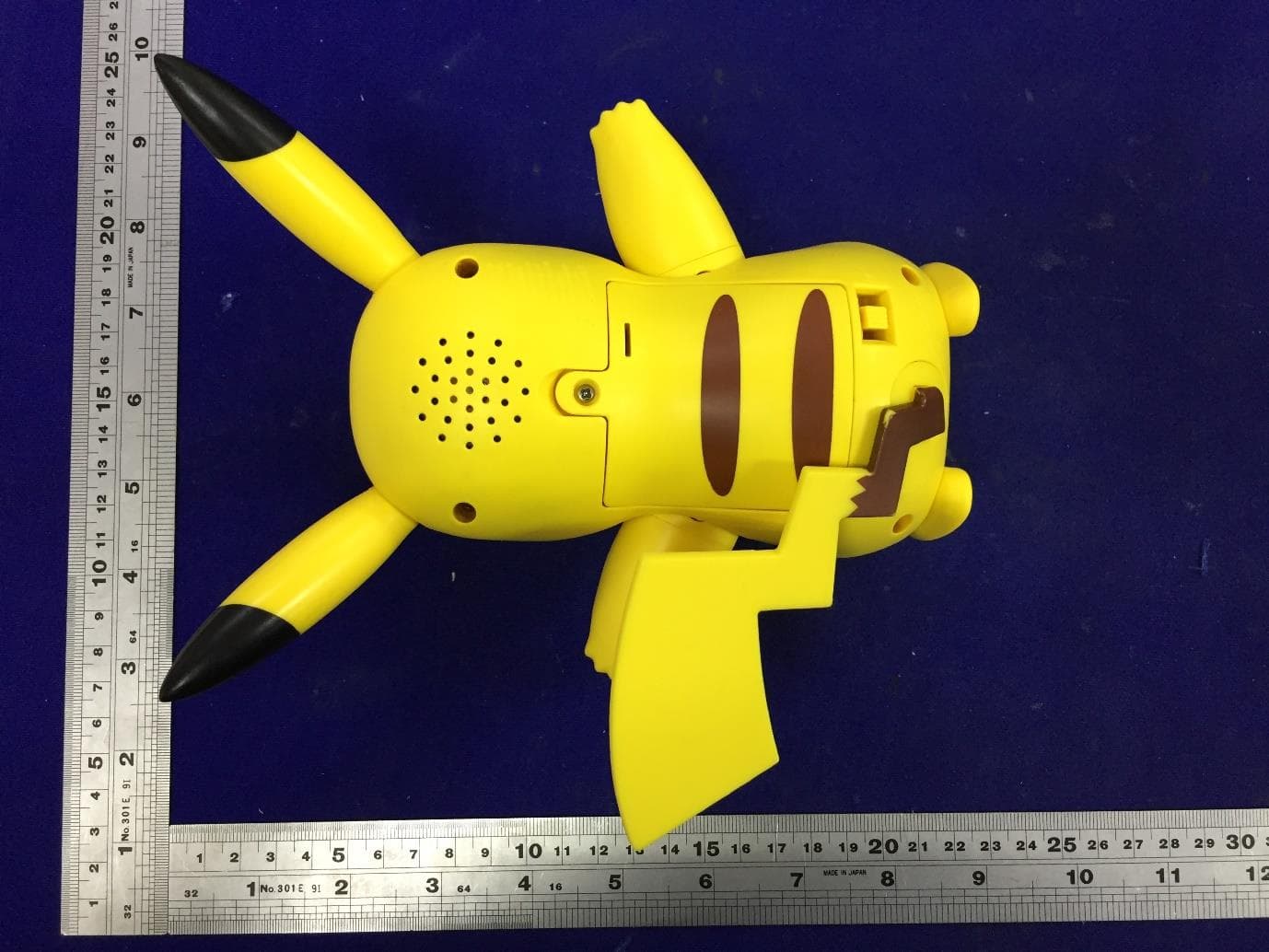
YNIJAWSPKW3330
Apr 16, 2023PKW3330-PKW - Deluxe Feature Figure (TBD Pikachu)
Equipment Class
DXX - Part 15 Low Power Communication Device Transmitter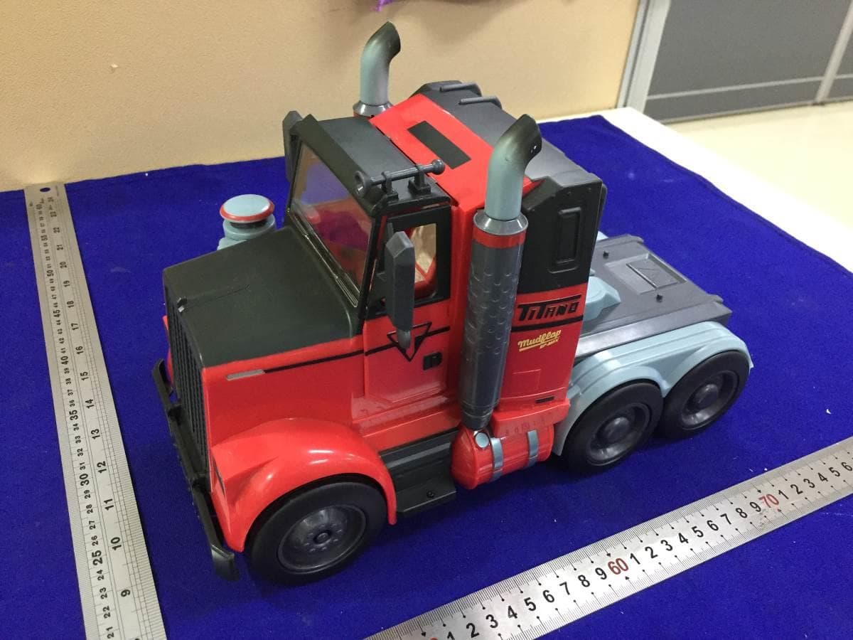
YNIJAZWARES733
Jun 27, 2021FNT0733 - FNT - Deluxe Feature Vehicle (RC Mudflap)
Equipment Class
DXX - Part 15 Low Power Communication Device Transmitter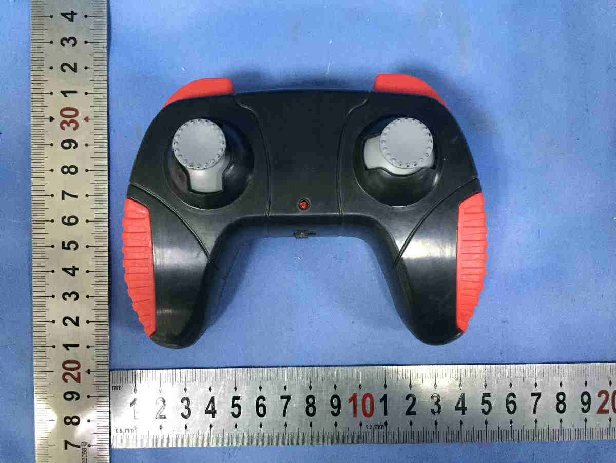
YNIJAZWARES73A
Jun 27, 2021FNT0733 - FNT - Deluxe Feature Vehicle (RC Mudflap)
Equipment Class
DXX - Part 15 Low Power Communication Device Transmitter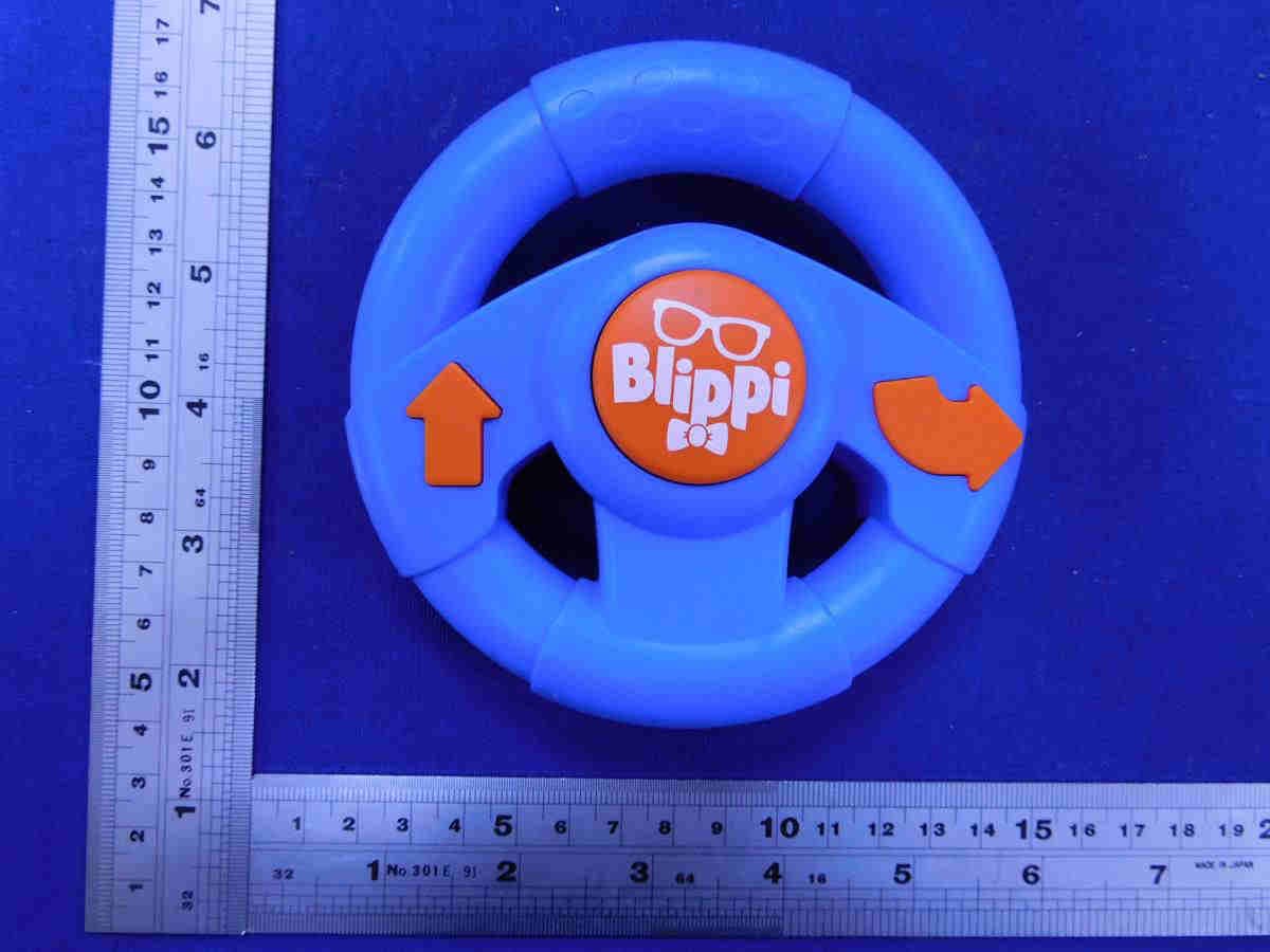
YNIJAZWARES138
May 19, 2021TBLP0139-BLP-Remote Control Vehicle (RC Racecar)
Equipment Class
DXX - Part 15 Low Power Communication Device Transmitter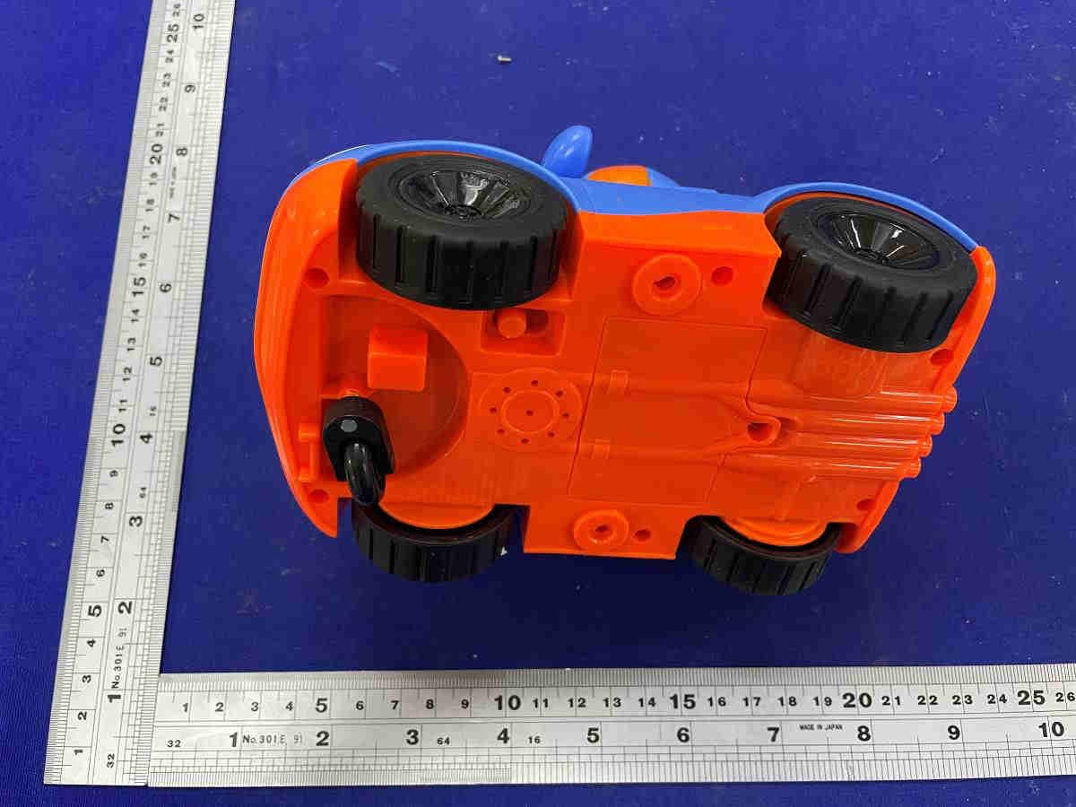
YNIJAZWARES139
May 19, 2021TBLP0139-BLP-Remote Control Vehicle (RC Racecar)
Equipment Class
DXX - Part 15 Low Power Communication Device Transmitter