YOPGS1011MIPLow Power Wi-Fi Module
Gainspan Corporation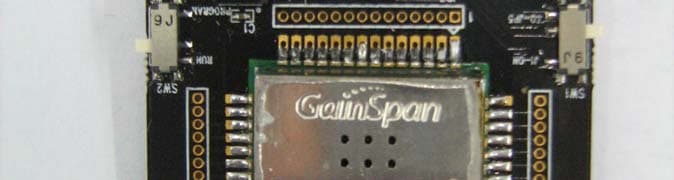
Click to zoom
Application Details
- Equipment Class
- DTS - Digital Transmission System
- Date of Grant
- Oct 04, 2010
- Application Purpose
- Original Equipment
- Date of Application
- Oct 04, 2010
- Equipment Note
- Low Power Wi-Fi Module
- Frequency Range
- 2412.00000000 - 2462.00000000
- Company
- Gainspan Corporation
- Country
- United States
Documents & Files
Document Text
Text extracted from the exhibit documents filed with the FCC. Open a document above to read the original.
Users Manual
User Manual: Serial to Wi-Fi Evaluation Kit PRELIMINARY PAGE 1 OF 12 CONFIDENTIAL INTRODUCTION HE GAINSPAN GS1011MXX EVALUATION KIT offers a quick and easy way to evaluate the GainSpan GS1011M ultra-low-power wireless module and embedded platform software for Wi-Fi ® networks based on the GS1011 SOC ultra-low-power Wi-Fi System-On-Chip. The default firmware pre-loaded on the Evaluation kit is the serial to Wi-Fi application. The GS1011M can be used as transparent bridge to carry serial (UART) traffic over an 802.11 wireless link. The quick start guide provides the steps required to construct the serial to Wi-Fi bridge. GAINSPAN EVALUATION KIT COMPONENTS The GS-SOC Evaluation Kit includes the following items: ► GS1011M based Evaluation Board (GS1011MxP-EVB or GS1011MEE-DB) ► Power Source (Battery or 3.3V DC adapter) ► Serial Cable (USB to UART or DB9) ► Standard Wi-Fi ® Wireless Access Point. ► GainSpan USB Flash Drive,which includes: Product Documentation including Evalkit_Setup.exe Java Environment Installer SW Utilities (Wireshark, TeraTerm and Sim Term terminal software) ► This Manual Copyright © 2009 by GainSpan Corporation. All rights reserved. GainSpan and GainSpan logo are trademarks or registered trademarks of GainSpan Corporation. Other trademarks are the property of their owners.Specifications, features, and availability are subject to change without notice. T Serial to Wi-Fi Start Up Guide PRELIMINARY PAGE 2 OF 12 CONFIDENTIAL EVALUATION BOARD DETAILS This section describes the various interfaces and jumper settings for the GS1011MxP-EVB board. 6-pin UART Connector GS1011MxP Module Temperature SensorLight Sensor Alarm Switch On/Off Switch Power Supply Header WPS Switch RS232 DB9 Connector Serial Select Jumper Program Switch LEDs Power Source Select Battery Holder Power Mode 6-pin UART Connector GS1011MxP Module Temperature SensorLight Sensor Alarm Switch On/Off Switch Power Supply Header WPS Switch RS232 DB9 Connector Serial Select Jumper Program Switch LEDs Power Source Select Battery Holder Power Mode Feature Description RF Module GS1011MIP – Internal PA and PCB antenna or GS1011MEP – External PA and PCB antenna RF Output Power (Typical) 9 dBm with GS1011MIP 18 dBm with GS1011MEP Antenna Type On-board PCB Trace (GS1011MxP) I/O Port (J1 or J2) J1: 6-pin serial UART ( 3.3V TTL) or J2: RS232 DB9 Connector LED 2 LED’s to indicate state WPS Switch (SW2) Push button for Wi-Fi Protected Setup Alarm Switch (SW4) Push button for Alarm and configuration Program Switch (SW3) RUN: Normal Operation (default) PROGRAM: For programming the GS1011M module: On/Off Switch (SW1) Power on/off switch Serial Select Jumper ( J4) 1-2 : RS232 Interface (DB9) 2-3: 6-pin UART (default) Sensors Temperature and Light Power Source Select (J9) 1-2: Ext Lab DC power supply 2-3: Battery (default) Battery Two 1.5V AA Battery (Alkaline or Lithium) Lithium is recommended for longer battery life Power Mode (J8) 1-2: Always On (Power is always on) 2-3: Standby Mode (Power is turned off to the board during standby state) - default Power Measurement Jumper (J8) Jumper to facilitate measurement of current consumption for module Power Supply Header Jumper posts for connecting Lab DC power supply Power Source Range 2.7V to 3.6V Serial to Wi-Fi Start Up Guide PRELIMINARY PAGE 3 OF 12 CONFIDENTIAL INSTALLATION STEPS FOR EVALUATION KIT SOFTWARE The USB key in the evaluation kit contains multiple SW components that can be installed for evaluating the various applications on the evaluation board. System Requirements: PC with Windows XP Service Pack 2 or Windows Vista. with at least one Ethernet port, and a PC with a serial or USB port. (A single PC can provide both the serial and Ethernet connections, if desired.) Install Java Runtime Environment If you have Java Runtime Environment (JRE) Version 6 Update 14 or later, you should be able to run the GSDemo GUI application that are installed as part of the Eval kit installation. If not, you can download the current version of JRE from http://www.java.com/en/download/manual.jsp or run jre-6uXY-windows-i586-p-s.exe from the USB flash drive received with your Evaluation Kit, where XY may vary depending on the update provided. Install Serial Terminal Software Install the Tera Term serial terminal software (teraterm_utf8-4.58.exe). If you already have tera term or use a different terminal software, then you can skip this step. Evaluation Kit Software Installation Installs the Serial to Wi-Fi application binaries, GSDemo GUI for the temperature and light sen- sor application and drivers required for serial configuration. Run evalkit_setup.exe from the USB flash drive. This starts the InstallShield Wizard. Perform a “Typical” installation, using all default settings. This creates and populates the C:\GainSpan\EvalKit\X.X.X directory. Note: Directory names and organization may differ slightly from one release to another; If you have already installed earlier versions of GainSpan software, the most recent release will be add- ed in a separate folder. Copy Sim_terminal.exe from the USB key to the EvalKit directory created in this step. The sim terminal is a serial terminal with --- TCP/UDP client available from GainSpan. Note that Simple Terminal requires the .NET framework, 2.0 or above; You can download that .net framework from http://www.microsoft.com/downloads/en/default.aspx USB/UART Cable Driver Installation Note: If using RS232 (DB9) cable, then this step can be skipped If USB to UART cable provided with the kit is used, then install the driver for this cable from C:\GainSpan\S2wEvalKit\1_1_2\drivers\usb_uart directory that was created previous step. The file is labeled CDM 2.02.04. Serial to Wi-Fi Start Up Guide PRELIMINARY PAGE 4 OF 12 CONFIDENTIAL SERIAL TO WI-FI SETUP AND START UP INSTRUCTIONS Below are the steps required to run the serial to Wi-Fi application. 1. Once the software installation is completed, power the Wi-Fi Access Point (AP). The access point have be…
Text truncated - open the document above for the full version.
External Photos
TUV Rheinland Product Under Test Photo 1279 Quarry Lane, Ste. A, Pleasanton, CA 95466 Tel: (925) 249-9123, Fax: (925) 249-9124 Report Number: 31051809.001 Page 1 of 2 EUT: WiFi Module Model: GS1011MIP EMC / Rev 9/30/2010 FCCID: YOPGS1011MIP, IC ID: 9154AGS1011MIP 1.1 Product Under Test Photo Figure 1: External Photo of GS1011MIP WiFi Module on the Support Card (Component Side) TUV Rheinland Product Under Test Photo 1279 Quarry Lane, Ste. A, Pleasanton, CA 95466 Tel: (925) 249-9123, Fax: (925) 249-9124 Report Number: 31051809.001 Page 2 of 2 EUT: WiFi Module Model: GS1011MIP EMC / Rev 9/30/2010 FCCID: YOPGS1011MIP, IC ID: 9154AGS1011MIP Figure 2: External Photo of GS1011MIE WiFi Module on the Support Card (Soldered Side)
ID Label/Location Info
GainSpan Wi-Fi Module Product Label Specifications: Sample Label: GS1011MIP 1.2FCC ID: YOPGS1011MIPYYWW NNNN TWMAC: 001DC9XXXXXX Barcode of MAC Address Line #3: Date Code, Lot number, and Manufacturing Location Line #4: MAC Address = Serial Number Line #2: FCC ID 0.800"" 0.600"" Line #1: GainSpan Part Number and Revision number Product Label shall be applied on top of the RF Shield below the venting holes. GS1011MIP 1.2FCC ID: YOPGS1011MIPYYWW NNNN TWMAC: 001DC9XXXXXX
Test Report
The test results contained in this report refer exclusively to the product(s) presented for testing. No liability may be assumed for models or products not referred to herein. This test report may not be published or duplicated in part without permission of the testing body. This test report by itself does not constitute authorization for the use of any TUV Rheinland test mark. This report must not be used by the applicant to claim product certification, approval, or endorsement by NVLAP, NIST, or any agency of the federal government. Report Number: 31051809.001 Page 1 of 87 EUT: Wi-Fi Module Model: GS1011MIP EMC / Rev 9/9/2010 FCCID: YOPGS1011MIP, IC ID: 9154AGS1011MIP Emissions Test Report EUT Name: Wi-Fi Module Model No.: GS1011MIP CFR 47 Part 15.247 2010 and RSS 210: 2007 Prepared for: Ron Green Gainspan Corporation 125 S. Market St. Suite 400 San Jose, CA 95113-2292 Tel: (408) 673-2900 Fax: (408) 673-2901 Prepared by: TUV Rheinland of North America, Inc. 1279 Quarry Lane Pleasanton, CA 94566 Tel: (925) 249-9123 Fax: (925) 249-9124 http://www.tuv.com/ Report/Issue Date: 12 July 2010 Report Number: 31051809.001 Statement of Compliance The test results contained in this report refer exclusively to the product(s) presented for testing. No liability may be assumed for models or products not referred to herein. This test report may not be published or duplicated in part without permission of the testing body. This test report by itself does not constitute authorization for the use of any TUV Rheinland test mark. This report must not be used by the applicant to claim product certification, approval, or endorsement by NVLAP, NIST, or any agency of the federal government. Report Number: 31051809.001 Page 2 of 87 EUT: Wi-Fi Module Model: GS1011MIP EMC / Rev 9/9/2010 FCCID: YOPGS1011MIP, IC ID: 9154AGS1011MIP Manufacturer: Gainspan Corporation 125 S. Market St. Suite 400 San Jose, CA 95113-2292 (408) 673-2900 Requester / Applicant: Ron Green Name of Equipment: Wi-Fi Module Model No. GS1011MIP Type of Equipment: Intentional Radiator Application of Regulations: CFR 47 Part 15.247 2010 and RSS 210: 2007 Test Dates: July 1 to July 8, 2010 Guidance Documents: Emissions: ANSI C63.10: 2009 Test Methods: Emissions: ANSI C63.10: 2009 The electromagnetic compatibility test and documented data described in this report has been performed and recorded by TUV Rheinland, in accordance with the standards and procedures listed herein. As the responsible authorized agent of the EMC laboratory, I hereby declare that the equipment described above has been shown to be compliant with the EMC requirements of the stated regulations and standards based on these results. If any special accessories and/or modifications were required for compliance, they are listed in the Executive Summary of this report. This report must not be used to claim product endorsement by NVLAP or any agency of the U.S. Government. This report contains data that are not covered by NVLAP accreditation. This report shall not be reproduced except in full, without the written authorization of TUV Rheinland of North America. Jeremy Luong Conan Boyle Test Engineer Date NVLAP Signatory Date US5254 2932M-1 Table of Contents The test results contained in this report refer exclusively to the product(s) presented for testing. No liability may be assumed for models or products not referred to herein. This test report may not be published or duplicated in part without permission of the testing body. This test report by itself does not constitute authorization for the use of any TUV Rheinland test mark. This report must not be used by the applicant to claim product certification, approval, or endorsement by NVLAP, NIST, or any agency of the federal government. Report Number: 31051809.001 Page 3 of 87 EUT: Wi-Fi Module Model: GS1011MIP EMC / Rev 9/9/2010 FCCID: YOPGS1011MIP, IC ID: 9154AGS1011MIP 1 Executive Summary _______________________________________________________ 8 1.1 Scope______________________________________________________________________ 8 1.2 Purpose____________________________________________________________________ 8 1.3 Summary of Test Results _____________________________________________________ 8 1.4 Special Accessories __________________________________________________________ 8 1.5 Equipment Modifications _____________________________________________________ 8 2 Laboratory Information ____________________________________________________ 9 2.1 Accreditations & Endorsements _______________________________________________ 9 2.1.1 US Federal Communications Commission _______________________________________________ 9 2.1.2 NIST / NVLAP ____________________________________________________________________ 9 2.1.3 Canada – Industry Canada ___________________________________________________________ 9 2.1.4 Japan – VCCI _____________________________________________________________________ 9 2.1.5 Acceptance by Mutual Recognition Arrangement _________________________________________ 9 2.2 Test Facilities ______________________________________________________________ 10 2.2.1 Emission Test Facility _____________________________________________________________ 10 2.2.2 Immunity Test Facility _____________________________________________________________ 10 2.3 Measurement Uncertainty ___________________________________________________ 11 2.3.1 Sample Calculation – radiated & conducted emissions ____________________________________ 11 2.3.2 Measurement Uncertainty Emissions __________________________________________________ 12 2.4 Calibration Traceability _____________________________________________________ 12 3 Product Information ______________________________________________________ 13 3.1 Product Description ________________________________________________________ 13 3.2 Equipment Configuration ___________________________________________________ 13 3.3 Operating Mode ___________________________________________________________ 13 3.4 Unique Antenna…
Text truncated - open the document above for the full version.
Test Setup Photos
TUV Rheinland Test Setup Photo 1279 Quarry Lane, Ste. A, Pleasanton, CA 95466 Tel: (925) 249-9123, Fax: (925) 249-9124 Report Number: 31051809.001 Page 1 of 12 EUT: WiFi Module Model: GS1011MIP EMC / Rev 9/30/2010 FCCID: YOPGS1011MIP, IC ID: 9154AGS1011MIP 1 Photo 1.1 Test Setup Photo Figure 1: 30 MHz to 1000 MHz Radiated Emission Setup (Front View) TUV Rheinland Test Setup Photo 1279 Quarry Lane, Ste. A, Pleasanton, CA 95466 Tel: (925) 249-9123, Fax: (925) 249-9124 Report Number: 31051809.001 Page 2 of 12 EUT: WiFi Module Model: GS1011MIP EMC / Rev 9/30/2010 FCCID: YOPGS1011MIP, IC ID: 9154AGS1011MIP Figure 2: 30 MHz to 1000 MHz Radiated Emission Setup (Rear View) TUV Rheinland Test Setup Photo 1279 Quarry Lane, Ste. A, Pleasanton, CA 95466 Tel: (925) 249-9123, Fax: (925) 249-9124 Report Number: 31051809.001 Page 3 of 12 EUT: WiFi Module Model: GS1011MIP EMC / Rev 9/30/2010 FCCID: YOPGS1011MIP, IC ID: 9154AGS1011MIP Figure 3: Test Setup for 1GHz to 18GHz (Front View) TUV Rheinland Test Setup Photo 1279 Quarry Lane, Ste. A, Pleasanton, CA 95466 Tel: (925) 249-9123, Fax: (925) 249-9124 Report Number: 31051809.001 Page 4 of 12 EUT: WiFi Module Model: GS1011MIP EMC / Rev 9/30/2010 FCCID: YOPGS1011MIP, IC ID: 9154AGS1011MIP Figure 4: Test Setup for 1GHz to 18GHz (Rear View) TUV Rheinland Test Setup Photo 1279 Quarry Lane, Ste. A, Pleasanton, CA 95466 Tel: (925) 249-9123, Fax: (925) 249-9124 Report Number: 31051809.001 Page 5 of 12 EUT: WiFi Module Model: GS1011MIP EMC / Rev 9/30/2010 FCCID: YOPGS1011MIP, IC ID: 9154AGS1011MIP Figure 5: Test Setup for 18 GHz to 26GHz (Front View) TUV Rheinland Test Setup Photo 1279 Quarry Lane, Ste. A, Pleasanton, CA 95466 Tel: (925) 249-9123, Fax: (925) 249-9124 Report Number: 31051809.001 Page 6 of 12 EUT: WiFi Module Model: GS1011MIP EMC / Rev 9/30/2010 FCCID: YOPGS1011MIP, IC ID: 9154AGS1011MIP Figure 6: Test Setup for 18 GHz to 26GHz (Rear View) TUV Rheinland Test Setup Photo 1279 Quarry Lane, Ste. A, Pleasanton, CA 95466 Tel: (925) 249-9123, Fax: (925) 249-9124 Report Number: 31051809.001 Page 7 of 12 EUT: WiFi Module Model: GS1011MIP EMC / Rev 9/30/2010 FCCID: YOPGS1011MIP, IC ID: 9154AGS1011MIP Figure 7: Radiated Emission Setup on X-Axis TUV Rheinland Test Setup Photo 1279 Quarry Lane, Ste. A, Pleasanton, CA 95466 Tel: (925) 249-9123, Fax: (925) 249-9124 Report Number: 31051809.001 Page 8 of 12 EUT: WiFi Module Model: GS1011MIP EMC / Rev 9/30/2010 FCCID: YOPGS1011MIP, IC ID: 9154AGS1011MIP Figure 8: Radiated Emission Setup on Y-Axis TUV Rheinland Test Setup Photo 1279 Quarry Lane, Ste. A, Pleasanton, CA 95466 Tel: (925) 249-9123, Fax: (925) 249-9124 Report Number: 31051809.001 Page 9 of 12 EUT: WiFi Module Model: GS1011MIP EMC / Rev 9/30/2010 FCCID: YOPGS1011MIP, IC ID: 9154AGS1011MIP Figure 9: Radiated Emission Setup on Z-Axis TUV Rheinland Test Setup Photo 1279 Quarry Lane, Ste. A, Pleasanton, CA 95466 Tel: (925) 249-9123, Fax: (925) 249-9124 Report Number: 31051809.001 Page 10 of 12 EUT: WiFi Module Model: GS1011MIP EMC / Rev 9/30/2010 FCCID: YOPGS1011MIP, IC ID: 9154AGS1011MIP Figure 10: AC Conducted Emission (Front View) TUV Rheinland Test Setup Photo 1279 Quarry Lane, Ste. A, Pleasanton, CA 95466 Tel: (925) 249-9123, Fax: (925) 249-9124 Report Number: 31051809.001 Page 11 of 12 EUT: WiFi Module Model: GS1011MIP EMC / Rev 9/30/2010 FCCID: YOPGS1011MIP, IC ID: 9154AGS1011MIP Figure 11: AC Conducted Emission (Side View) TUV Rheinland Test Setup Photo 1279 Quarry Lane, Ste. A, Pleasanton, CA 95466 Tel: (925) 249-9123, Fax: (925) 249-9124 Report Number: 31051809.001 Page 12 of 12 EUT: WiFi Module Model: GS1011MIP EMC / Rev 9/30/2010 FCCID: YOPGS1011MIP, IC ID: 9154AGS1011MIP Figure 12: Conducted Test at RF Output Port for WiFi Module
Contact Information
Applicant
Paolomaria Schiratti(VP Global Certification)
Technical Contact
Gainspan CorporationRon Green
[email protected]408-673-2819
125 South Market St. · San Jose, California · United States
Non-Technical Contact
Gainspan CorporationRon Green
[email protected]408-673-2819
Test Firm
TUV Rheinland of North America Inc.Kent Chesley
Technical Specifications
| # | Rule Parts | Frequency Range | Power Output | Emission | Tolerance |
|---|---|---|---|---|---|
| 1 | 15C | 2.41 GHz - 2.46 GHz | 80.00 mW | G1D | 25.0000000000 ppm |
Other Applications from Gainspan Corporation
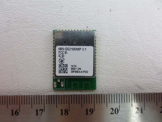
YOPGS2100MIP
Jun 24, 2014Ultra-Low Power Wi-Fi Module
Equipment Class
DTS - Digital Transmission System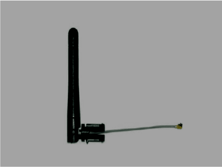
YOPGS2100MIE
Jun 21, 2014Ultra-Low Power Wi-Fi Module
Equipment Class
DTS - Digital Transmission System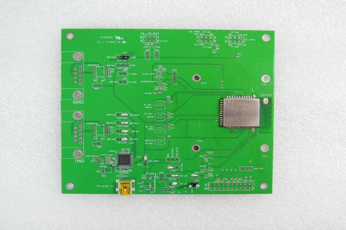
YOPGS1011MEPS
Aug 12, 2012WIFI MODULE
Equipment Class
DTS - Digital Transmission System
YOPGS1011MIES
Aug 12, 2012WIFI MODULE
Equipment Class
DTS - Digital Transmission System
YOPGS1011MEES
Aug 12, 2012WIFI MODULE
Equipment Class
DTS - Digital Transmission System