YRKDCS100RWireless USB Receiver
GENERAL TOOLS & INSTRUMENTS COMPANY LLC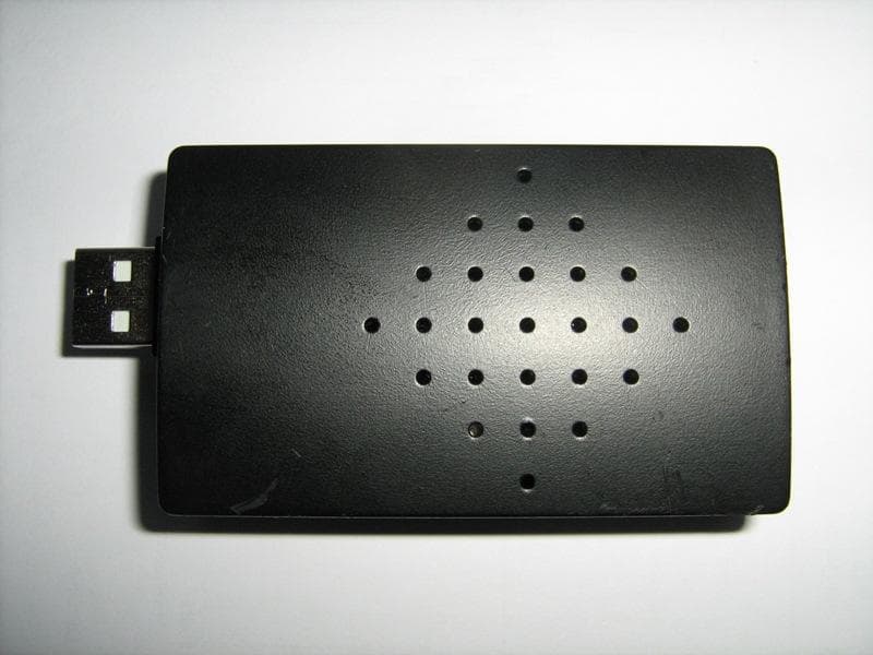
Click to zoom
Application Details
- Equipment Class
- JBP - Part 15 Class B Computing Device Peripheral
- Date of Grant
- Oct 05, 2010
- Application Purpose
- Original Equipment
- Date of Application
- Oct 05, 2010
- Equipment Note
- Wireless USB Receiver
- Country
- United States
Documents & Files
Document Text
Text extracted from the exhibit documents filed with the FCC. Open a document above to read the original.
Users Manual
Wireless USB Transmitter/ Wireless USB Receiver Model: DCS100T/DCS100R Operation Manual 1 Wireless USB Transmitter/ Wireless USB Receiver Model˖DCS100T/DCS100R Overview DCS100T/DCS100R USB wireless video inspection has been designed as a user friendly and economical way of solving hidden problems and increasing productivity. (eg. Inspect vent pipe and system of air conditioner, machine equipment, engine and so on). Wirelessly transmit the image signal between the unit and the receiver. Then the receiver transmit to computer by USB, which is facilitate for watching and collecting. The camera head is connected to the probe and with adjustable LED lights, which helps you to reach gaps and holes.The camera head has equipped with several accessories, which makes it flexible. The magnetic tip is used to pick up small metal objects. The mirror tip is easy to view the 90 ° angle. The hook is used to grab onto objects. The product has built-in polymer lithium battery, also could use AC adapter for charging with LED indication.The receiver has USB 2.0 interface, which is power supplied by USB to computer. It has the advantages of small sizeǃclear imageǃstable performanceǃeasy operation and portability. It is widely used in applications such as the industry, the building, the aviation, the vehicles maintenance. Safety Instructions Failure to follow the instructions listed below may result in electric shock or personal injury. ƔRead and understand all instructions prior to any operation. ƔDo not remove any labels from the tool. ƔKeep the work area clean and well lit, cluttered and dark areas may cause accidents. ƔDo not operate the tool with the presence of flammable/explosive gases. ƔDo not use the product around corrosive chemicals, which can ruin the picture quality. ƔKeep bystandersǃchildren and visitors away while operating the tool. ƔStay alert, watch what you are doing and use common sense. A moment of inattention will result in serious personal injury. ƔDo not overreach. Keep proper footing and balance all the time. ƔAlways wear protective eyewear. Dust maskǃnon-skid safety shoesǃhard hat or hearing protection must be used for appropriate conditions. ƔDo not place this product on any unstable cart or surface. The product may fall causing serial injury to a person or serious damage to the product. 2 ƔFor safety please always keep the video inspection away from any kind of liquid. Liquid increases the risk of electrical shock and damage to the product. ƔDo not use this device for personal or medical use. ƔThe unit is not shock-resistant. Do not use it as a hammer or drop it. Battery precautions Ɣ Please use the standard factory power adapter, otherwise will destroy the inside battery. ƔPlese completely exhaust the power for the first time. And we recommend full charging and full discharging for the first three times. And the charging time should not less than 12 hours. Full y activate the battery could play maximum capacity of the built-in battery. Ɣ The charging and discharging time differs because the different power from the factory. Ɣ Please always keep the charging connector away from the metal and oily objects. Ɣ Please fully charging the battery before it is not for use, to make sure the high performance while using. Ɣ Don’t compress and puncture the inside battery. Ɣ Please stop operating if the inside battery is broken. Ɣ Don’t throw the product into fire, which will cause explosion. ƔPlease dispose the battery properly. High temperature will cause the battery to explode. Please follow the local regulations for disposing the old batter y. Product Configures 3 1ˊCamera head and Probe ×1 2ˊThe inspecting grip ×1 3ˊMagnetic tip ×1 4ˊHook tip ×1 5ˊMirror tip ×1 6ˊReceiver ×1 7ˊDC adapter ×1 8ˊUSB cable ×1 9ˊSignal cable ×1 10ˊCD ROM ×1 Tool components AˊCamera protection BˊCamera head CˊProbe DˊProbe connector EˊChanel indication˄green˅——the flash times corresponding CH1̚CH4 Fˊ ——LED brightness decrease key Gˊ——LED brightness increase key HˊLow battery indication˄red˅ Iˊ /CH——Switch / exchange the wireless transmission chanel 4 JˊSignal cable interface KˊCharging interface LˊCharging light indicator MˊUSB interface NˊWorking light indicator OˊChanel light indicator——the flash times corresponding CH1̚CH4 PˊCH——Wireless chanel selection QˊSignal cable socket Operation Instructions ƔBattery Charging 1ǃConnect the DC cable to the tail of the handle L. 2ǃPlug the AC plugs to household power outlet. 3ǃThe LED L turns red ,means charging. 4ǃThe LED L turns green, means full y charging. 5ǃPull out the AC plug of adapter. ƔConnect the grip unit to camera head and probe The inspecting grip must be connected to the camera head and probe. To connect the probe to the grip, make sure the keyed ends are properly aligned. (Fig7). Once they are aligned, finger tighten the nut. ƽAccessories installation If you need to use the three accessories as FIG2 (magnetic tipǃhook tipǃmirror tip), please accord the steps followed to connect. As showed in Fig 8, hold the camera head .Slip the semicircle end of the accessory over the flats of camera head . Then rotate the accessory 90°to fix ,as shown in Fig9. ƔProgram installation Your computer should support the follows, then the recevier could connect to computer for use˖ • P4 1.4GHz or higher CPU • 256 MB RAM of system memory or above (recommended) • One available USB port (USB2.0) • Graphics Card (Must support DirectX 9.0c) • 1GB Free HD Space • CD-ROM Drive (For software installation) 5 • Microsoft Windows XP/vista/win7 1ǃPlace the CD, find the CD directory from "My Computer", click on "KC-Setup" file, install the drivers; 2ǃDirectly connect the receiver to computer ( or use cable), Windows will discover the new device, just one moment, there will be tips for normal use; 3ǃThe CD contains share software of AMCAP, you could copy to your computer and no need installation;You could another video software also; ƔOperation methods 1ǃHow to operate the grip˖ aǃPress /C…
Text truncated - open the document above for the full version.
External Photos
Document 57010088Report 02 Issue 1September 2010 Appendix External Photos COMMERCIAL-IN-CONFIDENCE FCC ID: YRKDCS100R COMMERCIAL-IN-CONFIDENCE Doc Number 57010088 Report 02 Issue 1 Page 1 of 2 COMMERCIAL-IN-CONFIDENCE Doc Number 57010088 Report 02 Issue 1 Page 2 of 2
ID Label/Location Info
FCC ID:YRKDCS100T MODEL:DCS100T Wireless USB Transmitter GENERAL TOOLS & INSTRUMENTS FCC ID:YRKDCS100R MODEL:DCS100R Wireless USB Receiver GENERAL TOOLS & INSTRUMENTS DCS100
Internal Photos
Document 57010088 Report 02 Issue 1September 2010 Appendix Internal Photos COMMERCIAL-IN-CONFIDENCE FCC ID: YRKDCS100R COMMERCIAL-IN-CONFIDENCE Doc Number 57010088 Report 02 Issue 1 Page 1 of 2 COMMERCIAL-IN-CONFIDENCE Doc Number 57010088 Report 02 Issue 1 Page 2 of 2
Test Report
Document 57010088 Report 02 Issue 1September 2010 Report On FCC Testing of the GENERAL TOOLS & INSTRUMENTS COMPANY LLC. Short Range Device Wireless USB Receiver DCS100R In accordance with FCC CFR 47 Part 15 Part B COMMERCIAL-IN-CONFIDENCE FCC ID: YRKDCS100R TÜV Product Service Ltd Beijing Branch 9 th Floor, Landmark Tower 2, No.8 North Dongsanhuan Road, Beijing 100004, P.R. China Tel: +86-10 6590 6186. W ebsite:www.tuv-sud.cn CO MME RCI AL-IN-CO NFI DE NCE Document 57010088 Report 02 Issue 1Page 1 of 21 COMMERCIAL-IN-CONFIDENCE REPORT ONFCC CRF 47 Parts 15 B: 2008 Testing of the GENERAL TOOLS & INSTRUMENTS COMPANY LLC. Short Range Device Wireless USB Receiver DCS100R Document 57010088 Report 02 Issue 1 September 2010 PREPARED FORGENERAL TOOLS & INSTRUMENTS COMPANY LLC. 80 WHITE STREET, NEW YORK,NY 10013, USA PREPARED BY Chen Jie Project Engineer APPROVED BY ZHANGChangxin Manager DATED28 Sep. 10 COMMERCIAL-IN-CONFIDENCE Document 57010088 Report 02 Issue 1Page 2 of 21 COMMERCIAL-IN-CONFIDENCE CONTENTS SectionPage No 1REPORT SUMMARY .............................................................................................................. 3 1.1Introduction ............................................................................................................................. 4 1.2Brief Summary of Results ........................................................................................................ 5 1.3Declaration of Build Status ....................................................................................................... 6 1.4Product Information ................................................................................................................. 7 1.5Test Conditions........................................................................................................................ 9 1.6Deviations From the Standard.................................................................................................. 9 1.7Modification Record ................................................................................................................. 9 1.8Alternative Test Site................................................................................................................. 9 2TEST DETAILS ..................................................................................................................... 10 2.1Conducted Emissions on Power Line ..................................................................................... 11 2.2Enclosure Radiated Emissions............................................................................................... 14 3TEST EQUIPMENT USED..................................................................................................... 17 3.1Test Equipment Used ............................................................................................................ 18 3.2Measurement Uncertainty ...................................................................................................... 19 4DISCLAIMERS AND COPYRIGHT ......................................................................................... 20 4.1Disclaimers and Copyright ..................................................................................................... 21 COMMERCIAL-IN-CONFIDENCE Document 57010088 Report 02 Issue 1Page 3 of 21 COMMERCIAL-IN-CONFIDENCE SECTION 1 REPORT SUMMARY FCC Testing of the GENERAL TOOLS & INSTRUMENTS COMPANY LLC. Short Range Device Wireless USB Receiver DCS100R in accordance with FCC CFR 47 Part 15B COMMERCIAL-IN-CONFIDENCE Document 57010088 Report 02 Issue 1Page 4 of 21 COMMERCIAL-IN-CONFIDENCE 1.1INTRODUCTION The information contained in this report is intended to show verification of the GENERAL TOOLS & INSTRUMENTS COMPANY LLC. Short Range Device Wireless USB Receiver DCS100R to the requirements of FCC CFR 47 Part 15B: 2008. Testing was carried out in support of an application for Grant of Equipment Authorisation of Short Range Device Wireless USB Receiver DCS100R. Objective To perform FCC Testing to determine the Equipment Under Test's (EUT’s) compliance with the Test Specification, for the series of tests carried out. ManufacturerGENERAL TOOLS & INSTRUMENTS COMPANY LLC. Model Number(s)Wireless USB Receiver DCS100R Serial Number(s)Engineering sample Antenna Gain0dBi Number of Samples Tested1 Test Specification/Issue/DateFCC CFR 47 Part 15B: 2008 Incoming Release Date Declaration of Build Status 24 August 2010 Start of Test31 August 2010 Finish of Test14 September 2010 Related Document(s)ANSI C63.4:2003 COMMERCIAL-IN-CONFIDENCE Document 57010088 Report 02 Issue 1Page 5 of 21 COMMERCIAL-IN-CONFIDENCE 1.2BRIEF SUMMARY OF RESULTS A brief summary of results in accordance with FCC CFR 47 Part 15B: 2008 is shown below. Configuration - Short Range Device W ireless USB Receiver Section FCC Clause Test DescriptionModeMod State ResultComments 2.115.107Conduct ed Emissions on Power LineIdle/r eceive0Pass 2.215.109Enclosure Radiated EmissionsIdle/r eceive0Pass COMMERCIAL-IN-CONFIDENCE Document 57010088 Report 02 Issue 1Page 6 of 21 COMMERCIAL-IN-CONFIDENCE 1.3DECLARATION OF BUILD STATUS MAIN EUT MANUFACTURING DESCRIPTION Short Range Device Wireless USB Receiver MANUFACTURER GENERAL TOOLS & INSTRUMENTS COMPANY LLC. TYPE DCS100R SERIAL NUMBE R Engineering sample COUNTRY OF ORIGIN America FCC ID YRKDCS100R TECHNICAL DESCRIPTION (a brief description of the intended use and operation) DCS100R is a Short Range Device Wireless USB Receiver MANUFACTURING DESCRIPTION The Wireless USB Receiver DCS100R was powered by Notebook Computer; Model Type: X200 Manufacturer: Lenovo Serial Number: 74595FC No responsibility will be accepted by TÜV Product Service Beijing Branch as to the accuracy of the information declared in this document by the manufacturer. COMMERCIAL-IN-CONFIDENCE Document 57010088 Report 02 Issue 1Page 7 of 21 COMMERCIAL-IN-CONFIDENCE 1.4PRODUCT INFORMATION 1.4.1Technical Description T…
Text truncated - open the document above for the full version.
Test Setup Photos
Document 57010088 Report 02 Issue 1September 2010 Appendix Setup Photos COMMERCIAL-IN-CONFIDENCE FCC ID: YRKDCS100R COMMERCIAL-IN-CONFIDENCE Doc Number 57010088 Report 02 Issue 1 Page 1 of 2 Radiation Emission Test Setup COMMERCIAL-IN-CONFIDENCE Doc Number 57010088 Report 02 Issue 1 Page 2 of 2 Conducted Emissions Test Setup
Contact Information
Applicant
Karen Kwong(Engineering and QA Manager)
Test Firm
DEKRA Testing and Certification (Suzhou) Co., Ltd.Jerry Pan
Technical Specifications
| # | Rule Parts | Frequency Range | Power Output |
|---|---|---|---|
| 1 | 15B | - | - |
Other Applications from GENERAL TOOLS & INSTRUMENTS COMPANY LLC
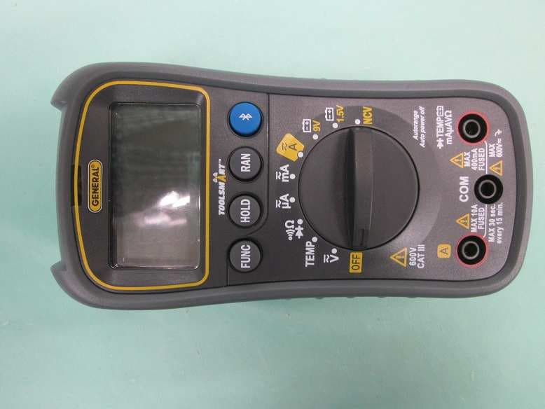
YRK-GTITS04
Jan 27, 2016ToolSmart BT Enabled Digital Multimeter
Equipment Class
DTS - Digital Transmission System
YRKDCS500R
May 19, 2014Wireless Video Receiver
Equipment Class
JBP - Part 15 Class B Computing Device Peripheral
YRKDCS500T
May 19, 2014Wireless Video Transmitter
Equipment Class
DXX - Part 15 Low Power Communication Device Transmitter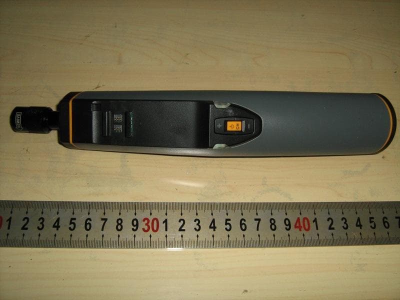
YRKESS400T
Oct 05, 2010Wireless Video Transmitter
Equipment Class
DXX - Part 15 Low Power Communication Device Transmitter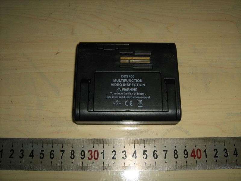
YRKDCS400R
Sep 30, 2010Wireless Video Receiver
Equipment Class
CYY - Communications Receiver used w/Pt 15 Transmitter