YWLLWST140002The RF Dongle, 2.4 GHz radio connected to a mobile tablet, is part of the qinetiq North AMerica LinWatch product line. The RF Dongle is used in conjunction with the setup tool for calibating LineWatch MVSS sensors.
QinetiQ North America, Inc.
Click to zoom
Application Details
- Equipment Class
- DSS - Part 15 Spread Spectrum Transmitter
- Date of Grant
- Aug 14, 2014
- Application Purpose
- Original Equipment
- Date of Application
- Aug 14, 2014
- Equipment Note
- The RF Dongle, 2.4 GHz radio connected to a mobile tablet, is part of the qinetiq North AMerica LinWatch product line. The RF Dongle is used in conjunction with the setup tool for calibating LineWatch MVSS sensors.
- Frequency Range
- 2465.00000000 - 2479.00000000
- Company
- QinetiQ North America, Inc.
- Country
- United States
Documents & Files
Document Text
Text extracted from the exhibit documents filed with the FCC. Open a document above to read the original.
Parts List/Tune Up Info
REV. DATE DRAWN CHK'ED APPRV A 9/3/2013 TJP JTB APK MANUF. PART #MANUF. CAGE CODEMANUFACTURERMANUF. ADDRESSMANUF. TELEPHONE SUPPLIER ADDRESSSUPPLIER TELEPHONESUPPLIER WEBSITESPEC. SHEET LINK SEE RB SEE RB SEE RB SEE RB SEE RB SEE RB REV SIZE CAGE B 5B2G7 SHEET: 1 OF 2 QNATSG1303 Form Rev B N/A NETWORKING, 2.45GHz, ANTENNA 1/4 WAVE 90 DEG SMA, LINX ANT-2.4-CW-RCS-SMA REFERENCE DATA SOURCEPREFERRED SUPPLIER N/A DRAWN: MANUF. WEBSITE NETWORKING, 2.45GHz, ANTENNA 1/4 WAVE 90 DEG SMA, LINX TITLE LINE 2SUPPLIER PART #SUPPLIER CAGE CODE REVISIONS N/A CHK'ED: APPRV: N/AN/A https://www.linxtec hnologies.com/resources/data-guides/ant-2.4-cw-rcs.pdf N/AANT-2.4-CW-RCS-SMA CATALOG ID DESCRIPTION GRANTS PASS, OR 97526USA(800) 736-6677 INTIAL RELEASE ANT-2.4-CW-RCS-SMALINX TECHNOLOGIES351T2 A 575 SE ASHLEY PL https://www.linxtec hnologies.com/en/home GOV. OR COMMERCIAL SPEC. # C000186 TITLE LINE 1 N/AN/A MANUFACTURER WEBSITE MANUFACTURER CATALOG REV SHEET 2 OF 2 NETWORKING, 2.45GHz, ANTENNA 1/4 WAVE 90 DEG SMA, LINX ANT-2.4-CW-RCS-SMA A QNATSG1303 Form Rev B C000186
Test Report
This report is for the exclusive use of Intertek's Client and is provided pursuant to the agreement between Intertek and its Client. Intertek's responsibility and liability are limited to the terms and conditions of the agreement. Intertek assumes no liability to any party, other than to the Client in accordance with the agreement, for any loss, expense or damage occasioned by the use of this report. Only the Client is authorized to permit copying or distribution of this report and then only in its entirety. Any use of the Intertek name or one of its marks for the sale or advertisement of the tested material, product or service must first be approved in writing by Intertek. The observations and test results in this report are relevant only to the sample tested. This report by itself does not imply that the material, product, or service is or has ever been under an Intertek certification program. Non-Specific EMC Report Shell Rev. January 2013 Client: QinetiQ North America,Technology Solutions Group, Model: PRD-1102196002 Page 1 of 128 EMISSIONS TEST REPORT Report Number: 101602013BOX-001b Project Number: G101602013 Report Issue Date: 05/29/2014 Product Designation: PRD-1102196002 Standards: CFR47 Part 15 Subpart C 15.247 (2014) CFR47 Part 15 Subpart B (2014) IC RSS-210 Issue 8 December 2010 Annex 8 IC RSS-Gen Issue 3 December 2010+Notice 2012-DRS0126 IC ICES-003 Issue 5 August 2012 IC RSS-102 Issue 4 March 2010 updated December 2010 Tested by: Client: Intertek Testing Services NA, Inc. 70 Codman Hill Road Boxborough, MA 01719 U.S.A QinetiQ North America,Technology Solutions Group 350 Second Ave. Waltham, MA 02451 U.S.A Report prepared by Report reviewed by Kouma Sinn / Sr. Project Engineer, EMC Vathana F. Ven / Sr. Project Engineer, EMC Intertek Report Number: 101602013BOX-001b Issued: 05/29/2014 Non-Specific EMC Report Shell Rev. January 2013 Page 2 of 128 Client: QinetiQ North America,Technology Solutions Group, Model: PRD-1102196002 1 Introduction and Conclusion The tests indicated in section 2.0 were performed on the product constructed as described in section 3.0. The remaining test sections are the verbatim text from the actual data sheets used during the investigation. These test sections include the test name, the specified test Method, a list of the actual Test Equipment Used, documentation Photos, Results and raw Data. No additions, deviations, or exclusions have been made from the standard(s) unless specifically noted. Based on the results of our investigation, we have concluded the product tested complies with the requirements of the standard(s) indicated. The results obtained in this test report pertain only to the item(s) tested. 2 Test Summary Section Test full name Result 3 Client Information -- 4 Description of Equipment Under Test -- 5 System Setup and Method -- 6 Maximum Peak Output Power, Human RF Exposure, & Duty Cycle CFR47 FCC Part 15 Subpart C (2014), Section 15.247 (b)(3) IC RSS-210 Issue 8 December 2010, A8.4 (4) IC RSS-102 Issue 4 March 2010 updated December 2010 Pass 7 Transmitter Radiated Spurious Emissions CFR47 FCC Part 15 Subpart C(2014), Section 15.247 (d) IC RSS-210 Issue 8 December 2010, A8.5 Pass 8 6 dB Bandwidth & 99% Power Bandwidth CFR47 FCC Part 15 Subpart C (2014), Section 15.247 (a)(2) IC RSS-210 Issue 8 December 2010, A8.2 (a) Pass 9 Power Spectral Density CFR47 FCC Part 15 Subpart C (2014), Section 15.247 (e) IC RSS-210 Issue 8 December 2010, A8.2 (b) Pass 10 Band-edge Compliance CFR47 FCC Part 15 Subpart C (2014), Section 15.247 (d) IC RSS-210 Issue 8 December 2010, A8.5 Pass 11 Digital Devices Radiated Spurious Emissions CFR47 FCC Part 15:2013 Subpart B Section 15.109 IC ICES-003 Issue 5 August 2012 Pass -- Receiver Radiated Spurious Emissions CFR47 FCC Part 15 Subpart B (2014), Section 15.109 IC RSS-Gen 3 December 2010, Section 6 Exempt, above 960 MHz 12 AC Mains Conducted Emissions CFR47 FCC Part 15 Subpart B (2014), Section 15.207 IC RSS-Gen Issue 3 December 2010, 7.2.2 (Table 2) Pass 13 Revision History -- Intertek Report Number: 101602013BOX-001b Issued: 05/29/2014 Non-Specific EMC Report Shell Rev. January 2013 Page 3 of 128 Client: QinetiQ North America,Technology Solutions Group, Model: PRD-1102196002 3 Client Information This EUT was tested at the request of: Company: QinetiQ North America, Technology Solutions Group 350 Second Ave. Waltham, MA 02451 U.S.A Contact: Dan. Binnun Telephone: (781) 684-3944 Fax: (781) 890-4084 Email: [email protected] 4 Description of Equipment Under Test Equipment Under Test Description Manufacturer Model Number Serial Number See below QinetiQ North America,Technology Solutions Group PRD-1102196002 Prototype Receive Date: 04/10/2014 & 05/17/2014 Received Condition: Good Type: Production Description of Equipment Under Test (provided by client) The RF Dongle is comprised of one printed circuit assembly which includes circuitry for handling communication with a mobile tablet as well as a radio for communication. The MSP430F47183IPZR is the main processing unit for the RF Dongle. The purpose of the RF Dongle is to facilitate the transmission of information from a Setup Tool to the connected mobile tablet. The mobile tablet then passes this information to a Collector, so the Feeder Meter Systems are calibrated. Communications The RF Dongle is connected via a USB port to a mobile tablet, and the information is translated by the USB UART IC. The device has one 2.4GHz ISM band radio that communicates with a Setup Tool. This radio system utilizes a -0.2 dBi 1/4-wave right angle antenna, and a Texas Instruments radio, which operates frequencies of 2.465-2.479 GHz and has 8 configurable receiver channels. Equipment Under Test Power Configuration Rated Voltage Rated Current Rated Frequency Number of Phases The RF Dongle uses an USB a connection with a mobile tablet to receive power. The USB connection delivers 5 VDC power to the USB UART IC, which then powers a voltage regulator at the same level. The voltag…
Text truncated - open the document above for the full version.
Test Setup Photos
(30‐1000 MHz) Radiated Emissions (1‐15 GHz) Z axis Radiated Emissions Test Setup (1‐15 GHz) Y axis Radiated Emissions Test Setup (1‐15 GHz) X axis Radiated Emissions Test Setup (15‐18 GHz) Hand Scan (18‐25 GHz) Hand Scan Antenna Port Conducted Test Setup
Contact Information
Applicant
David McDonald(Program Manager)
Technical Contact
Qinetiq, North America, Technical Solutions GroupChuck Deloid
[email protected]781 684 4606
350 Second Ave · Waltham, Massachusetts · United States
Test Firm
Intertek Testing Services NA Inc.Yaqing Liu
[email protected]978 635 8662
Technical Specifications
| # | Rule Parts | Frequency Range | Power Output |
|---|---|---|---|
| 1 | 15C | 2.46 GHz - 2.48 GHz | 22.40 mW |
Other Applications from QinetiQ North America, Inc.
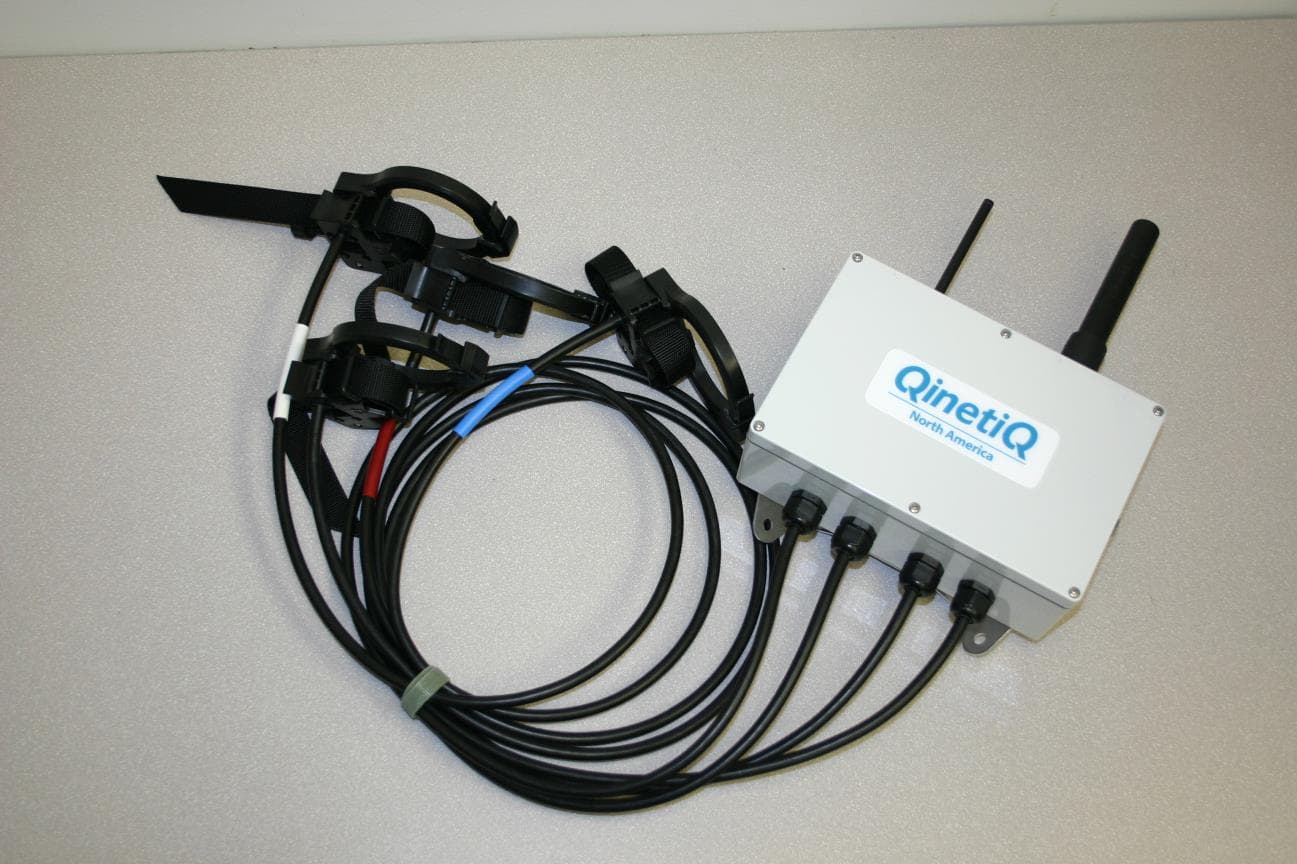
YWLLWLV140002
Oct 01, 2014Voltage and Current Measurement Clamp for PMT and LPT Transformers
Equipment Class
DTS - Digital Transmission System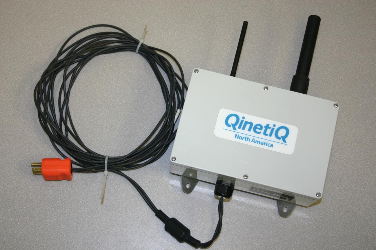
YWLLWMV140003
Oct 01, 2014Collects voltage and current readings from MVSS sensors
Equipment Class
DTS - Digital Transmission System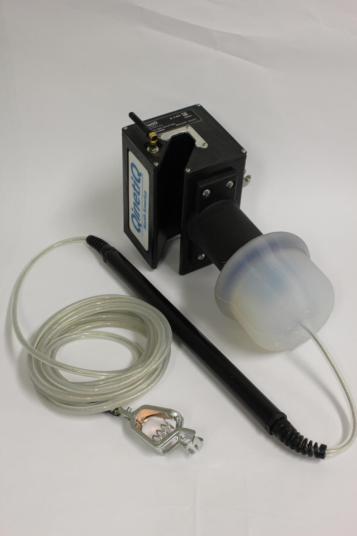
YWLLWST140001
May 20, 2014Setup Tool
Equipment Class
DXX - Part 15 Low Power Communication Device Transmitter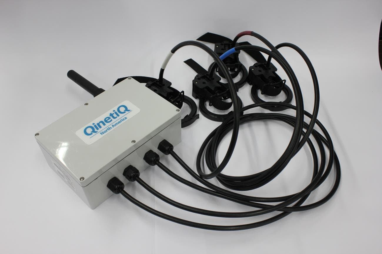
YWLLWLV140001
Feb 27, 2014Voltage and current reading clamp for overhead PMT and LPT transformers
Equipment Class
DTS - Digital Transmission System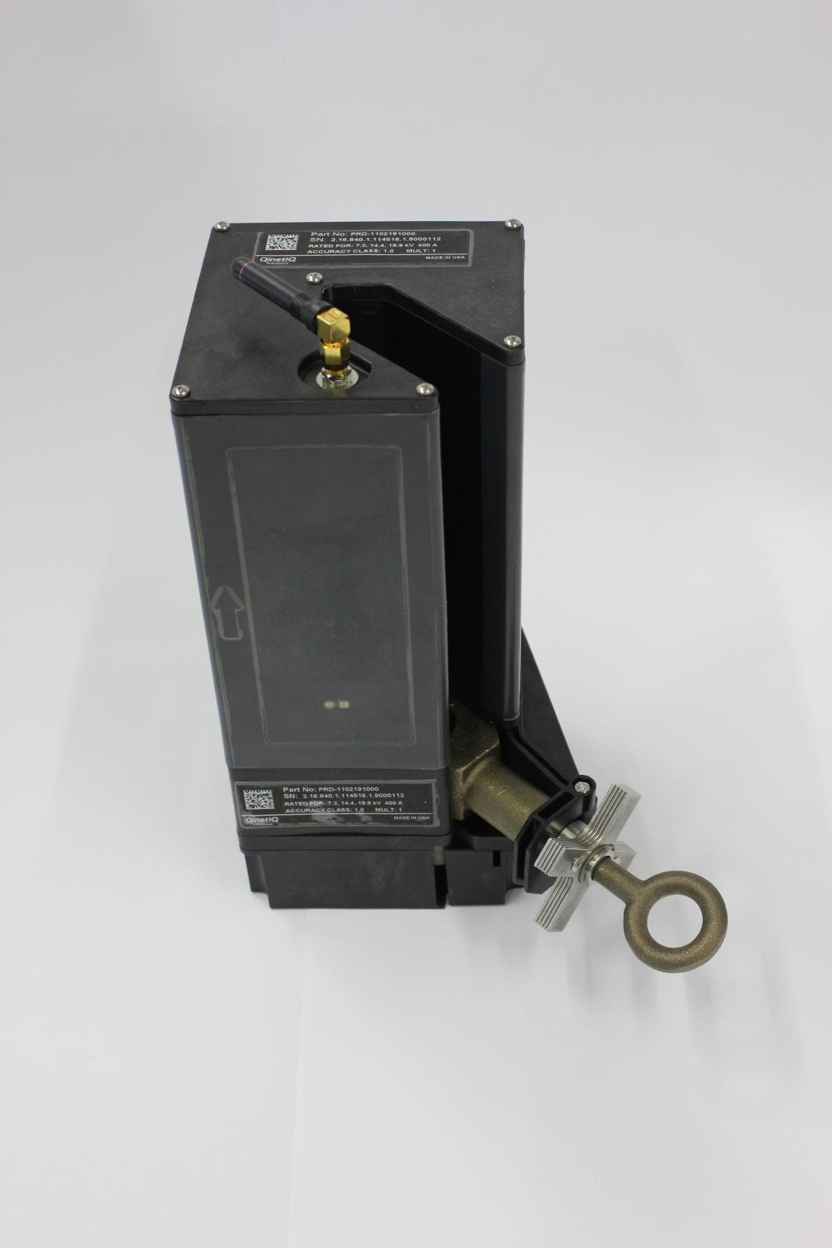
YWLLWMV140001
Feb 27, 2014Medium voltage power line clamping sensor
Equipment Class
DXX - Part 15 Low Power Communication Device Transmitter