YZO-00102Wireless Remote Unit
Wireless Seismic, Inc.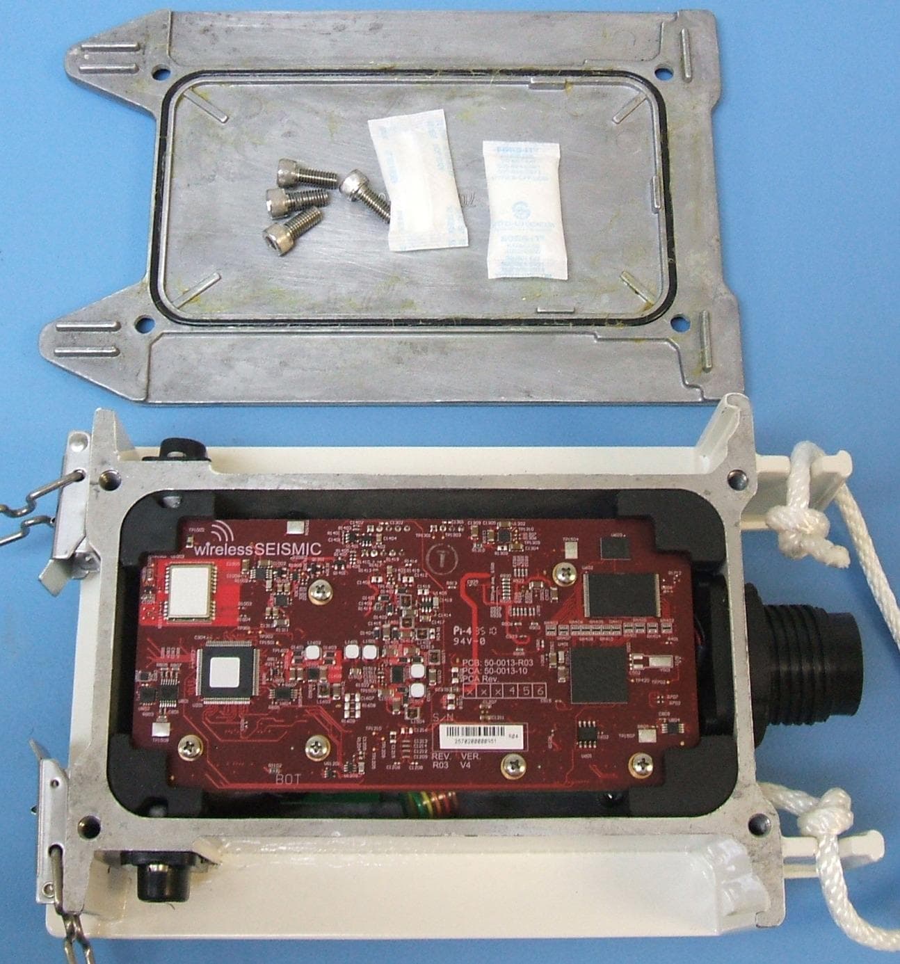
Click to zoom
Application Details
- Equipment Class
- DSS - Part 15 Spread Spectrum Transmitter
- Date of Grant
- Apr 08, 2012
- Application Purpose
- Original Equipment
- Date of Application
- Apr 08, 2012
- Equipment Note
- Wireless Remote Unit
- Frequency Range
- 2403.00000000 - 2475.00000000
- Company
- Wireless Seismic, Inc.
- Country
- United States
Documents & Files
Document Text
Text extracted from the exhibit documents filed with the FCC. Open a document above to read the original.
Users Manual
5Mbps Draft Real Time Matters Wireless Seismic, Inc. 13100 Southwest Freeway, Suite 150 Sugar Land, TX 77478 832.532.5080 RT 1000 Deployment Guide January 31, 2012 Part Number: 90-0004 R03.h 5Mbps Draft To order additional copies of this document, send an email to your sales representative requesting the following: Part Number: 90-0004-PDF Part Number: 90-0004-Paper © 2010-2012 Wireless Seismic, Inc. All rights reserved. All other brands, company names, product names, trademarks or service marks referenced in this material are the property of their respective owners, who may or may not be affiliated with, connected to, or sponsored by Wireless Seismic, Inc. Wireless Seismic, Inc.'s trademarks, registered trademarks or trade dress may not be used in connection with any product or service that is not the property of Wireless Seismic, Inc., in any manner that is likely to cause confusion among customers, or in any manner that disparages or discredits Wireless Seismic, Inc. The products and services described in this material may not be available in all regions. All information supplied in this Deployment Guide regarding weights, sizes, performance, functionality and other technical information of any kind is approximate and shall be taken as generally representing our products. We may modify our products, discontinue products or add new products at any time and without providing an update to this Deployment Guide. NOTHING CONTAINED IN THIS DEPLOYMENT GUIDE SHALL BE CONSIDERED A REPRESENTATION OR WARRANTY MADE BY WIRELESS SEISMIC, INC. (“WIRELESS SEISMIC”) CONCERNING ANY PRODUCT DESCRIBED HEREIN, OR OTHERWISE. EXCEPT FOR THE WARRANTIES THAT MAY BE PROVIDED IN A SEPARATE AGREEMENT BETWEEN YOU AND WIRELESS SEISMIC, WIRELESS SEISMIC MAKES NO REPRESENTATION OR WARRANTY OF ANY KIND AND NO WARRANTY, CONDITION OR REPRESENTATION, WHETHER EXPRESS, IMPLIED, ORAL OR STATUTORY, IS PROVIDED TO YOU OR ANY THIRD PARTY. WITHOUT LIMITING THE FOREGOING, WIRELESS SEISMIC EXPRESS EXCLUDES AND DISCLAIMS ANY WARRANTY, CONDITION OR REPRESENTATION: (1) OF MERCHANTABILITY, FITNESS FOR A PARTICULAR PURPOSE, TITLE, SATISFACTORY QUALITY, OR ARISING FROM A COURSE OF DEALING, USAGE, OR TRADE PRACTICE; (2) THAT ANY PRODUCTS (INCLUDING SOFTWARE) WILL BE FREE FROM INFRINGEMENT OR VIOLATION OF ANY RIGHTS, INCLUDING INTELLECTUAL PROPERTY RIGHTS, OF THIRD PARTIES; OR (3) THAT THE OPERATION OF ANY PRODUCT (INCLUDING SOFTWARE) WILL BE UNINTERRUPTED OR ERROR FREE. THIS DISCLAIMER AND EXCLUSION SHALL APPLY EVEN IF THE EXPRESS WARRANTIES HEREIN FAIL OF THEIR ESSENTIAL PURPOSE. 5Mbps Draft RT 1000 1.5.03 Deployment Guide R03.h © 2010-2012 Wireless Seismic, Inc. All rights reserved. Table of Contents 1.1. Overview . . . . . . . . . . . . . . . . . . . . . . . . . . . . . . . . . . . . . . . . . . 9 1.1 About this Guide . . . . . . . . . . . . . . . . . . . . . . . . . . . . . . . . . . . . . . 9 1.2 Who Should Use this Guide . . . . . . . . . . . . . . . . . . . . . . . . . . . . . . . 9 1.3 Related Documents . . . . . . . . . . . . . . . . . . . . . . . . . . . . . . . . . . . . 9 1.4 Getting Help . . . . . . . . . . . . . . . . . . . . . . . . . . . . . . . . . . . . . . . . . 9 2.2. Layout . . . . . . . . . . . . . . . . . . . . . . . . . . . . . . . . . . . . . . . . . . . .11 2.1 Prerequisites . . . . . . . . . . . . . . . . . . . . . . . . . . . . . . . . . . . . . . . . 11 2.2 Getting Ready . . . . . . . . . . . . . . . . . . . . . . . . . . . . . . . . . . . . . . . 11 2.3 Preparing the Equipment. . . . . . . . . . . . . . . . . . . . . . . . . . . . . . . . 13 2.4 Setting Up the Central Recording System . . . . . . . . . . . . . . . . . . . . 13 2.4.1 Setting up the Computer . . . . . . . . . . . . . . . . . . . . . . . . . . . . 13 2.4.2 Connecting to the Source Controller . . . . . . . . . . . . . . . . . . . . 13 2.4.3 Source Interface Cables . . . . . . . . . . . . . . . . . . . . . . . . . . . . . 20 2.4.4 Trigger Pin-Outs . . . . . . . . . . . . . . . . . . . . . . . . . . . . . . . . . . 22 2.5 Laying Out the Equipment . . . . . . . . . . . . . . . . . . . . . . . . . . . . . . . 25 2.5.1 Prerequisites. . . . . . . . . . . . . . . . . . . . . . . . . . . . . . . . . . . . . 25 2.5.2 Assembling the Ground Equipment . . . . . . . . . . . . . . . . . . . . . 26 2.5.3 Placing the WRU in the Field . . . . . . . . . . . . . . . . . . . . . . . . . . 28 2.5.4 Placing the BSU in the Field . . . . . . . . . . . . . . . . . . . . . . . . . . 30 3.3. Backhaul . . . . . . . . . . . . . . . . . . . . . . . . . . . . . . . . . . . . . . . . . .31 3.1 Overview. . . . . . . . . . . . . . . . . . . . . . . . . . . . . . . . . . . . . . . . . . . 31 3.2 Backhaul Components . . . . . . . . . . . . . . . . . . . . . . . . . . . . . . . . . 35 3.2.1 BSU Components . . . . . . . . . . . . . . . . . . . . . . . . . . . . . . . . . 35 3.2.1.1 BSU . . . . . . . . . . . . . . . . . . . . . . . . . . . . . . . . . . . . . . . 35 3.2.1.2 PoE Switch Unit . . . . . . . . . . . . . . . . . . . . . . . . . . . . . . . 36 3.2.1.3 Battery and Power Supply . . . . . . . . . . . . . . . . . . . . . . . . 37 3.2.1.4 Cables . . . . . . . . . . . . . . . . . . . . . . . . . . . . . . . . . . . . . . 38 3.2.2 Antennas . . . . . . . . . . . . . . . . . . . . . . . . . . . . . . . . . . . . . . . 39 3.2.3 Radio Kit Components . . . . . . . . . . . . . . . . . . . . . . . . . . . . . . 39 3.2.3.1 FM1100 Radio . . . . . . . . . . . . . . . . . . . . . . . . . . . . . . . . 40 3.2.3.2 FM3100 Radio . . . . . . . . . . . . . . . . . . . . . . . . . . . . . . . . 41 3.2.4 Mast Kit Components . . . . . . . . . . . . . . . . . . . . . . . . . . . . . . . 41 3.2.4.1 Mast . . . . . . . . . . . . . . . . . . . . . . . . . . . . . . . . . . . . . . . 42 3.2.4.2 Base . . . . . . . . . . . . . . . . . . . . . . . . . . . . . . . . . . . . . . . 42 3.2.4.3 Bag. . . . . . . . . . . . . . . . . . . . . . . . . . . . . . . . . . . . . . . . 45 3.2.4.4 Backpack Kit . . . . . …
Text truncated - open the document above for the full version.
Users Manual
5Mbps Draft R03.hRT 1000 1.5.0 Deployment Guide41 © 2010-2012 Wireless Seismic, Inc. All rights reserved. 3. Backhaul Backhaul Components 3.2.3.2 FM3100 Radio The FM3100 is used on the masts for the central backhaul unit and is shown in the following figure: 3.2.4 Mast Kit Components The following table lists the Mast Kit components. The remote and central backhauls use the same mast kit components: Figure 3–11 FM3100 Radio Table 3–4 Mast Kit Remote Backhaul Components ItemReference Mast (55-0008) “Mast” on page 42 Base (55-0007) “Base” on page 42 Base, weighted (70-0070)“Base” on page 42 Bag (70-0058) “Bag” on page 45 Ethernet Cable, 25 ft (65-0046) (2 each) “Cables” on page 38 Backpack Kit (15-0014) “Backpack Kit” on page 45 • 1 each backpack (70-0059) “Backpack Kit” on page 45 • 3 each guy lines, rope, orange, 15.25 meters (70- 0057) “Backpack Kit” on page 45 5Mbps Draft 42RT 1000 1.5.0 Deployment GuideR03.h © 2010-2012 Wireless Seismic, Inc. All rights reserved. 3. Backhaul Backhaul Components 3.2.4.1 Mast Lightweight, telescoping backhaul masts are used to elevate the backhaul components above obstructions and to enable radio communications to accommodate typical cross-line distances. The mast can be installed by a single person. The following figures show the mast components: 3.2.4.2 Base There are two base options; one that requires the use of guy wires for stabilization and one that uses weights for stabilization. • 3 each tent stake, steel, 12 in (70-0061) (hard ground stakes) “Backpack Kit” on page 45 • 3 each tent stake, plastic, orange, 16 in (70-0060) (soft ground stakes) “Backpack Kit” on page 45 • 5 ea nail, 12 in (70-0062)“Backpack Kit” on page 45 • 3 each guy line holder (70-0063) “Backpack Kit” on page 45 • 1 each hammer, 2.5 lb (70-0064)“Backpack Kit” on page 45 • 1 each pry bar, 15 in (70-0065)“Backpack Kit” on page 45 • 2 each flagging roll, orange (70-0066)“Backpack Kit” on page 45 • 1 each compass sighting (70-0067)“Backpack Kit” on page 45 • 5 each hose clamp, 2 in (70-0068)“Backpack Kit” on page 45 Figure 3–12 Mast (55-0008) Table 3–4 Mast Kit (cont.) Remote Backhaul Components ItemReference 5Mbps Draft R03.hRT 1000 1.5.0 Deployment Guide43 © 2010-2012 Wireless Seismic, Inc. All rights reserved. 3. Backhaul Backhaul Components The following figures show the base that utilizes guy-wires: Figure 3–13 Base (55-0007) 5Mbps Draft 44RT 1000 1.5.0 Deployment GuideR03.h © 2010-2012 Wireless Seismic, Inc. All rights reserved. 3. Backhaul Backhaul Components The following figure shows the assembled mast with the BSU in the foreground: The following figure shows the base that uses a weighted system. This base is optimal in urban or rocky environments: Figure 3–14 Assembled Backhaul Mast 5Mbps Draft R03.hRT 1000 1.5.0 Deployment Guide45 © 2010-2012 Wireless Seismic, Inc. All rights reserved. 3. Backhaul Backhaul Components 3.2.4.3 Bag The antenna mast bag is a rip stop nylon yellow bag, 11 inches x 70 inches with a handle and draw string at one end (see Figure 3–4 Backhaul Components Packed for Transport on page 35). 3.2.4.4 Backpack Kit The backpack is used to carry all of the equipment needed to install the mast and radios, and may also be use to carry the BSU. See “Mast Kit” on page 41 for a list of components (see Figure 3–4 Backhaul Components Packed for Transport on page 35). Figure 3–15 Base (70-0070) 5Mbps Draft 46RT 1000 1.5.0 Deployment GuideR03.h © 2010-2012 Wireless Seismic, Inc. All rights reserved. 3. Backhaul Configure the Radios 3.3 Configure the Radios The FMQuadro™ Web Interface is used to configure the radio channels. The radio licenses are pre-configured by Wireless Seismic, Inc. This section describes how to connect the radios to a computer and configure them. Check the radios before connecting them to any switch. 3.3.1 Create a Private Network Create a private network between the computer and the Fluidmesh radio. 1Prerequisites: ●Windows computer ●Browser with Adobe Flash ●AC Power ●PoE Injector ●Two Etherne t Cables 2Power on the computer. 3Connect the components (see Figure 3–16 Fluidmesh Radio Private Network on page 47): ●Plug the PoE injector into an AC outlet. ●Connect the computer to the PoE injector with an Ethernet cable. ●Connect the Fluidmesh radio to the PoE injector with an Ethernet cable. The radio powers up. ►FM1100 – Connect to LAN 1 ►FM3100 – There is only one connector NOTE The expected configuration in the RT 1000 system is as follows: FM1100 = mesh point (remote backhaul) FM3100 = mesh end (central backhaul) NOTE All Fluidmesh units are preconfigured with an IP address of 192.168.0.10. CAUTION Power up only one radio at a time. Never place two powered-up radios next to each other. It is possible to damage the radio receivers if multiple radios are powered up in close proximity. 5Mbps Draft R03.hRT 1000 1.5.0 Deployment Guide47 © 2010-2012 Wireless Seismic, Inc. All rights reserved. 3. Backhaul Configure the Radios 4Verify that the radio powers up. The LED indicators have the following meanings: 5Click the Windows Start icon. 6Select Control Panel. The Control Panel window opens. 7Select Network and Internet. Figure 3–16 Fluidmesh Radio Private Network Table 3–5 Fluidmesh Radio LEDs LEDStateDescription PowerOn / GreenOn whenever the radio has power LANOn / GreenOn whenever the radio has an Ethernet connection Signal Strength (1)On / Red Booting Core system Signal Strength (2)On / Orange Booting wireless system Signal Strength (3)On / Green Booting routing engine Signal Strength (4)On / Green Booting unit configuration 5Mbps Draft 48RT 1000 1.5.0 Deployment GuideR03.h © 2010-2012 Wireless Seismic, Inc. All rights reserved. 3. Backhaul Configure the Radios 8Select Network and Sharing Center. Figure 3–17 Control Panel, Network and Internet 5Mbps Draft R03.hRT 1000 1.5.0 Deployment Guide49 © 2010-2012 Wireless Seismic, Inc. All rights reserved. 3. Backhaul Configure the Radios 9In the left pane, select Change adapter settings. Figure 3–18…
Text truncated - open the document above for the full version.
Attestation Statements
Wireless Seismic, Inc. 361 Centennial Parkway, Suite 230 (p) 720.242.9916 Louisville, CO 80027 (f) 720.242.9987 November 17, 2010 PCTEST TCB/CB Division of PCTEST Engineering Lab., Inc. 6660-B Dobbin Road Columbia, MD 21045 To whom it may concern: We, the undersigned, hereby authorize PCTEST Engineering Laboratory Inc., to act on our behalf in all matters relating to applications for equipment authorization, including the signing of all documents relating to these matters. Any and all acts carried out by PCTEST Engineering Laboratory, Inc. on our behalf shall have the same effect as acts of our own. We also hereby certify that no party to this application is subject to a denial of benefits, including FCC benefits, pursuant to Section 5301 of the Anti-Drug Abuse Act of 1988, 21 U.S. C. 862. Sincerely, Shannon Adams VP Finance & Administration
Cover Letter(s)
Wireless Seismic, Inc. 361 Centennial Parkway, Suite 230 (p) 720.242.9916 Louisville, CO 80027 (f) 720.242.9987 December 19, 2011 Federal Communications Commission Authorization and Evaluation Division 7435 Oakland Mills Road, Columbia, MD 21046 RE: Request of Confidentiality for FCC ID: YZO-00102 To Whom It May Concern: Pursuant to Sections 0.457 and 0.459 of the Commission’s Rules (CFR 47), and Section 552 (b) (4) of the Freedom of Information Act, Wireless Seismic, Inc. hereby requests confidentiality and treatment of certain information accompanying this application. The materials contain trade secrets and proprietary information not customarily released to the public. The public disclosure of these matters might be harmful to the Applicant and provide unjustified benefits to its competitors. We are also hereby request Short-Term Confidentiality for 180 days after the grant as outlined in Public Notice DA 04-1705. This provision will give Wireless Seismic, Inc. temporary confidentiality of commercially sensitive information prior to product release. The requested Permanent and Temporary Confidential exhibits are listed as follows: PERMANENT AND SHORT-TERM CONFIDENTIAL LIST ExhibitDescription PERMANENT 1 Block Diagram 2 Operational Descriptions 3 Schematics SHORT-TERM CONFIDENTIAL 4 External Photos 5 Internal Photos 6 Test-Setup Photos 7 User’s Manual The Applicant understands that pursuant to Rule 0.457, disclosure of this application and all accompanying documentations, where applicable, will not be made public before the date of the Grant for this application. Wireless Seismic, Inc. Page 2 Sincerely, Travis R. Bird CFO Wireless Seismic, Inc.
ID Label/Location Info
REV APPROVAL DATE DESCRIPTION INITIAL RELEASE 5/9/11 PS 01 ECN 0284: UPDATED PER NEW FCC APPROVAL. 5/24/11 PS 02 ECN 0371: UPDATED WRU REV COLUMN FROM (04, 05) TO (04 - 06) 9/22/11 JO 03 UPDATED TABLE TO ADD NEW VERSION AND REVISION TBD PS 04 1. FONT: ARIAL OR SIMILAR SANS SE RIF FONT. FIRST LINE 11 POINT 2. AND FOLLOWING LINES 7 POINT FO NT SIZE. FONT SIZE MAY BE ADJUSTED IF NEEDED SO THAT TEXT FITS PROPERLY.FCC CERTIFICATION FOR A PARTICULAR WRU REVISION MUST 3. BE RECEIVED BEFORE THIS LABE L CAN BE PLACED ON THE WRU. SEE TABLE FOR COMPLETE FCC ID NUMBER 4. ASSEMBLY DRAWING.PLACE THE LABEL ON THE WRU AS SHOWN IN THE WRU NOTES: LABEL TO BE PRINTED ON 80-0010 LABEL OR EQUIVALENT. FCC ID NUMBER WRU VERSION, REV EFFECTIVE DATE YZO-00100 V1, R02, R03 2/2/11 YZO-00101 V1, R04 - R06 5/24/11 YZO-00102 V2, R01 FCC ID YZO-001__ This device complies with part 15 of theFCC Rules. Operation is subject to thefollowing two conditions: (1) This devicemay not cause harmful interference, and(2) this device must accept any interferencereceived, including interferencethat may cause undesired operation. TITLE: 04 DO NOT SCALE DRAWING 56-0001 SHEET 1 OF 1 5/9/11 P STEVENS UNLESS OTHERWISE SPECIFIED: SCALE: 1:1 DWG. NO. A SIZE NAME DATE MFG APPR.ENG APPR. CHECKEDDRAWN SEE NOTES SEE NOTES FINISHMATERIAL TOLERANCING PER: PROPRIETARY AND CONFIDENTIAL 5 4 3 2 1 INTERPRET GEOMETRIC 0.15 LABEL WRU FCC 0.3 IS PROHIBITED. TWO PLACE DECIMAL BEND ONE PLACE DECIMAL DIMENSIONS ARE IN MILLIMETERS TOLERANCES: ANGULAR: MACH THE INFORMATION CONTAINED IN THISDRAWING IS THE SOLE PROPERTY OFWIRELESS SEISMIC . ANY REPRODUCTION IN PART OR AS A WHOLE WITHOUT THE WRITTEN PERMISSION OFWIRELESS SEISMIC REV
RF Exposure Info
Reviewed by: FCC ID: YZO-00102 MAXIMUM PERMISSIBLE EXPOSURE (MPE) DATA REPORT Quality Manager Test Report S/N: Test Dates: EUT Type: 0Y1202030162.YZO 02/06/12 - 02/07/12 Wireless Remote Unit Page 1 of 7 © 2012 PCTEST Engineering Laboratory, Inc. REV 3.1MPE 02/09/09 Applicant Name: Date of Testing: Wireless Seismic, Inc. 02/06/12 - 02/07/12 361 Centennial Parkway, Suite 230 Test Site/Location: Louisville, CO 80027 PCTEST Lab, Columbia, MD, USA Test Report Serial No.: 0Y1202030162.YZO FCC ID: YZO-00102 APPLICANT: Wireless Seismic, Inc. EUT Type: Wireless Remote Unit FCC Rule Part(s): FCC Part 1 (§1.1310) and Part 2 (§2.1091) FCC Classification: PCS Licensed Transmitter (PCB) Test Procedure: OET Bulletin 65 The device bearing the FCC Identifier specified above has been shown to comply with the applicable technical standards as indicated in the measurement report and has been tested in accordance with the measurement procedures specified in FCC OET Bulletin 65 (See Test Report). These measurements were performed with no deviation from the standards. Test results reported herein relate only to the item(s) tested. I authorize and attest to the accuracy of data. All measurements reported herein were performed by me or were made under my supervision and are correct to the best of my knowledge and belief. I assume full responsibility for the completeness of these measurements and vouch for the qualifications of all persons taking them. PCTEST certifies that no party to this application has been subject to a denial of Federal benefits that includes FCC benefits pursuant to Section 5301 of the Anti-Drug Abuse Act of 1988, 21 U.S.C. 862. PCTEST ENGINEERING LABORATORY, INC. 6660-B Dobbin Road, Columbia, MD 21045 USA Tel. 410.290.6652 / Fax 410.290.6654 http://www.pctestlab.com RF EXPOSURE EVALUATION (MAXIMUM PERMISSIBLE EXPOSURE) Reviewed by: FCC ID: YZO-00102 MAXIMUM PERMISSIBLE EXPOSURE (MPE) DATA REPORT Quality Manager Test Report S/N: Test Dates: EUT Type: 0Y1202030162.YZO 02/06/12 - 02/07/12 Wireless Remote Unit Page 2 of 7 © 2012 PCTEST Engineering Laboratory, Inc. REV 3.1MPE 02/09/09 TABLE OF CONTENTS 1.0 RF EXPOSURE EVALUATION – MAXIMUM PERMISSIBLE EXPOSURE (MPE) .........................3 1.1 INTRODUCTION ................................................................................................................................... 3 1.2 EUT DESCRIPTION .............................................................................................................................. 3 1.3 MPE REQUIREMENTS OVERVIEW..................................................................................................... 4 1.4 PROCEDURE........................................................................................................................................ 5 1.5 SUMMARY OF RESULTS ..................................................................................................................... 6 2.0 CONCLUSION..................................................................................................................................7 Reviewed by: FCC ID: YZO-00102 MAXIMUM PERMISSIBLE EXPOSURE (MPE) DATA REPORT Quality Manager Test Report S/N: Test Dates: EUT Type: 0Y1202030162.YZO 02/06/12 - 02/07/12 Wireless Remote Unit Page 3 of 7 © 2012 PCTEST Engineering Laboratory, Inc. REV 3.1MPE 02/09/09 1.0 RF EXPOSURE EVALUATION – MAXIMUM PERMISSIBLE EXPOSURE (MPE) 1.1 Introduction This document is prepared on behalf of Wireless Seismic, Inc. to show compliance with the RF Exposure requirements as required in §1.1310 of the FCC Rules and Regulations and RSS-102 of Industry Canada. The limit for Maximum Permissible Exposure (MPE), specified in FCC §1.1310, is listed in Table 1-1. According to FCC §1.1310 and RSS-102: the criteria listed in the following table shall be used to evaluate the environmental impact of human exposure to radio-frequency (RF) radiation as specified in §1.1307(b). Frequency Range (MHz) Electric Field Strength (V/m) Magnetic Field Strength (A/m) Power Density (mW/cm 2 ) Average Time (Minutes) (A) Limits For Occupational / Control Exposures (f = frequency) 30-300 61.4 0.163 1.0 6 300-1500 ... ... f/300 6 1500-100,000 ... ... 5.0 6 (B) Limits For General Population / Uncontrolled Exposure (f = frequency) 30-300 27.5 0.073 0.2 30 300-1500 ... ... f/1500 30 1500-100,000 ... ... 1.0 30 Table 1-1. Limits for Maximum Permissible Exposure (MPE) 1.2 EUT Description The Wireless Seismic Wireless Remote Unit FCC ID: YZO-00102 is a frequency hopping spread spectrum transmitter operating in the 2.4GHz frequency range. For this MPE evaluation the device is set to transmit at maximum power in non-hopping mode from the supplied antenna and the RF exposure is evaluated. EUT: Model: RT1000 WRU Grantee: Wireless Seismic, Inc. FCC ID: YZO-00102 Antenna Gains: 9 dBi - Omnidirectional Antenna Reviewed by: FCC ID: YZO-00102 MAXIMUM PERMISSIBLE EXPOSURE (MPE) DATA REPORT Quality Manager Test Report S/N: Test Dates: EUT Type: 0Y1202030162.YZO 02/06/12 - 02/07/12 Wireless Remote Unit Page 4 of 7 © 2012 PCTEST Engineering Laboratory, Inc. REV 3.1MPE 02/09/09 1.3 MPE Requirements Overview Three different categories of transmitters are defined by the FCC in OET Bulletin 65. These categories are fixed installation, mobile, and portable and are defined as follows: o Fixed Installations: fixed location means that the device, including its antenna, is physically secured at a permanent location and is not able to be easily moved to another location. Additionally, distance to humans from the antenna is maintained to at least 2 meters. o Mobile Devices: a mobile device is defined as a transmitting device designed to be used in other than fixed locations and to be generally used in such a way that a separation distance of at least 20 centimeters is normally maintained between the transmitter's radiating structures and the body of the user or nearby persons. Transmitters designed to be used by consumers…
Text truncated - open the document above for the full version.
Test Setup Photos
Seismic Wireless, Inc. FCC ID: YZO-00102 Model: RT1000 WRU Test Set-Up Photos EUT Type: Wireless Remote Unit Page 1 of 1 © 2012 PCTEST Engineering Laboratory Inc. TEST SETUP PHOTOGRAPHS
Contact Information
Applicant
Bandele Adepoju(Sr. Engineer, Regulatory Compliance)
Technical Contact
PCTEST Engineering Lab., Inc.Randy Ortanez
[email protected]410-290-6652
6660-B Dobbin Road · Columbia, Maryland · United States
Test Firm
Element Materials Technology Washington DC LLCRandy Ortanez
Technical Specifications
| # | Rule Parts | Frequency Range | Power Output |
|---|---|---|---|
| 1 | 15C | 2.40 GHz - 2.48 GHz | 45.00 mW |
Other Applications from Wireless Seismic, Inc.
YZO-00106
Jun 24, 2014Wireless remote seismic disturbance sensor
Equipment Class
DSS - Part 15 Spread Spectrum Transmitter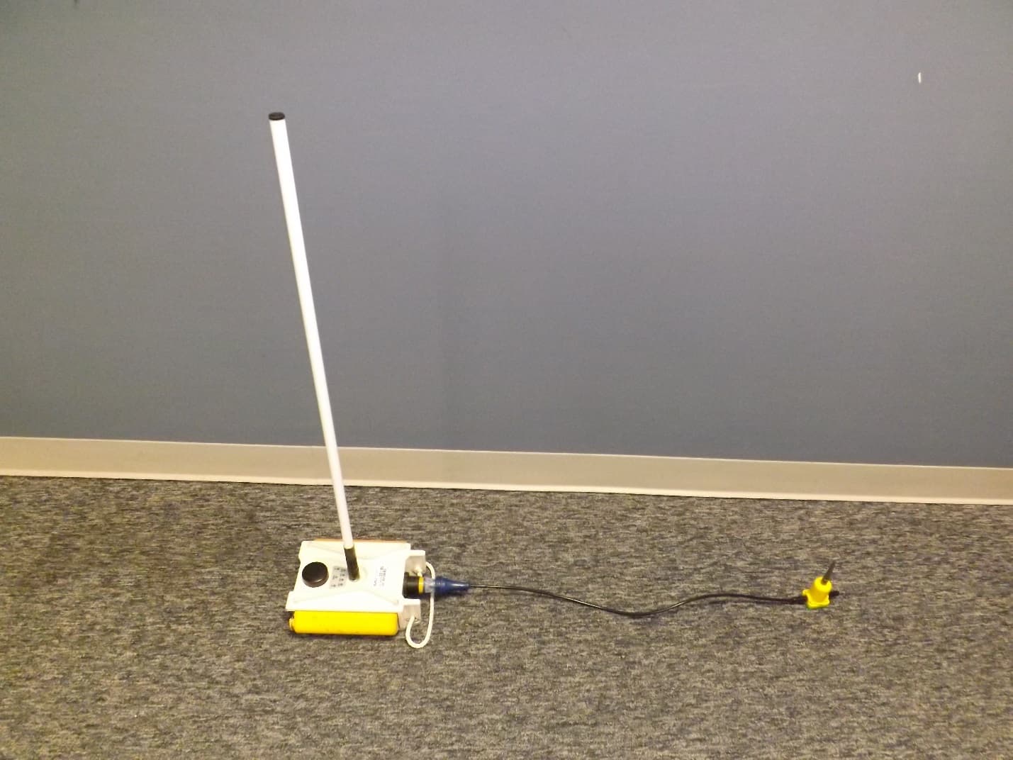
YZO-00105
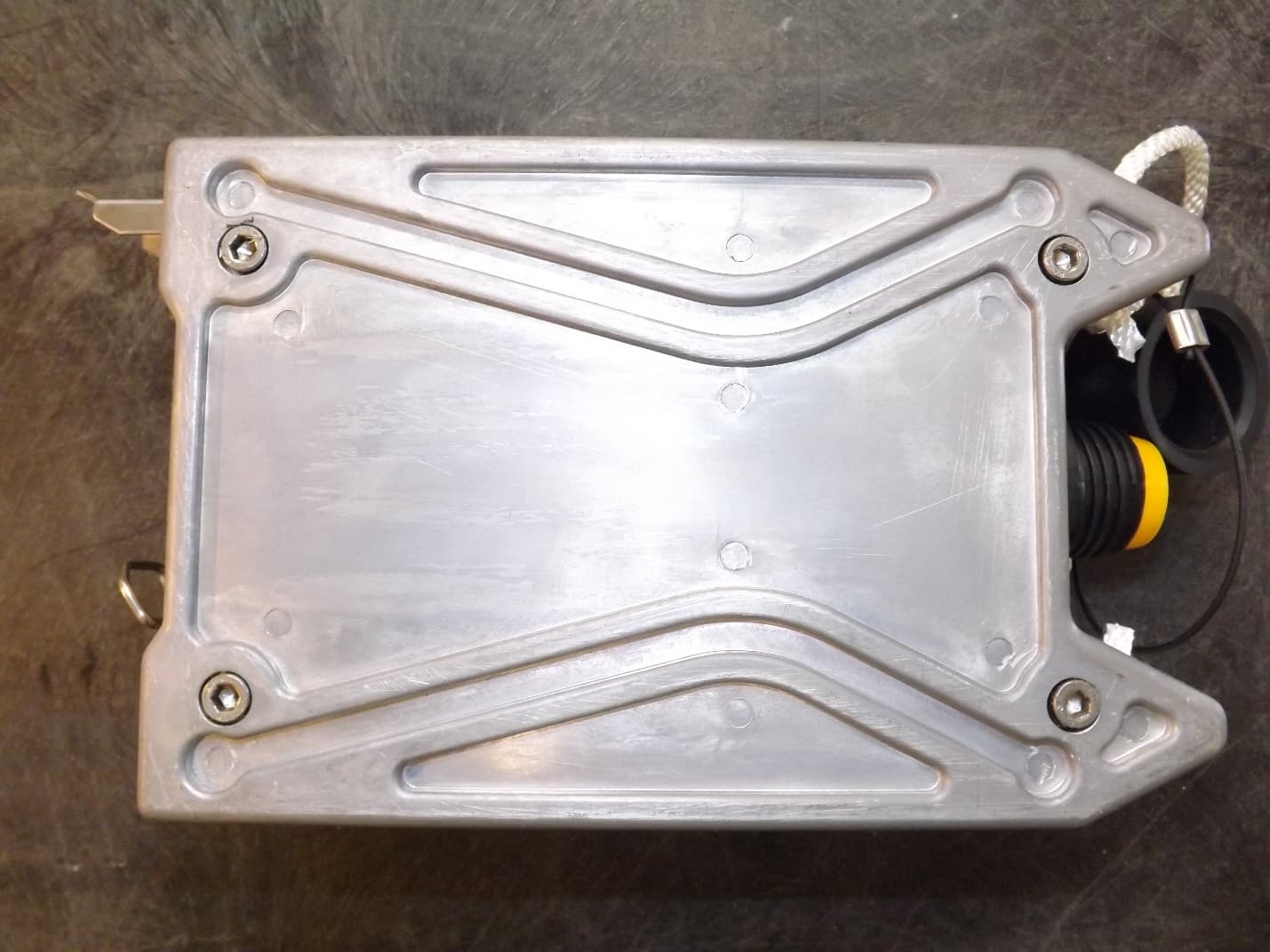
Apr 29, 2014Wireless Remote Unit
Equipment Class
DSS - Part 15 Spread Spectrum Transmitter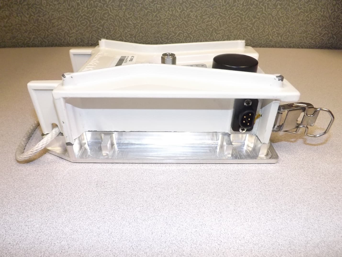
YZO-00104
Dec 30, 2013Wireless Seismic Sensor
Equipment Class
DSS - Part 15 Spread Spectrum Transmitter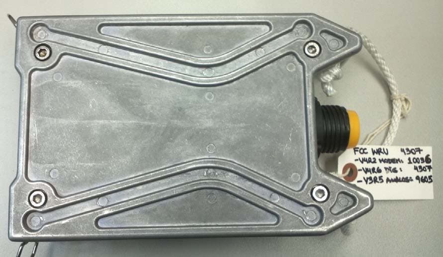
YZO-00103
Aug 06, 2012Wireless Remote Unit
Equipment Class
DSS - Part 15 Spread Spectrum Transmitter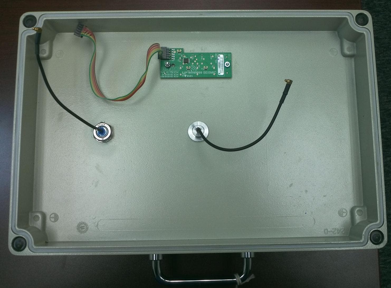
YZO-00600
Jul 26, 2012Line Interface Unit
Equipment Class
DSS - Part 15 Spread Spectrum Transmitter