YZO-00103Wireless Remote Unit
Wireless Seismic, Inc.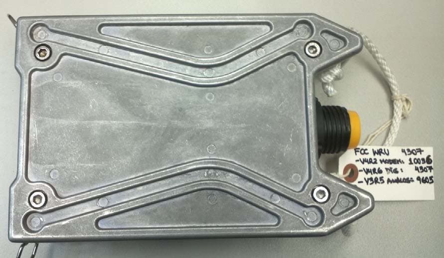
Click to zoom
Application Details
- Equipment Class
- DSS - Part 15 Spread Spectrum Transmitter
- Date of Grant
- Aug 06, 2012
- Application Purpose
- Original Equipment
- Date of Application
- Aug 06, 2012
- Equipment Note
- Wireless Remote Unit
- Frequency Range
- 2403.00000000 - 2475.00000000
- Company
- Wireless Seismic, Inc.
- Country
- United States
Documents & Files
Document Text
Text extracted from the exhibit documents filed with the FCC. Open a document above to read the original.
Users Manual
Draft RT System 2 Deployment Guide June 21, 2012 Part Number: 90-0018 R00.e Draft To order additional copies of this document, send an email to your sales representative requesting the following: Part Number: 90-0018-PDF Part Number: 90-0018-Paper Real Time Matters Corporate Headquarters: 13100 Southwest Freeway, Suite 150 Sugar Land, TX 77478 USA 832-532-5080 Regional Office: 1172 West Century Drive, Suite 200 Louisville, CO 80027 USA 720-242-9916 [email protected] www.wirelessseismic.com © 2010-2012 Wireless Seismic, Inc. All rights reserved. All other brands, company names, product names, trademarks or service marks referenced in this material are the property of their respective owners, who may or may not be affiliated with, connected to, or sponsored by Wireless Seismic, Inc. Wireless Seismic, Inc.'s trademarks, registered trademarks or trade dress may not be used in connection with any product or service that is not the property of Wireless Seismic, Inc., in any manner that is likely to cause confusion among customers, or in any manner that disparages or discredits Wireless Seismic, Inc. The products and services described in this material may not be available in all regions. Draft RT System 2 v2.0.03 Deployment Guide R00.e © 2010-2012 Wireless Seismic, Inc. All rights reserved. Table of Contents 1.1. Overview . . . . . . . . . . . . . . . . . . . . . . . . . . . . . . . . . . . . . . . . . . 9 1.1 About this Guide . . . . . . . . . . . . . . . . . . . . . . . . . . . . . . . . . . . . . . 9 1.2 Who Should Use this Guide . . . . . . . . . . . . . . . . . . . . . . . . . . . . . . . 9 1.3 Related Documents . . . . . . . . . . . . . . . . . . . . . . . . . . . . . . . . . . . . 9 1.4 Getting Help . . . . . . . . . . . . . . . . . . . . . . . . . . . . . . . . . . . . . . . . . 9 2.2. Layout . . . . . . . . . . . . . . . . . . . . . . . . . . . . . . . . . . . . . . . . . . . .11 2.1 Prerequisites . . . . . . . . . . . . . . . . . . . . . . . . . . . . . . . . . . . . . . . . 11 2.2 Getting Ready . . . . . . . . . . . . . . . . . . . . . . . . . . . . . . . . . . . . . . . 11 2.3 Preparing the Equipment. . . . . . . . . . . . . . . . . . . . . . . . . . . . . . . . 12 2.4 Laying Out the Equipment . . . . . . . . . . . . . . . . . . . . . . . . . . . . . . . 12 2.4.1 Prerequisites. . . . . . . . . . . . . . . . . . . . . . . . . . . . . . . . . . . . . 15 2.4.2 Assembling the Ground Equipment . . . . . . . . . . . . . . . . . . . . . 17 2.4.3 Placing the WRU in the Field . . . . . . . . . . . . . . . . . . . . . . . . . . 20 2.4.4 Placing the LIU in the Field . . . . . . . . . . . . . . . . . . . . . . . . . . . 22 3.3. Backhaul . . . . . . . . . . . . . . . . . . . . . . . . . . . . . . . . . . . . . . . . . .23 3.1 Overview. . . . . . . . . . . . . . . . . . . . . . . . . . . . . . . . . . . . . . . . . . . 23 3.2 Backhaul Components . . . . . . . . . . . . . . . . . . . . . . . . . . . . . . . . . 26 3.2.1 LIU Components . . . . . . . . . . . . . . . . . . . . . . . . . . . . . . . . . . 26 3.2.1.1 LIU . . . . . . . . . . . . . . . . . . . . . . . . . . . . . . . . . . . . . . . . 26 3.2.1.2 Battery and Power Supply . . . . . . . . . . . . . . . . . . . . . . . . 28 3.2.1.3 Cables . . . . . . . . . . . . . . . . . . . . . . . . . . . . . . . . . . . . . . 28 3.2.2 Antennas . . . . . . . . . . . . . . . . . . . . . . . . . . . . . . . . . . . . . . . 29 3.2.3 Radio Kit Components . . . . . . . . . . . . . . . . . . . . . . . . . . . . . . 29 3.2.3.1 FM1100 Radio . . . . . . . . . . . . . . . . . . . . . . . . . . . . . . . . 31 3.2.3.2 FM3100 Radio . . . . . . . . . . . . . . . . . . . . . . . . . . . . . . . . 31 3.2.3.3 Radio Install Kit . . . . . . . . . . . . . . . . . . . . . . . . . . . . . . . 32 3.2.4 Mast Kit Components . . . . . . . . . . . . . . . . . . . . . . . . . . . . . . . 33 3.2.4.1 Mast . . . . . . . . . . . . . . . . . . . . . . . . . . . . . . . . . . . . . . . 34 3.2.4.2 Base . . . . . . . . . . . . . . . . . . . . . . . . . . . . . . . . . . . . . . . 34 3.2.4.3 Bag. . . . . . . . . . . . . . . . . . . . . . . . . . . . . . . . . . . . . . . . 36 3.2.4.4 Backpack Kit . . . . . . . . . . . . . . . . . . . . . . . . . . . . . . . . . 36 3.3 Turn off the Windows Firewall . . . . . . . . . . . . . . . . . . . . . . . . . . . . 36 3.4 Configure the Radios . . . . . . . . . . . . . . . . . . . . . . . . . . . . . . . . . . 38 3.4.1 Create a Private Network . . . . . . . . . . . . . . . . . . . . . . . . . . . . 38 3.4.2 Setting NIC Priority . . . . . . . . . . . . . . . . . . . . . . . . . . . . . . . . 44 3.4.3 Configure the Radio . . . . . . . . . . . . . . . . . . . . . . . . . . . . . . . . 45 3.4.4 Restore your Network Settings . . . . . . . . . . . . . . . . . . . . . . . . 49 3.4.5 Using the Fluidmesh Interface to Scan . . . . . . . . . . . . . . . . . . . 49 3.4.6 Using the Fluidmesh Interface to Ping . . . . . . . . . . . . . . . . . . . 49 Draft 4RT System 2 v2.0.0 Deployment GuideR00.e © 2010-2012 Wireless Seismic, Inc. All rights reserved. Table of Contents 3.5 Setting up the Backhaul Equipment . . . . . . . . . . . . . . . . . . . . . . . . .49 3.6 Installing Two Radios on the Mast . . . . . . . . . . . . . . . . . . . . . . . . . .53 3.7 Removing the Backhaul Equipment . . . . . . . . . . . . . . . . . . . . . . . . .54 3.8 Use Cases or Example Deployments . . . . . . . . . . . . . . . . . . . . . . . .54 4.4. Demobilization . . . . . . . . . . . . . . . . . . . . . . . . . . . . . . . . . . . . . 58 4.1 Overview . . . . . . . . . . . . . . . . . . . . . . . . . . . . . . . . . . . . . . . . . . .58 4.2 Removing the WRU from the Field . . . . . . . . . . . . . . . . . . . . . . . . . .58 4.3 Disassemble the WRU . . . . . . . . . . . . . . . . . . . . . . . . . . . . . . . . . .59 5.5. Maintaining the Equipment. . . . . . . . . . . . . . . . . . . . . . . . . . . . 61 5.1 Units . . . . . . . . . . . . . . . . . . . . . . . . . . . . . …
Text truncated - open the document above for the full version.
Users Manual
Draft RT System 2 v2.0.058 Deployment Guide R00.e © 2010-2012 Wireless Seismic, Inc. All rights reserved. 4 4. Demobilization 4.1 Overview This chapter describes how to prepare (undeploy) the ground electronics for transport at the end of a project (demobilization). 4.2 Removing the WRU from the Field This section describes the process to ready the WRU for movement to a new physical location or to remove it in preparation for demobilization. To undeploy the WRU: 1Prerequisites: ●The WRU is assembled with battery, geophone, and antenna ●The WRU is in an active, transitional, or ready state 2Pick up the WRU and point the geophone connector end towards the sky as shown in the following figure. All of the LEDs illuminate: 3Place the unit flat in the transportation vehicle as shown in the following figure. The unit shuts down. The LEDs on the top of the unit are off. Figure 4–1 Power Off the Unit Draft R00.eRT System 2 v2.0.0 Deployment Guide59 © 2010-2012 Wireless Seismic, Inc. All rights reserved. 4. Demobilization Disassemble the WRU 4Optional: Remove batteries, antenna, or geophone as described in “Disassemble the WRU” on page 59. 4.3 Disassemble the WRU This section describes the process to disassemble the WRU prior to demobilization. To disassemble the WRU: 1Undeploy the equipment as described in “Removing the WRU from the Field” on page 58. 2Remove the antenna from the unit. 3Remove the geophone from the unit. 4Remove the batteries from the unit. ●Press the catch on the battery latch. ●Lift the lever, but do not lift the bail from the molded area on the battery. Figure 4–2 Undeployed Unit Draft 60RT System 2 v2.0.0 Deployment GuideR00.e © 2010-2012 Wireless Seismic, Inc. All rights reserved. 4. Demobilization Disassemble the WRU ●Continue to lift the lever using the bail to push the battery out of the connector. 5Secure the equipment in the transport vehicle. Figure 4–3 Removing the Battery Draft RT System 2 v2.0.061 Deployment Guide R00.e © 2010-2012 Wireless Seismic, Inc. All rights reserved. 5 5. Maintaining the Equipment 5.1 Units TBD 5.2 Antennas Ensure that the antennas are snug. TBD 5.3 Geophones Ensure that the geophone connection is clean and snug. TBD 5.4 Cautions TBD WARNING In order to comply with FCC radio frequency (RF) exposure requirements, the RT System 2 units must be installed so that a minimum separation distance of 20 cm is maintained between the antenna(s) and the body of all persons at all times during normal operation. WARNING AVERTISSEM ENT Afin de se conformer aux exigences de la FCC en matière d'exposition aux radiofréquences (RF), les unités RT System 2 doivent être installées de manière à garder en permanence une distance minimale de 20 cm entre la ou les antennes et le corps de toute personne en mode de fonctionnement normal. Draft RT System 2 v2.0.062 Deployment Guide R00.e © 2010-2012 Wireless Seismic, Inc. All rights reserved. 6 6. Troubleshooting and Tips 6.1 Best Practices This section provides some tips on working with the equipment. 6.1.1 24 Ah Batteries In order to maintain the best possible communication channel, observe the following tips: Place a fully charged 24 Ah battery on the backhaul every day. Keep extra 24 Ah batteries charged up at the staging area. Store 24 Ah batteries at the staging area when not in use. Deep discharging of the batteries can shorten their lifespan considerably. 6.1.2 LIU When temperature swings are extreme, or weather is severe, store the LIU boxes in the recording truck at night. 6.1.3 Urban Environments The following could impact your configuration in urban environments: You may need to use repeaters when crossing a road. You may need to extend the antenna with coaxial cable You may need to adjust WRU placement and antenna strength when crossing a road. You will need to consider the presence of power lines and buildings when placing WRUs and backhaul components. 6.1.4 Ethernet Cables Use CAT6 enhanced quality cables. CAUTION Do not allow the LIU battery to remain connected at a voltage of 22V or less. Damage to the equipment could occur. Draft R00.eRT System 2 v2.0.0 Deployment Guide63 © 2010-2012 Wireless Seismic, Inc. All rights reserved. 6. Troubleshooting and Tips Best Practices 6.1.5 Fiber Optic Cables The fiber optic cables have an environmentally-sealed connector. See the following figure for an illustration of how the connectors work: 6.1.6 Antennas When placing or selecting antennas in, consider the following: Figure 6–1 Fiber Optic Cable Connector Draft 64RT System 2 v2.0.0 Deployment GuideR00.e © 2010-2012 Wireless Seismic, Inc. All rights reserved. 6. Troubleshooting and Tips Troubleshooting In areas where there is a steep inclination, smaller gain antennas may provide a better signal. In areas where there is a steep inclination, try to reduce the inclination by going up or down at an angle rather than straight up or down. Use repeaters to cover overpass and steep inclination situations. If you need more signal strength, use an extender with a riser to elevate the antenna. This is the typical scenario with the LIU at the backhaul location. 6.2 Troubleshooting TBD 6.2.1 Backhaul Troubleshooting Flow This document shows the recommended steps to use when troubleshooting the backhaul. Indications that there are issues with the backhaul communication include the following: Missing pings Dropped line with a red arrow indicating the point of lost communication LIU unformed The following figures illustrate the recommended process flow when troubleshooting backhaul communication issues: 6.2.2 Fluidmesh Radios TBD TBD Figure 6–2 Troubleshooting – Check LIU TBD Figure 6–3 Troubleshooting – Check Fluidmesh Radios Draft R00.eRT System 2 v2.0.0 Deployment Guide65 © 2010-2012 Wireless Seismic, Inc. All rights reserved. 6. Troubleshooting and Tips Troubleshooting Table 6–1 Troubleshooting Fluidmesh Radios ProblemSolutions Not communicating• Try sending a ping command in a CMD window to the IP address of t…
Text truncated - open the document above for the full version.
Attestation Statements
Wireless Seismic, Inc. 361 Centennial Parkway, Suite 230 (p) 720.242.9916 Louisville, CO 80027 (f) 720.242.9987 November 17, 2010 PCTEST TCB/CB Division of PCTEST Engineering Lab., Inc. 6660-B Dobbin Road Columbia, MD 21045 To whom it may concern: We, the undersigned, hereby authorize PCTEST Engineering Laboratory Inc., to act on our behalf in all matters relating to applications for equipment authorization, including the signing of all documents relating to these matters. Any and all acts carried out by PCTEST Engineering Laboratory, Inc. on our behalf shall have the same effect as acts of our own. We also hereby certify that no party to this application is subject to a denial of benefits, including FCC benefits, pursuant to Section 5301 of the Anti-Drug Abuse Act of 1988, 21 U.S. C. 862. Sincerely, Shannon Adams VP Finance & Administration
Cover Letter(s)
Wireless S 361 Cente Louisville, A F A 74 C R T P S h a c in m co W gr S pr T fo P S C T ap m Seismic, Inc. ennial Parkway, , CO 80027 April 10, 201 ederal Com m Authorization 435 Oakland Columbia, M RE: Reque To Whom It M ursuant to S ection 552 ( ereby reques ccompanyin nformation n matters might ompetitors. We are also h rant as outlin eismic, Inc. rior to produ The requested ollows: PER M PERMANEN HORT-TER CONFIDEN The Applican pplication an made public b Suite 230 2 munications n and Evalua d Mills Road MD 21046 est of Confid May Concer ections 0.45 (b) (4) of the sts confident ng this applic not customar t be harmful hereby reque ned in Publi temporary c uct release. d Permanent MANENT A Exh NT 2 3 RM NTIAL 4 5 6 7 nt understand nd all accom before the da Commissio ation Divisio d, dentiality for rn: 57 and 0.459 e Freedom of tiality and tr cation. The m rily released l to the Appl est Short-Ter c Notice DA confidentiali t and Tempo AND SHOR hibit 1 Block 2 Opera 3 Schem 4 Exter 5 Intern 6 Test- 7 User’ ds that pursu mpanying doc ate of the Gr on on r FCC ID: Y of the Com f Information reatment of c materials con to the public licant and pr rm Confiden A 04-1705. T ty of comme orary Confid RT-TERM C k Diagram ational Desc matics rnal Photos nal Photos Setup Photo ’s Manual uant to Rule cumentation rant for this a YZO-00103 mmission’s R n Act, Wire certain inform ntain trade se c. The publi rovide unjust ntiality for 18 This provisio ercially sens ential exhibi CONFIDEN Descriptio criptions os 0.457, disclo ns, where app application. Rules (CFR 4 less Seismic mation ecrets and pr ic disclosure tified benefi 80 days after on will give W sitive inform its are listed NTIAL LIS on osure of this plicable, wil (p) 720.242.9 (f) 720.242.9 47), and c, Inc. roprietary of these ts to its r the Wireless mation d as T s ll not be 9916 9987 Wireless Seismic, Inc. Page 2 Sincerely, Travis R. Bird CFO Wireless Seismic, Inc.
Cover Letter(s)
Attachments: 10-0017 Label Locations.JPG; 56-0001 Rev05.PDF; Matls 80-0010 Revision 01 (Commercial).pdf; Brady Bondz B-423 label material.pdf; BRADY PTL-20-423.pdf; WS-0066 R00 b DRAFT RTS2 5 Theory Operational Description.pdf From: Jose Betancourt Sent: Friday, July 27, 2012 12:47 PM To: PCTEST TCB/CB Subject: RE: Questions Regarding FCC ID: YZO-00103 PCTEST TCB: Attached files containing the additional information you request: 1.The label and location document does not provide information as to how the FCC label will be permanently affixed to the EUT. Please provide this information per Part 15.19 of CFR Title 47. A. 10‐0017 Label Locations.JPG: shows the placement of the label on the LIU. B. 56‐0001 Rev05.PDF: shows WRU FCC label drawing. Note that it calls for ”LABEL TO BE PRINTED ON 80‐0010 LABEL OR EQUIVALENT” to be printed using an indelible thermal transfer printing process. C. Matls 80‐0010 Revision 01 (Commercial).pdf: shows materials used in the 80‐0010 lbel. Note that it calls for ”BRADY PTL‐20‐423 LABEL PRINTABLE WHITE POLYESTER” D.BRADY PTL‐20‐423.pdf: shows the spec for the “PERMANENT POLYESTER” label. As indicated, the label is designed to be permanently attached to the unit. E.Brady Bondz B‐423 label material.pdf: shows the technical data sheet for the label stock used. 2.Please provide an operational description document for the EUT per Part 2.1033 of CFR Title 47. A.WS‐0066 R00 b DRAFT RTS2 5 Theory Operational Description.pdf: this DRAFT theory of operations document contains the information concerning the functions of the devices in the RT System 2. This includes all such information regarding both the LIU (YZO‐00600) and WRU (YZO‐00103) units. 3. Not all sides of the EUT are shown in the external photographs document. Please revise to include additional photographs of all sides of the EUT. A.The external photo document is in the process of being updated. We will be sending it to you in the next couple of days. Please let me know if there are any remaining questions. Thanks. Regards, Jose’ Jose G. Betancourt From: PCTEST TCB/CB To: Mr.Jose G. Betancourt/ Wireless Seismic RE: FCC ID: YZO-00103 Applicant: Wireless Seismic Correspondence Reference Number: YZO0527 Confirmation Number: 1Y1204300527 Date of Original Email: July 23, 2012 Subject: Request for additional information In regards to your recent TCB application referenced above, we kindly request that you provide the following additional information. 1.The label and location document does not provide information as to how the FCC label will be permanently affixed to the EUT. Please provide this information per Part 15.19 of CFR Title 47. 3.Please provide an operational description document for the EUT per Part 2.1033 of CFR Title 47. 4.Not all sides of the EUT are shown in the external photographs document. Please revise to include additional photographs of all sides of the EUT. The item indicated above must be submitted before processing can continue on the above referenced application. Sincerely, PCTEST TCB PCTEST TCB/CB Tel. 1.410.290.6652 Fax. 1.410.290.6654 [email protected] www.pctesttcb.com Please consider the environment before printing this e-mail. This communication and its attachments contain information from PCTEST TCB/CB and are intended for the exclusive use of the recipient (s) named above. It may contain information that is confidential and/or legally privileged. Any unauthorized use that may compromise that confidentiality via distribution or disclosure is prohibited. Please notify the sender immediately if you receive this communication in error, and delete it from your computer system. Usage of PCTEST email addresses for non-business related activities is strictly prohibited. No warranty is made that the e-mail or attachment(s) are free from computer virus or other defect. Thank you.
External Photos
WRU 10-0017 Rev 01
ID Label/Location Info
FCC ID Label Location REV APPROVAL DATE DESCRIPTION INITIAL RELEASE 5/9/11 PS 01 ECN 0284: UPDATED PER NEW FCC APPROVAL. 5/24/11 PS 02 ECN 0371: UPDATED WRU REV COLUMN FROM (04, 05) TO (04 - 06) 9/22/11 JO 03 ECN 0501: UPDATED TABLE TO ADD NEW VERSION AND REVISION 4/9/12 PS 04 ECN 0555: UPDATED TABLE TO ADD NEW REVISION 6/14/12 JO 05 FCC ID YZO-001__ This device complies with part 15 of the FCC Rules. Operation is subject to the following two conditions: (1) This device may not cause harmful interference, and (2) this device must accept any interference received, including interference that may cause undesired operation. SEE TABLE FOR COMPLETE FCC ID NUMBER NOTES: LABEL TO BE PRINTED ON 80-0010 LABEL OR EQUIVALENT.1. FONT: ARIAL OR SIMILAR SANS SERIF FONT. FIRST LINE 11 POINT 2. AND FOLLOWING LINES 7 POINT FONT SIZE. FONT SIZE MAY BE ADJUSTED IF NEEDED SO THAT TEXT FITS PROPERLY. PLACE THE LABEL ON THE WRU AS SHOWN IN THE WRU 3. ASSEMBLY DRAWING. FCC ID NUMBERMODELVERSIONREVISIONEFFECTIVE DATE YZO-0010010-0001V102, 032/2/11 YZO-0010110-0001V104 - 065/24/11 YZO-0010210-0017V2PROTO YZO-0010310-0017V201, 02,03 05 DO NOT SCALE DRAWING 56-0001 SHEET 1 OF 1 5/9/11 P STEVENS UNLESS OTHERWISE SPECIFIED: SCALE: 1:1 DWG. NO. A SIZE NAME DATE MFG APPR. ENG APPR. CHECKED DRAWN SEE NOTES SEE NOTES FINISH INTERPRET GEOMETRIC TOLERANCING PER: PROPRIETARY AND CONFIDENTIAL 5 4 3 2 1 DIMENSIONS ARE IN MILLIMETERS TOLERANCES: ANGULAR: MACH BEND ONE PLACE DECIMAL 0.3 TWO PLACE DECIMAL 0.15 THE INFORMATION CONTAINED IN THIS DRAWING IS THE SOLE PROPERTY OF WIRELESS SEISMIC. ANY REPRODUCTION IN PART OR AS A WHOLE WITHOUT THE WRITTEN PERMISSION OF WIRELESS SEISMIC IS PROHIBITED. WRU FCC LABEL MATERIAL TITLE: REV
RF Exposure Info
Reviewed by: FCC ID: YZO-00103 MAXIMUM PERMISSIBLE EXPOSURE (MPE) DATA REPORT Quality Manager Test Report S/N: Test Dates: EUT Type: 0Y1204300604.YZO April 30, 2012 Wireless Remote Unit Page 1 of 6 © 2012 PCTEST Engineering Laboratory, Inc. REV 3.1MPE 02/09/09 Applicant Name: Date of Testing: Wireless Seismic, Inc. April 30, 2012 13100 Southwest Freeway, Suite 500 Test Site/Location: Sugarland, TX 77478 PCTEST Lab, Columbia, MD, USA USA Test Report Serial No.: 0Y1204300604.YZO FCC ID: YZO-00103 APPLICANT: Wireless Seismic, Inc. EUT Type: Wireless Remote Unit FCC Rule Part(s): FCC Part 1 (§1.1310) and Part 2 (§2.1091) FCC Classification: FCC Part 15 Frequency Hopping Spread Spectrum Transceiver (DSS) Test Procedure: OET Bulletin 65 The device bearing the FCC Identifier specified above has been shown to comply with the applicable technical standards as indicated in the measurement report and has been tested in accordance with the measurement procedures specified in FCC OET Bulletin 65 (See Test Report). These measurements were performed with no deviation from the standards. Test results reported herein relate only to the item(s) tested. I authorize and attest to the accuracy of data. All measurements reported herein were performed by me or were made under my supervision and are correct to the best of my knowledge and belief. I assume full responsibility for the completeness of these measurements and vouch for the qualifications of all persons taking them. PCTEST certifies that no party to this application has been subject to a denial of Federal benefits that includes FCC benefits pursuant to Section 5301 of the Anti-Drug Abuse Act of 1988, 21 U.S.C. 862. PCTEST ENGINEERING LABORATORY, INC. 6660-B Dobbin Road, Columbia, MD 21045 USA Tel. 410.290.6652 / Fax 410.290.6554 http://www.pctestlab.com RF EXPOSURE EVALUATION (MAXIMUM PERMISSIBLE EXPOSURE) Reviewed by: FCC ID: YZO-00103 MAXIMUM PERMISSIBLE EXPOSURE (MPE) DATA REPORT Quality Manager Test Report S/N: Test Dates: EUT Type: 0Y1204300604.YZO April 30, 2012 Wireless Remote Unit Page 2 of 6 © 2012 PCTEST Engineering Laboratory, Inc. REV 3.1MPE 02/09/09 TABLE OF CONTENTS 1.0 RF EXPOSURE EVALUATION – MAXIMUM PERMISSIBLE EXPOSURE (MPE) .........................3 1.1 INTRODUCTION ................................................................................................................................... 3 1.2 EUT DESCRIPTION .............................................................................................................................. 3 1.3 MPE REQUIREMENTS OVERVIEW..................................................................................................... 4 1.4 PROCEDURE........................................................................................................................................ 5 1.5 SUMMARY OF RESULTS ..................................................................................................................... 5 2.0 CONCLUSION..................................................................................................................................6 Reviewed by: FCC ID: YZO-00103 MAXIMUM PERMISSIBLE EXPOSURE (MPE) DATA REPORT Quality Manager Test Report S/N: Test Dates: EUT Type: 0Y1204300604.YZO April 30, 2012 Wireless Remote Unit Page 3 of 6 © 2012 PCTEST Engineering Laboratory, Inc. REV 3.1MPE 02/09/09 1.0 RF EXPOSURE EVALUATION – MAXIMUM PERMISSIBLE EXPOSURE (MPE) 1.1 Introduction This document is prepared on behalf of Wireless Seismic, Inc. to show compliance with the RF Exposure requirements as required in §1.1310 of the FCC Rules and Regulations and RSS-102 of Industry Canada. The limit for Maximum Permissible Exposure (MPE), specified in FCC §1.1310, is listed in Table 1-1. According to FCC §1.1310 and RSS-102: the criteria listed in the following table shall be used to evaluate the environmental impact of human exposure to radio-frequency (RF) radiation as specified in §1.1307(b). Frequency Range (MHz) Electric Field Strength (V/m) Magnetic Field Strength (A/m) Power Density (mW/cm 2 ) Average Time (Minutes) (A) Limits For Occupational / Control Exposures (f = frequency) 30-300 61.4 0.163 1.0 6 300-1500 ... ... f/300 6 1500-100,000 ... ... 5.0 6 (B) Limits For General Population / Uncontrolled Exposure (f = frequency) 30-300 27.5 0.073 0.2 30 300-1500 ... ... f/1500 30 1500-100,000 ... ... 1.0 30 Table 1-1. Limits for Maximum Permissible Exposure (MPE) 1.2 EUT Description The Wireless Seismic Model: 10-0017 is a Wireless Remote Unit containing a 2.4GHz Hopping Transmitter. For this MPE evaluation the device is set to transmit from the antenna and the RF exposure is evaluated. EUT: Model: 10-0017 Grantee: Wireless Seismic, Inc. FCC ID: YZO-00103 Antenna Gains: 9 dBi (Worst case antenna gain) Note: Several antennas will be deployed with the EUT, but the maximum antenna gain of 9dBi (Laird Technologies Model OD24M-9 Omnidirectional Antenna) is used herein for MPE evaluation. Reviewed by: FCC ID: YZO-00103 MAXIMUM PERMISSIBLE EXPOSURE (MPE) DATA REPORT Quality Manager Test Report S/N: Test Dates: EUT Type: 0Y1204300604.YZO April 30, 2012 Wireless Remote Unit Page 4 of 6 © 2012 PCTEST Engineering Laboratory, Inc. REV 3.1MPE 02/09/09 1.3 MPE Requirements Overview Three different categories of transmitters are defined by the FCC in OET Bulletin 65. These categories are fixed installation, mobile, and portable and are defined as follows: o Fixed Installations: fixed location means that the device, including its antenna, is physically secured at a permanent location and is not able to be easily moved to another location. Additionally, distance to humans from the antenna is maintained to at least 2 meters. o Mobile Devices: a mobile device is defined as a transmitting device designed to be used in other than fixed locations and to be generally used in such a way that a separation distance of at least 20 centimeters is normally maintained between the transmitter's radiating s…
Text truncated - open the document above for the full version.
Test Report
Reviewed by: FCC ID: YZO-00103 FCC Pt. 15.247 TEST REPORT (CERTIFICATION) Quality Manager Test Report S/N: Test Dates: EUT Type: 0Y1204300602.YZO April 30, 2012 Wireless Remote Unit Page 1 of 32 © 2012 PCTEST Engineering Laboratory, Inc. REV 1.6BTFI 01/04/11 Applicant Name: Date of Testing: Wireless Seismic, Inc. April 30, 2012 13100 Southwest Freeway, Suite 500 Test Site/Location: Sugarland, TX 77478 PCTEST Lab. Columbia, MD, USA USA Test Report Serial No.: 0Y1204300602.YZO FCC ID: YZO-00103 APPLICANT: Wireless Seismic, Inc. Application Type: Certification Model(s): 10-0017 EUT Type: Wireless Remote Unit Max. RF Output Power: 58.21 mW (17.65dBm) Conducted Frequency Range: 2403 – 2475MHz FCC Classification: FCC Part 15 Spread Spectrum Transmitter (DSS) FCC Rule Part(s): Part 15 Subpart C (15.247) IC Specification(s): RSS-210 Issue 8 This equipment has been shown to be capable of compliance with the applicable technical standards as indicated in the measurement report and was tested in accordance with the measurement procedures specified in ANSI C63.4-2003. Test results reported herein relate only to the item(s) tested. I attest to the accuracy of data. All measurements reported herein were performed by me or were made under my supervision and are correct to the best of my knowledge and belief. I assume full responsibility for the completeness of these measurements and vouch for the qualifications of all persons taking them. PCTEST certifies that no party to this application has been subject to a denial of Federal benefits that includes FCC benefits pursuant to Section 5301 of the Anti-Drug Abuse Act of 1988, 21 U.S.C. 862. PCTEST ENGINEERING LABORATORY, INC. 7185 Oakland Mills Road, Columbia, MD 21046 USA Tel. 410.290.6652 / Fax 410.290.6654 http://www.pctestlab.com MEASUREMENT REPORT FCC PART 15.247 / IC RSS-210 Reviewed by: FCC ID: YZO-00103 FCC Pt. 15.247 TEST REPORT (CERTIFICATION) Quality Manager Test Report S/N: Test Dates: EUT Type: 0Y1204300602.YZO April 30, 2012 Wireless Remote Unit Page 2 of 32 © 2012 PCTEST Engineering Laboratory, Inc. REV 1.6BTFI 01/04/11 TABLE OF CONTENTS FCC PART 15.247 MEASUREMENT REPORT...................................................................................3 1.0 INTRODUCTION......................................................................................................................................4 1.1 SCOPE....................................................................................................................................................... 4 1.2 PCTEST TEST LOCATION........................................................................................................................ 4 2.0 PRODUCT INFORMATION .....................................................................................................................5 2.1 EQUIPMENT DESCRIPTION..................................................................................................................... 5 2.2 EMI SUPPRESSION DEVICE(S)/MODIFICATIONS.................................................................................. 5 2.3 LABELING REQUIREMENTS .................................................................................................................... 5 3.0 DESCRIPTION OF TEST ........................................................................................................................6 3.1 EVALUATION PROCEDURE..................................................................................................................... 6 3.2 RADIATED EMISSIONS .................................…
Text truncated - open the document above for the full version.
Contact Information
Applicant
Bandele Adepoju(Sr. Engineer, Regulatory Compliance)
Technical Contact
PCTEST Engineering Lab., Inc.Randy Ortanez
[email protected]410-290-6652
6660-B Dobbin Road · Columbia, Maryland · United States
Test Firm
PCTEST Engineering Laboratory, Inc.Randy Ortanez
Technical Specifications
| # | Rule Parts | Frequency Range | Power Output |
|---|---|---|---|
| 1 | 15C | 2.40 GHz - 2.48 GHz | 58.00 mW |
Other Applications from Wireless Seismic, Inc.
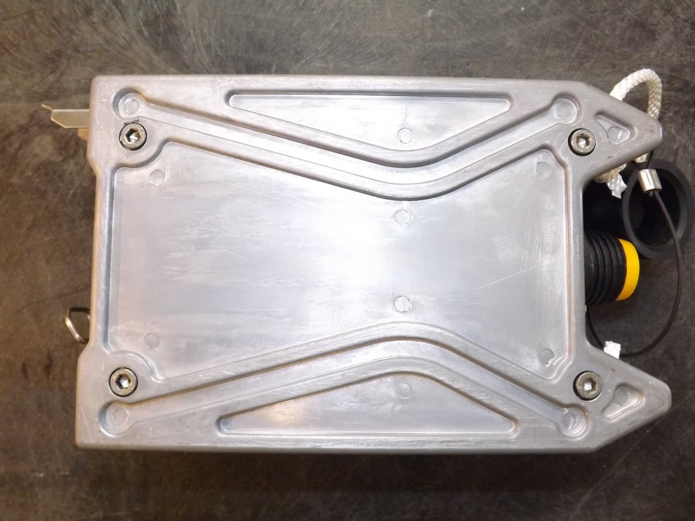
YZO-00106
Jun 24, 2014Wireless remote seismic disturbance sensor
Equipment Class
DSS - Part 15 Spread Spectrum Transmitter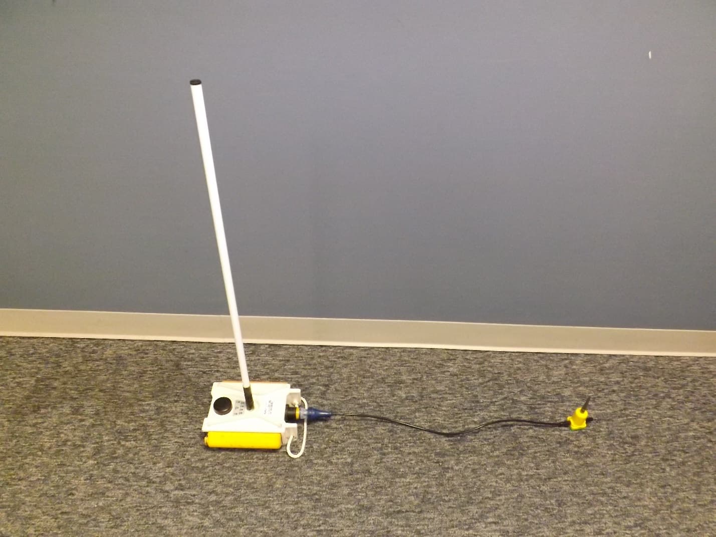
YZO-00105
Apr 29, 2014Wireless Remote Unit
Equipment Class
DSS - Part 15 Spread Spectrum Transmitter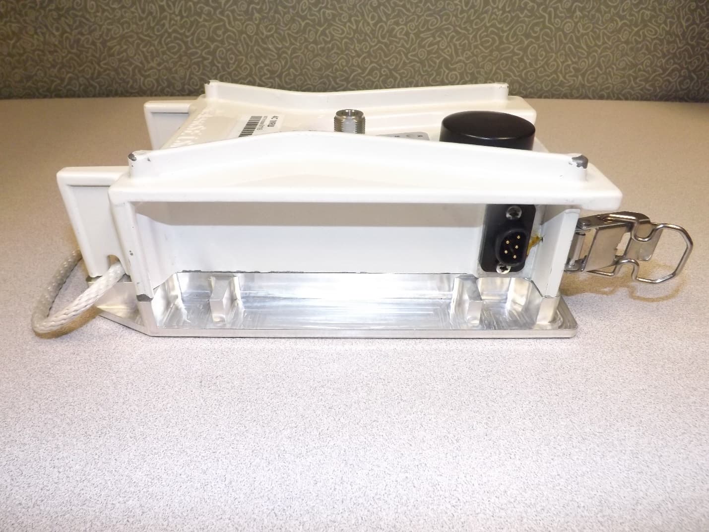
YZO-00104
Dec 30, 2013Wireless Seismic Sensor
Equipment Class
DSS - Part 15 Spread Spectrum Transmitter
YZO-00600
Jul 26, 2012Line Interface Unit
Equipment Class
DSS - Part 15 Spread Spectrum Transmitter
YZO-00102
Apr 08, 2012Wireless Remote Unit
Equipment Class
DSS - Part 15 Spread Spectrum Transmitter