YZO-00105Wireless Remote Unit
Wireless Seismic, Inc.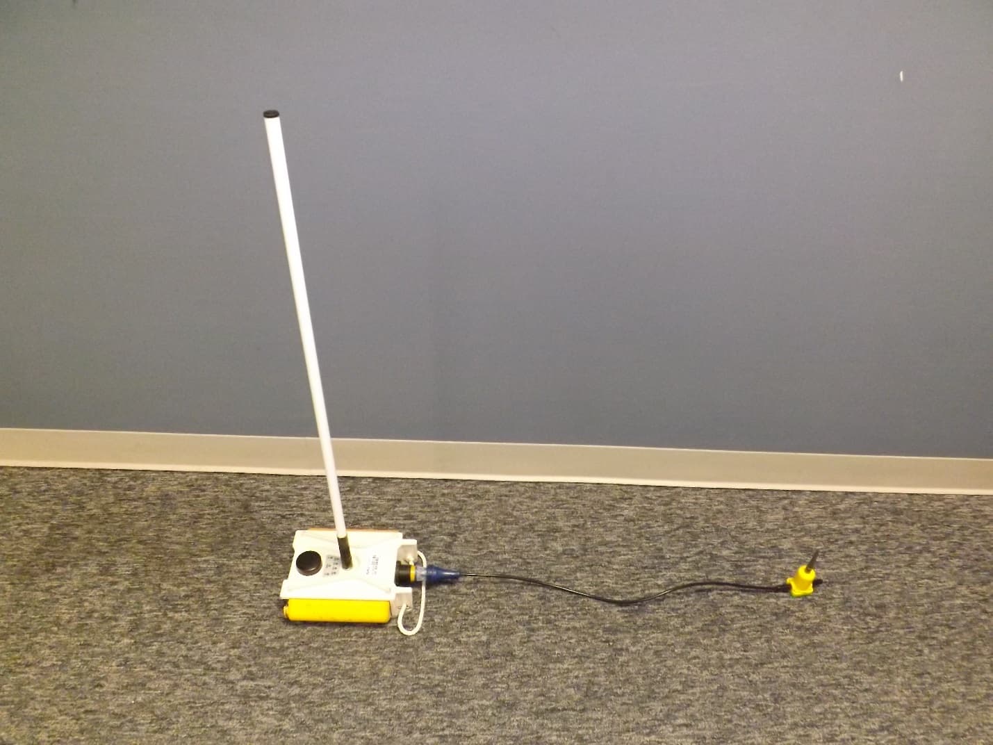
Click to zoom
Application Details
- Equipment Class
- DSS - Part 15 Spread Spectrum Transmitter
- Date of Grant
- Apr 29, 2014
- Application Purpose
- Original Equipment
- Date of Application
- Apr 29, 2014
- Equipment Note
- Wireless Remote Unit
- Frequency Range
- 2403.00000000 - 2475.00000000
- Company
- Wireless Seismic, Inc.
- Country
- United States
Documents & Files
Document Text
Text extracted from the exhibit documents filed with the FCC. Open a document above to read the original.
Users Manual
RT System 2 Deployment Guide April 15, 2014 Part Number: 90-0069 R01.i To order additional copies of this document, send an email to your sales representative requesting the following: iPart Number: 90-0069-PDF iPart Number: 90-0069-Paper Real Time Matters Corporate Headquarters: 13100 Southwest Freeway, Suite 150 x Sugar Land, TX 77478 USA x 832-532-5080 Regional Office: 1172 West Century Drive, Suite 200 x Louisville, CO 80027 USA x 720-242-9916 [email protected] x www.wirelessseismic.com © 2010-2014 Wireless Seismic, Inc. All rights reserved. All other brands, company names, product names, trademarks or service marks referenced in this material are the property of their respective owners, who may or may not be affiliated with, connected to, or sponsored by Wireless Seismic, Inc. Wireless Seismic, Inc.'s trademarks, registered trademarks or trade dress may not be used in connection with any product or service that is not the property of Wireless Seismic, Inc., in any manner that is likely to cause confusion among customers, or in any manner that disparages or discredits Wireless Seismic, Inc. The products and services described in this material may not be available in all regions. All information supplied in this document regarding weights, sizes, performance, functionality and other technical information of any kind is approximate and shall be taken as generally representing our products. We may modify our products, discontinue products or add new products at any time and without providing an update to this document. NOTHING CONTAINED IN THIS DOCUMENT SHALL BE CONSIDERED A REPRESENTATION OR WARRANTY MADE BY WIRELESS SEISMIC, INC. (“WIRELESS SEISMIC”) CONCERNING ANY PRODUCT DESCRIBED HEREIN, OR OTHERWISE. EXCEPT FOR THE WARRANTIES THAT MAY BE PROVIDED IN A SEPARATE AGREEMENT BETWEEN YOU AND WIRELESS SEISMIC, WIRELESS SEISMIC MAKES NO REPRESENTATION OR WARRANTY OF ANY KIND AND NO WARRANTY, CONDITION OR REPRESENTATION, WHETHER EXPRESS, IMPLIED, ORAL OR STATUTORY, IS PROVIDED TO YOU OR ANY THIRD PARTY. WITHOUT LIMITING THE FOREGOING, WIRELESS SEISMIC EXPRESS EXCLUDES AND DISCLAIMS ANY WARRANTY, CONDITION OR REPRESENTATION: (1) OF MERCHANTABILITY, FITNESS FOR A PARTICULAR PURPOSE, TITLE, SATISFACTORY QUALITY, OR ARISING FROM A COURSE OF DEALING, USAGE, OR TRADE PRACTICE; (2) THAT ANY PRODUCTS (INCLUDING SOFTWARE) WILL BE FREE FROM INFRINGEMENT OR VIOLATION OF ANY RIGHTS, INCLUDING INTELLECTUAL PROPERTY RIGHTS, OF THIRD PARTIES; OR (3) THAT THE OPERATION OF ANY PRODUCT (INCLUDING SOFTWARE) WILL BE UNINTERRUPTED OR ERROR FREE. THIS DISCLAIMER AND EXCLUSION SHALL APPLY EVEN IF THE EXPRESS WARRANTIES HEREIN FAIL OF THEIR ESSENTIAL PURPOSE. RT System 2 v2.33 Deployment Guide R01.i © 2010-2014 Wireless Seismic, Inc. All rights reserved. Table of Contents 1.1.Overview. . . . . . . . . . . . . . . . . . . . . . . . . . . . . . . . . . . . . . . . . . . . . . . . . . . . . . 10 1.1 About this Guide . . . . . . . . . . . . . . . . . . . . . . . . . . . . . . . . . . . . . . . . . . . 10 1.2 Who Should Use this Guide . . . . . . . . . . . . . . . . . . . . . . . . . . . . . . . . . . . . 10 1.3 Related Documents . . . . . . . . . . . . . . . . . . . . . . . . . . . . . . . . . . . . . . . . . 10 1.4 Getting Help . . . . . . . . . . . . . . . . . . . . . . . . . . . . . . . . . . . . . . . . . . . . . . 10 2.2.Layout. . . . . . . . . . . . . . . . . . . . . . . . . . . . . . . . . . . . . . . . . . . . . . . . . . . . . . . . 11 2.1 Prerequisites . . . . . . . . . . . . . . . . . . . . . . . . . . . . . . . . . . . . . . . . . . . . . . 11 2.2 Getting Ready . . . . . . . . . . . . . . . . . . . . . . . . . . . . . . . . . . . . . . . . . . . . . 11 2.3 Preparing the Equipment. . . . . . . . . . . . . . . . . . . . . . . . . . . . . . . . . . . . . . 12 2.4 Laying Out the Equipment. . . . . . . . . . . . . . . . . . . . . . . . . . . . . . . . . . . . . 12 2.4.1 Prerequisites . . . . . . . . . . . . . . . . . . . . . . . . . . . . . . . . . . . . . . . . . . 14 2.4.2 Assembling the Ground Equipment . . . . . . . . . . . . . . . . . . . . . . . . . . . 16 2.4.3 Placing the WRU in the Field. . . . . . . . . . . . . . . . . . . . . . . . . . . . . . . . 19 2.4.4 Placing the LIU in the Field. . . . . . . . . . . . . . . . . . . . . . . . . . . . . . . . . 22 2.5 WRU Anchor Plate . . . . . . . . . . . . . . . . . . . . . . . . . . . . . . . . . . . . . . . . . . 22 3.3.Backhaul. . . . . . . . . . . . . . . . . . . . . . . . . . . . . . . . . . . . . . . . . . . . . . . . . . . . . . 26 3.1 Overview . . . . . . . . . . . . . . . . . . . . . . . . . . . . . . . . . . . . . . . . . . . . . . . . 26 3.2 Backhaul Components . . . . . . . . . . . . . . . . . . . . . . . . . . . . . . . . . . . . . . . 31 3.2.1 LIU . . . . . . . . . . . . . . . . . . . . . . . . . . . . . . . . . . . . . . . . . . . . . . . . . 38 3.2.2 LIU Battery . . . . . . . . . . . . . . . . . . . . . . . . . . . . . . . . . . . . . . . . . . . 39 3.2.3 LIU and WRU Antennas . . . . . . . . . . . . . . . . . . . . . . . . . . . . . . . . . . . 39 3.2.4 Line Radios . . . . . . . . . . . . . . . . . . . . . . . . . . . . . . . . . . . . . . . . . . . 39 3.2.5 Recorder Radio . . . . . . . . . . . . . . . . . . . . . . . . . . . . . . . . . . . . . . . . . 42 3.2.6 Radio Antennas . . . . . . . . . . . . . . . . . . . . . . . . . . . . . . . . . . . . . . . . 44 3.2.7 Surge Protector Box . . . . . . . . . . . . . . . . . . . . . . . . . . . . . . . . . . . . . 44 3.2.8 Cable Assemblies . . . . . . . . . . . . . . . . . . . . . . . . . . . . . . . . . . . . . . . 45 3.2.9 Mast and Base . . . . . . . . . . . . . . . . . . . . . . . . . . . . . . . . . . . . . . . . . 49 3.2.9.1 Telescoping Mast . . . . . . . . . . . . . . . . . . . . . . . . . . . . . . . . . . . . 49 3.2.9.2 Base . . . . . . . . . . . . . . . . . . . . . . . . . . . . . . . . . . . . . . . . . . . . 49 3.3 Setting up the Backhaul . . . . . . . . . . . . . . . . . . . . . . . …
Text truncated - open the document above for the full version.
Attestation Statements
Wireless Seismic, Inc. 361 Centennial Parkway, Suite 230 (p) 720.242.9916 Louisville, CO 80027 (f) 720.242.9987 Request for Confidentiality Date: April 16, 2014 Subject: Confidentiality Request for: FCC ID: YZO-00105 Pursuant to FCC 47 CRF 0.457(d) and 0.459 and IC RSP-100, Section 10, the applicant requests that a part of the subject FCC application be held confidential. Type of Confidentiality Requested Exhibit Short Term Permanent Block Diagrams Short Term External Photos Short Term Permanent* 1 Internal Photos Short Term Permanent Operation Description/Theory of Operation Short Term Permanent Parts List & Placement/BOM Short Term Permanent Tune-Up Procedure Short Term Permanent Schematics Short Term Test Setup Photos Short Term Permanent* User’s Manual Short Term Permanent* Master Service Agreement *Note: Please refer to applicant’s Master Equipment and Services Agreement Wireless Seismic, Inc. has spent substantial effort in developing this product and it is one of the first of its kind in industry. Having the subject information easily available to "competition" would negate the advantage they have achieved by developing this product. Not protecting the details of the design will result in financial hardship. Permanent Confidentiality: The applicant requests the exhibits listed above as permanently confidential be permanently withheld from public review due to materials that contain trade secrets and proprietary information not customarily released to the public. Short-Term Confidentiality: The applicant requests the exhibits selected above as short term confidential be withheld from public view for a period of 180 days from the date of the Grant of Equipment Authorization and prior to marketing. This is to avoid premature release of sensitive information prior to marketing or release of the product to the public. Applicant is also aware that they are responsible to notify NTS in the event information regarding the product or the product is made available to the public. NTS will then release the documents listed above for public disclosure pursuant to FCC Public Notice DA 04-1705. NOTE for Industry Canada Applications: The applicant understands that until such time that IC distinguishes between Short Term and Permanent Confidentiality, either type of marked exhibit above will simply be marked Confidential when submitted to IC. Sincerely, By: Sr. Engineer Bandele Adepoju, NCE (Signature/Title) (Print name) Wireless Seismic, Inc. Page 2
Cover Letter(s)
Page 1 of 1 National Technical Systems TCB 41039 Boyce Road Fremont, CA, 94538 FCC ID: YZO-00105 IC: 10081A-WSI00106 To whom it may concern: The enclosed documents constitute a formal submittal and application for Equipment Authorization for a 2.4GHz FHSS radio pursuant to the following rules: Subpart C of Part 15 of FCC Rules (CFR 47), Intentional Radiators RSS-Gen Issue 3, December 2010, “General Requirements and Information for the Certification of Radiocommunication Equipment” RSS-210, Issue 8, December 2010, “Low-power Licence-exempt Radiocommunication Devices (All Frequency Bands): Category I Equipment” National Technical System, as duly authorized agent prepared this submittal. A copy of the letter of our appointment as agent is included with the application. If there are any questions or if further information is needed, please contact Elliott Laboratories for assistance. Sincerely, Mark Hill Staff Engineer
External Photos
WRU, Model 01‐0001, FCC ID: YZO‐00105 Page 1 of 10 External Photos Wireless Seismic Remote Unit (WRU) WRU, Model 01-0001 WRU, Model 01‐0001, FCC ID: YZO‐00105 Page 2 of 10 WRU, Model 01-0001 WRU, Model 01‐0001, FCC ID: YZO‐00105 Page 3 of 10 WRU, Model 01-0001 WRU, Model 01‐0001, FCC ID: YZO‐00105 Page 4 of 10 WRU, Model 01-0001 WRU, Model 01‐0001, FCC ID: YZO‐00105 Page 5 of 10 WRU, Model 01-0001 WRU, Model 01‐0001, FCC ID: YZO‐00105 Page 6 of 10 WRU, Model 01-0001 WRU, Model 01‐0001, FCC ID: YZO‐00105 Page 7 of 10 WRU, Model 01-0001 WRU, Model 01‐0001, FCC ID: YZO‐00105 Page 8 of 10 WRU, Model 01-0001 WRU, Model 01‐0001, FCC ID: YZO‐00105 Page 9 of 10 WRU, Model 01-0001 WRU, Model 01‐0001, FCC ID: YZO‐00105 Page 10 of 10 WRU, Model 01-0001
ID Label/Location Info
50.0 25.0 FCC ID NUMBER MODEL VERSION REVISION YZO-00105 01-0001 that may cause undesired operation.This device complies with part 15 of theFCC Rules. Operation is subject to thefollowing two conditions: (1) This devicemay not cause harmful interference, and(2) this device must accept any interferencereceived, including interference FCC ID: YZO-00105 NOTES: LABEL TO BE PRINTED ON BRADY THERMAL TRANSFER 1. POLYESTER LABEL P/N PTL-20-423 OR EQUIVALENT.FONT: ARIAL OR SIMILAR SANS SE RIF FONT. FIRST LINE 11 POINT 2. AND FOLLOWING LINES 7 POINT FO NT SIZE. FONT SIZE MAY BE ADJUSTED IF NEEDED SO THAT TEXT FITS PROPERLY.PLACE THE LABEL ON THE WRU AS SHOWN IN THE WRU 3. ASSEMBLY DRAWING. PROTO FCC G. SALDAÑA MATERIAL UNLESS OTHERWISE SPECIFIED: TITLE: 4/29/14 DO NOT SCALE DRAWING SHEET 1 OF 1 IS PROHIBITED. LABEL SCALE: 1:1 DWG. NO. A SIZE NAME DATE MFG APPR.ENG APPR. SEE NOTES SEE NOTES TOLERANCING PER: PROPRIETARY AND CONFIDENTIAL 5 4 3 2 FINISH WRU FCC DRAWN 1 BEND CHECKED 0.15 0.3 ONE PLACE DECIMAL INTERPRET GEOMETRIC TWO PLACE DECIMAL DIMENSIONS ARE IN MILLIMETERS TOLERANCES: ANGULAR: MACH THE INFORMATION CONTAINED IN THISDRAWING IS THE SOLE PROPERTY OFWIRELESS SEISMIC . ANY REPRODUCTION IN PART OR AS A WHOLE WITHOUT THE WRITTEN PERMISSION OFWIRELESS SEISMIC REV
ID Label/Location Info
TLS 2200®/TLS PC Link™ BradyBondz™ Labels - # PTL-20-423 APPLICATION(S): Bottles, Circuit Board & Component ID, Conical Tube, Deep Well Plate, Laboratory Identification, Petri Dish, Through Hole - Top SIZE: 2.000" W x 1.000" H (50.800 mm W x 25.400 mm H) MATERIAL:Permanent Polyester QTY/UOM:100/Roll CATALOG #:PTL-20-423 PRODUCT #:18375 $22.10 MSRP ($US) QTY: 1 OV ERV IEWSPECIFICA TIONS Description for TLS 2200®/TLS PC Link™ BradyBondz™ Labels BradyBondz™ Labels for the TLS 2200® & TLS-PC Link™ Thermal Transfer Portable Printers. Please Note: This material is UL, CSA & AGA approved with its respective ribbon. See the "Recommended Ribbon Series" for the appropriate ribbon to use. Specification Of TLS 2200®/TLS PC Link™ BradyBondz™ Labels Application(s):Bottles, Circuit Board & Component ID, Conical Tube, Deep Well Plate, Laboratory Identification, Petri Dish, Through Hole - Top Agency Approval(s)/Compliance:AGA Approved, CSA Approved, Halogen-Free (DIN VDE 0472/parts 815), UL Recognized Size:2.000" W x 1.000" H (50.800 mm W x 25.400 mm H) Printable Area:2.000" W x 1.000" H (50.800 mm W x 25.400 mm H) Max Characters Per Line For Font #2:46 Max Lines of Text For Font #2:10 Label Type/Style:Label Color:White Finish:Gloss Qty Per Row:1 Material Type:Polyester Material Description:Permanent Polyester Brady Material #:B-423 Safety Catalog:pg. 74 General ID Catalog:pg. 95 Recommended Ribbon Series:R6010 Suggested Ribbon Part#:R6010 Acceptable Ribbon Series:R6210, R4410 (colors) After Process:Yes, this material will work with this application Environment:Autoclave Printer Compatibility:BMP71, TLS 2200, TLS-PC Link Surface:Smooth Surface Mount Technology:No, this material does not work with this application Through Hole Technology:Top: Yes. In extreme high temperatures, testing of this material is recommended, Bottom: No RoHS Compatibility:Compliant with RoHS Directive. NOTE: All statements concerning RoHS Directive compliance refer to 2005/618/EC MCV amendment to RoHS Directive 2002/95/EC. Product compliance is based upon information provided by suppliers of the raw materials used by Brady to manufacture these products, or by independent laboratory testing of these products. As such, Brady makes no independent representations or warranties, express or implied, and assumes no liability in connection with the use of this information. QTY/UOM:100/Roll Brady Product Detail Pagehttp://www.bradyid.com/bradyid/catalog/productDetailView.do?forward... 1 of 16/25/2010 4:36 P M
ID Label/Location Info
REV TITLE: MATERIAL THIS DOCUMENT CONTAINS PROPRIETARY AND TRADE SECRET INFORMATION; ANY USE OR REPRODUCTION OF THIS DOCUMENT IN WHOLE OR IN PART WITHOUT PRIOR EXPRESS WRITTEN PERMISSION OF Wireless Seismic IS PROHIBITED. DIMENSIONS ARE IN MILLIMETERS TOLERANCES: ANGULAR: MACH BEND ONE PLACE DECIMAL 0.3 TWO PLACE DECIMAL 0.15 COPYRIGHT © 2012 Wireless Seismic INTERPRET GEOMETRIC TOLERANCING PER: FINISH DRAWN CHECKED ENG APPR. MFG APPR. DATE NAME SIZE DWG. NO. UNLESS OTHERWISE SPECIFIED: DO NOT SCALE DRAWING LABEL LOCATION WRU V4 SEE BOM N/A B SCALE: 1:1 M. DEKKERS 4-04-14 SHEET 1 OF 1 10-0029 INDUSTRY CANADA LABEL LOCATION CE LABEL LOCATION FCC LABEL LOCATION BATTERY VOLTAGE LABEL LOCATION BOTH SIDES D C B A A B C D 1 2 3 4 5 6 7 8 8 7 6 5 4 3 2 1 10-0029 Batteries not installed when sold. Labels shown are not the final versions. Provided to show location only.
Test Report
EMC Test Report Application for Grant of Equipment Authorization Industry Canada RSS-Gen Issue 3 / RSS 210 Issue 8 FCC Part 15 Subpart C Model: 01-0001 IC CERTIFICATION #: 10081A-WSI00106 FCC ID: YZO-00105 APPLICANT: Wireless Seismic, Inc. 13100 Southwest Fwy #150 Sugar Land, TX 77478 TEST SITE(S): National Technical Systems - Silicon Valley 41039 Boyce Road. Fremont, CA. 94538-2435 IC SITE REGISTRATION #: 2845B-4 REPORT DATE: April 16, 2014 FINAL TEST DATES: March 27 and 28 and April 1, 2014 TOTAL NUMBER OF PAGES: 44 PROGRAM MGR / QUALITY ASSURANCE DELEGATE / TECHNICAL REVIEWER: FINAL REPORT PREPARER: ______________________________ ______________________________ Mark Hill David Guidotti Staff Engineer Senior Technical Writer National Technical Systems - Silicon Valley is accredited by the A2LA, certificate number 0214.26, to perform the test(s) listed in this report, except where noted otherwise. This report and the information contained herein represent the results of testing test articles identified and selected by the client performed to specifications and/or procedures selected by the client. National Technical Systems (NTS) makes no representations, expressed or implied, that such testing is adequate (or inadequate) to demonstrate efficiency, performance, reliability, or any other characteristic of the articles being tested, or similar products. This report should not be relied upon as an endorsement or certification by NTS of the equipment tested, nor does it represent any statement whatsoever as to its merchantability or fitness of the test article, or similar products, for a particular purpose. This report shall not be reproduced except in full File: R94901 Page 1 National Technical Systems - Silicon Valley -- EMC Department Test Report Report Date: April 16, 2014 REVISION HISTORY Rev# Date Comments Modified By - April 16, 2014 First release File: R94901 Page 2 National Technical Systems - Silicon Valley -- EMC Department Test Report Report Date: April 16, 2014 TABLE OF CONTENTS REVISION HISTORY ................................................................................................................................................ 2 TABLE OF CONTENTS ............................................................................................................................................ 3 SCOPE .......................................................................................................................................................................... 4 OBJECTIVE ................................................................................................................................................................ 5 STATEMENT OF COMPLIANCE ........................................................................................................................... 5 DEVIATIONS FROM THE STANDARDS .............................................................................................................. 5 TEST RESULTS SUMMARY ................................................................................................................................... 6 FREQUENCY HOPPING SPREAD SPECTRUM (2400 – 2483.5 MHZ, LESS THAN 75 CHANNELS) ................ 6 GENERAL REQUIREMENTS APPLICABLE TO ALL BANDS .......................................................................... 7 MEASUREMENT UNCERTAINTIES .................................................................................................................... 7 EQUIPMENT UNDER TEST (EUT) DETAILS ...................................................................................................... 8 GENERAL ................................................................................................................................................................ 8 ANTENNA SYSTEM .............................................................................................................................................. 8 ENCLOSURE ........................................................................................................................................................... 8 MODIFICATIONS ................................................................................................................................................... 8 SUPPORT EQUIPMENT ......................................................................................................................................... 8 EUT INTERFACE PORTS ...................................................................................................................................... 9 EUT OPERATION ................................................................................................................................................... 9 TEST SITE ................................................................................................................................................................. 10 GENERAL INFORMATION ................................................................................................................................. 10 CONDUCTED EMISSIONS CONSIDERATIONS .............................................................................................. 10 RADIATED EMISSIONS CONSIDERATIONS .................................................................................................. 10 MEASUREMENT INSTRUMENTATION ............................................................................................................ 11 RECEIVER SYSTEM ............................................................................................................................................ 11 INSTRUMENT CONTROL COMPUTER ............................................................................................................ 11 LINE IMPEDANCE STABILIZATION NETWORK (LISN) ............................................................................... 11 FILTERS/ATTENUATORS .......................…
Text truncated - open the document above for the full version.
Test Report
EMC Test Data Contact: Class: Bandele Adepoju EMC Test Data For The Wireless Seismic, Inc. Emissions Standard(s): FCC 15.247 / RSS-210 Immunity Standard(s): - 01-0001 Product Environment: - J94578 - T-Log Number: T94651 -Project Coordinator: Deepa Shetty Product 01-0001 Project Manager: Client: Wireless Seismic, Inc.Job Number: Date of Last Test: 3/28/2014 01 0001 T94651 (FCC_IC_Radio)CoverPage 1 of 2 EMC Test Data Client: Contact: Standard: Test Specific Details General Test Configuration Yes Wireless Seismic, Inc.Job Number: J94578 Model: 01-0001 T-Log Number: T94651 Project Manager: Deepa Shetty Bandele AdepojuProject Coordinator: - FCC 15.247 / RSS-210Class: N/A Maximum Permissible Exposure Objective: The objective of this test session is to perform final qualification testing of the EUT with respect to the specification listed above. Date of Test: 4/3/2014 Test Engineer: Mark Hill Calculation uses the free space transmission formula: S = (PG)/(4 πd 2 ) Where: S is power density (W/m 2 ), P is output power (W), G is antenna gain relative to isotropic, d is separation distance from the transmitting antenna (m). Summary of Results Device complies with Power Density requirements at 20cm ti Yes Use: General Antenna: Cable Loss AntPower Freq.LossGainat AntEIRP MHzdBmmW*dBdBidBmmW 240312.517.805.512.563.10 243912.919.505.512.969.18 247512.819.105.512.867.61 1.000 EUTPower Densit y (S)MPE Limit separa tion: Modifications Made During Testing No modifications were made to the EUT during testing Deviations From The Standard No deviations were made from the requirements of the standard. 0.0141.000 0.0131.000 Powe rat 20 cmat 20 cm mW/cm^2mW/cm^2 0.013 T94651 (FCC_IC_Radio)MPE CalcPage 2 of 2
Contact Information
Applicant
Bandele Adepoju(Sr. Engineer, Regulatory Compliance)
Technical Contact
National Technical Systems - Silicon ValleyMark Hill
[email protected]5105783500
41039 Boyce Road · Fremont, California · United States
Test Firm
Element Materials Technology Fremont NewarkDavid Bare
Technical Specifications
| # | Rule Parts | Frequency Range | Power Output |
|---|---|---|---|
| 1 | 15C | 2.40 GHz - 2.48 GHz | 19.00 mW |
Other Applications from Wireless Seismic, Inc.
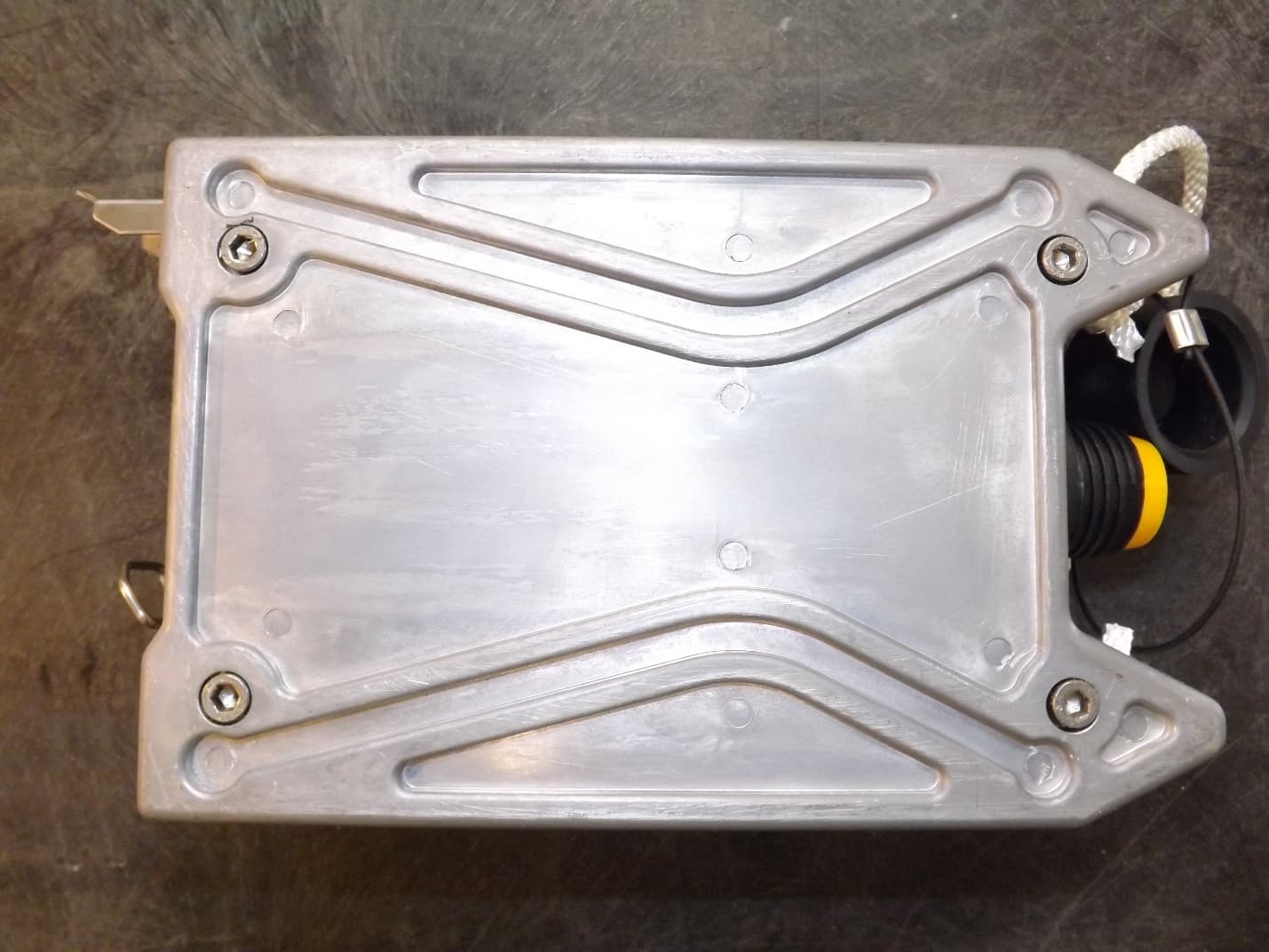
YZO-00106
Jun 24, 2014Wireless remote seismic disturbance sensor
Equipment Class
DSS - Part 15 Spread Spectrum Transmitter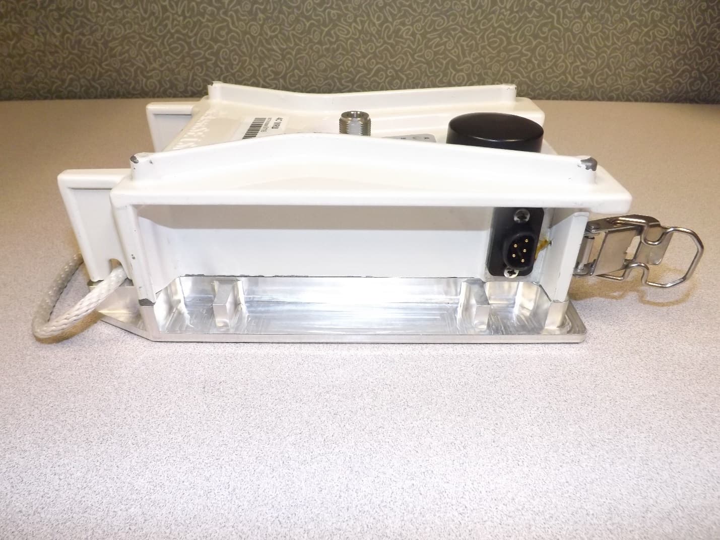
YZO-00104
Dec 30, 2013Wireless Seismic Sensor
Equipment Class
DSS - Part 15 Spread Spectrum Transmitter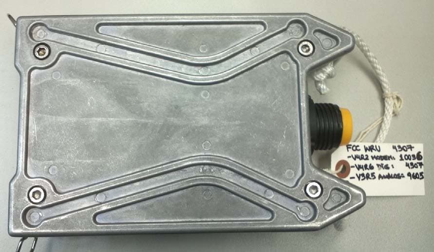
YZO-00103
Aug 06, 2012Wireless Remote Unit
Equipment Class
DSS - Part 15 Spread Spectrum Transmitter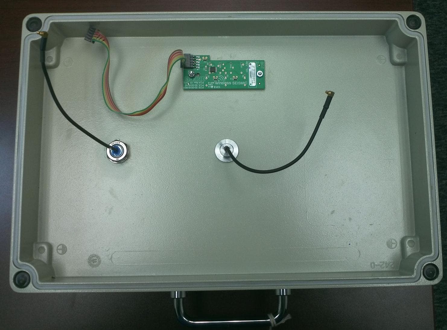
YZO-00600
Jul 26, 2012Line Interface Unit
Equipment Class
DSS - Part 15 Spread Spectrum Transmitter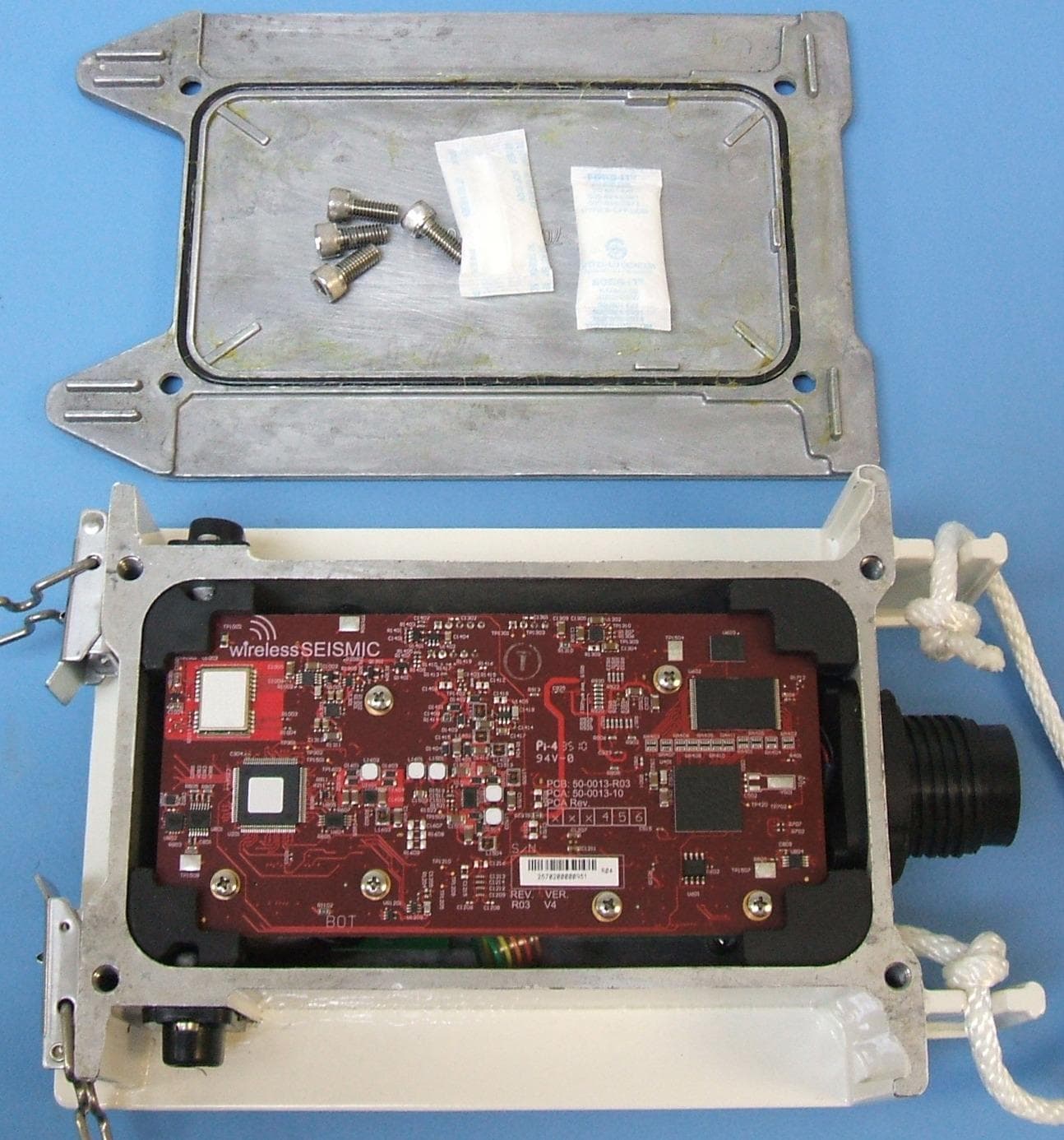
YZO-00102
Apr 08, 2012Wireless Remote Unit
Equipment Class
DSS - Part 15 Spread Spectrum Transmitter