YZO-00401Base Station Unit
Wireless Seismic, Inc.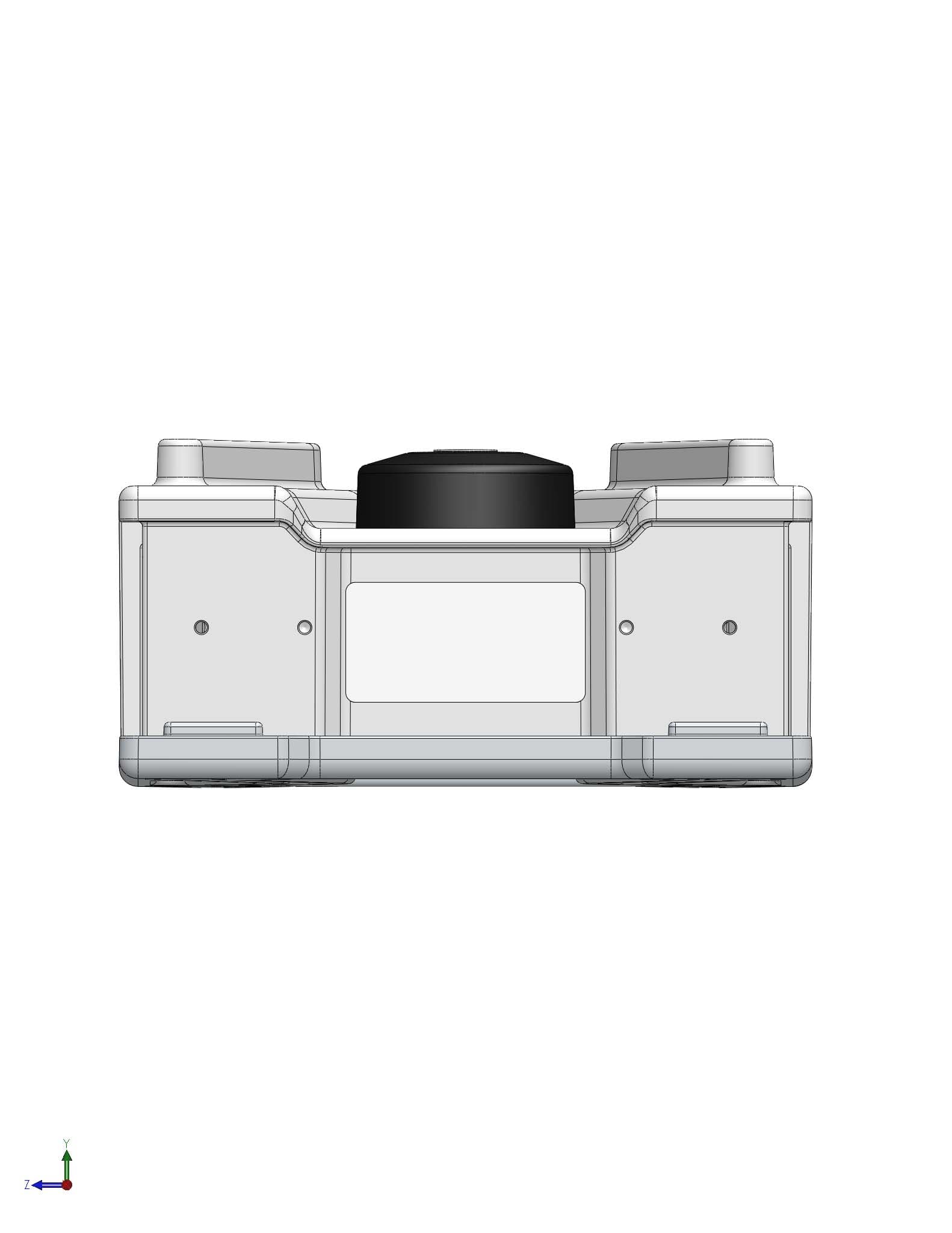
Click to zoom
Application Details
- Equipment Class
- DSS - Part 15 Spread Spectrum Transmitter
- Date of Grant
- Oct 20, 2011
- Application Purpose
- Original Equipment
- Date of Application
- Oct 20, 2011
- Equipment Note
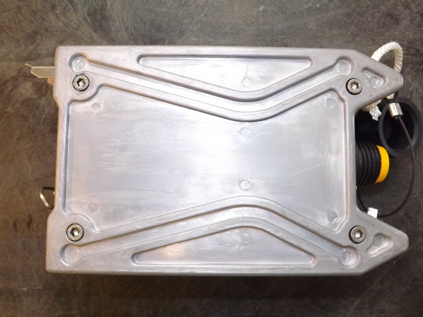
- Base Station Unit
- Frequency Range
- 2403.00000000 - 2478.00000000
- Company
- Wireless Seismic, Inc.
- Country
- United States
Documents & Files
Document Text
Text extracted from the exhibit documents filed with the FCC. Open a document above to read the original.
Users Manual
Draft RT 1000 Deployment Guide September 14, 2011 R03.d Part Number: 90-0004 When Real-time Matters Wireless Seismic, Inc. 361 Centennial Parkway, Suite 230 Louisville, CO 80027 720.242.9916 Draft To order additional copies of this document, send an email to your sales representative requesting the following: Part Number: 90-0004-PDF Part Number: 90-0004-Paper © 2010-2011 Wireless Seismic, Inc. All rights reserved. All other brands, company names, product names, trademarks or service marks referenced in this material are the property of their respective owners, who may or may not be affiliated with, connected to, or sponsored by Wireless Seismic, Inc. Wireless Seismic, Inc.'s trademarks, registered trademarks or trade dress may not be used in connection with any product or service that is not the property of Wireless Seismic, Inc., in any manner that is likely to cause confusion among customers, or in any manner that disparages or discredits Wireless Seismic, Inc. The products and services described in this material may not be available in all regions. Draft RT 1000 v1.33 Deployment Guide R03.d © 2010-2011 Wireless Seismic, Inc. All rights reserved. Table of Contents 1. Overview. . . . . . . . . . . . . . . . . . . . . . . . . . . . . . . . . . . . . . . . . . . . 9 1.1 About this Guide . . . . . . . . . . . . . . . . . . . . . . . . . . . . . . . . . . . . . . . . . . 9 1.2 Who Should Use this Guide. . . . . . . . . . . . . . . . . . . . . . . . . . . . . . . . . . . 9 1.3 Related Documents . . . . . . . . . . . . . . . . . . . . . . . . . . . . . . . . . . . . . . . . 9 1.4 Getting Help . . . . . . . . . . . . . . . . . . . . . . . . . . . . . . . . . . . . . . . . . . . . . 9 2. Layout. . . . . . . . . . . . . . . . . . . . . . . . . . . . . . . . . . . . . . . . . . . . . .11 2.1 Prerequisites. . . . . . . . . . . . . . . . . . . . . . . . . . . . . . . . . . . . . . . . . . . . 11 2.2 Getting Ready. . . . . . . . . . . . . . . . . . . . . . . . . . . . . . . . . . . . . . . . . . . 11 2.3 Preparing the Equipment . . . . . . . . . . . . . . . . . . . . . . . . . . . . . . . . . . . 13 2.4 Setting Up the Central Recording System . . . . . . . . . . . . . . . . . . . . . . . . 13 2.4.1 Setting up the Computer . . . . . . . . . . . . . . . . . . . . . . . . . . . . . . . 13 2.4.2 Connecting to the Source Controller. . . . . . . . . . . . . . . . . . . . . . . . 13 2.5 Laying Out the Equipment . . . . . . . . . . . . . . . . . . . . . . . . . . . . . . . . . . 20 2.5.1 Prerequisites . . . . . . . . . . . . . . . . . . . . . . . . . . . . . . . . . . . . . . . . 21 2.5.2 Assembling the Ground Equipment . . . . . . . . . . . . . . . . . . . . . . . . 21 2.5.3 Placing the WRU in the Field . . . . . . . . . . . . . . . . . . . . . . . . . . . . . 23 2.5.4 Placing the BSU in the Field . . . . . . . . . . . . . . . . . . . . . . . . . . . . . 25 3. Software. . . . . . . . . . . . . . . . . . . . . . . . . . . . . . . . . . . . . . . . . . . .26 3.1 Overview . . . . . . . . . . . . . . . . . . . . . . . . . . . . . . . . . . . . . . . . . . . . . . 26 3.2 Installing the Software. . . . . . . . . . . . . . . . . . . . . . . . . . . . . . . . . . . . . 26 3.3 Upgrading the Software . . . . . . . . . . . . . . . . . . . . . . . . . . . . . . . . . . . . 26 3.4 Upgrading the Firmware. . . . . . . . . . . . . . . . . . . . . . . . . . . . . . . . . . . . 26 4. Backhaul. . . . . . . . . . . . . . . . . . . . . . . . . . . . . . . . . . . . . . . . . . . .27 4.1 Overview . . . . . . . . . . . . . . . . . . . . . . . . . . . . . . . . . . . . . . . . . . . . . . 27 4.2 Backhaul Components . . . . . . . . . . . . . . . . . . . . . . . . . . . . . . . . . . . . . 31 4.2.1 BSU Components. . . . . . . . . . . . . . . . . . . . . . . . . . . . . . . . . . . . . 31 4.2.1.1 BSU . . . . . . . . . . . . . . . . . . . . . . . . . . . . . . . . . . . . . . . . . . 31 4.2.1.2 PoE Switch Unit . . . . . . . . . . . . . . . . . . . . . . . . . . . . . . . . . . 32 4.2.1.3 Battery and Power Supply. . . . . . . . . . . . . . . . . . . . . . . . . . . 33 4.2.1.4 Cables . . . . . . . . . . . . . . . . . . . . . . . . . . . . . . . . . . . . . . . . 34 4.2.2 Antennas . . . . . . . . . . . . . . . . . . . . . . . . . . . . . . . . . . . . . . . . . . 35 4.2.3 Radio Kit Components . . . . . . . . . . . . . . . . . . . . . . . . . . . . . . . . . 35 4.2.3.1 FM1100 Radio . . . . . . . . . . . . . . . . . . . . . . . . . . . . . . . . . . . 37 4.2.3.2 FM3100 Radio . . . . . . . . . . . . . . . . . . . . . . . . . . . . . . . . . . . 37 4.2.4 Mast Kit Components . . . . . . . . . . . . . . . . . . . . . . . . . . . . . . . . . . 38 4.2.4.1 Mast. . . . . . . . . . . . . . . . . . . . . . . . . . . . . . . . . . . . . . . . . . 39 Draft 4RT 1000 v1.3 Deployment GuideR03.d © 2010-2011 Wireless Seismic, Inc. All rights reserved. Table of Contents 4.2.4.2 Base . . . . . . . . . . . . . . . . . . . . . . . . . . . . . . . . . . . . . . . . . .39 4.2.4.3 Bag . . . . . . . . . . . . . . . . . . . . . . . . . . . . . . . . . . . . . . . . . . .42 4.2.4.4 Backpack Kit . . . . . . . . . . . . . . . . . . . . . . . . . . . . . . . . . . . .42 4.3 Configure the Radios . . . . . . . . . . . . . . . . . . . . . . . . . . . . . . . . . . . . . .43 4.3.1 Create a Private Network. . . . . . . . . . . . . . . . . . . . . . . . . . . . . . . .43 4.3.2 Setting NIC Priority. . . . . . . . . . . . . . . . . . . . . . . . . . . . . . . . . . . .51 4.3.3 Configure the Radio . . . . . . . . . . . . . . . . . . . . . . . . . . . . . . . . . . .53 4.3.4 Restore your Network Settings . . . . . . . . . . . . . . . . . . . . . . . . . . . .56 4.4 Setting up the Backhaul Equipment . . . . . . . . . . . . . . . . . . . . . . . . . . . .56 4.5 Installing Two Radios on the Mast . . . . . . . . . . . . . . . . . . . . . . . . . . . . .69 4.6 Removing the Backhaul Equipment. . . . . . . . . . . . . . . . . . . . . . . . . . . . .70 4.7 Use Cases or Example Deplo…
Text truncated - open the document above for the full version.
Users Manual
Draft R03.dRT 1000 v1.3 Deployment Guide61 © 2010-2011 Wireless Seismic, Inc. All rights reserved. Backhaul Setting up the Backhaul Equipment 11Attach a radio to the electronics carrier. 12Uncoil an Ethernet cable, attach one end to a radio unit and the other end to the PoE. Form a service loop (extra cable) by looping the Ethernet cable over the top of the radio unit. If you are installing two radios on the mast, refer to “Installing Two Radios on the Mast” on page 69 for cabling and configuration instructions. 13Ensure that all directional antennas, when raised, are pointed correctly. The radio unit should be facing toward the recording truck. 14Thread guy lines through the guy line collar on the electronics carrier and thread through cleats on the bottom mast tube. Figure 4–34 Hammering Guy Line Stakes Draft 62RT 1000 v1.3 Deployment GuideR03.d © 2010-2011 Wireless Seismic, Inc. All rights reserved. Backhaul Setting up the Backhaul Equipment 15Secure the two lines that angle away from the line of the mast into the cleats at the marks on the rope. The third rope which is in line with the mast will be secured after the mast is raised. Figure 4–35 Guy Line Collar Figure 4–36 Threading Guy Lines Through Cleats Draft R03.dRT 1000 v1.3 Deployment Guide63 © 2010-2011 Wireless Seismic, Inc. All rights reserved. Backhaul Setting up the Backhaul Equipment 16While holding the free guy line, lift / walk the mast to a vertical position and secure the line into the cleat. Figure 4–37 Walking the Mast to Vertical 1 Figure 4–38 Walking the Mast to Vertical 2 Draft 64RT 1000 v1.3 Deployment GuideR03.d © 2010-2011 Wireless Seismic, Inc. All rights reserved. Backhaul Setting up the Backhaul Equipment Figure 4–39 Walking the Mast to Vertical 3 Draft R03.dRT 1000 v1.3 Deployment Guide65 © 2010-2011 Wireless Seismic, Inc. All rights reserved. Backhaul Setting up the Backhaul Equipment 17Adjust all lines to bring the mast to a vertical position. 18Ensure that each line is firmly seated in each cleat, loosely wrap lines around mast and secure at the large cleat on the base. Figure 4–40 Securing the Guy Line to the Cleat Draft 66RT 1000 v1.3 Deployment GuideR03.d © 2010-2011 Wireless Seismic, Inc. All rights reserved. Backhaul Setting up the Backhaul Equipment Figure 4–41 Tightening Guy Lines in Cleats Draft R03.dRT 1000 v1.3 Deployment Guide67 © 2010-2011 Wireless Seismic, Inc. All rights reserved. Backhaul Setting up the Backhaul Equipment Figure 4–42 Wrapping Lines Around the Mast Figure 4–43 Securing Lines to Large Cleat Draft 68RT 1000 v1.3 Deployment GuideR03.d © 2010-2011 Wireless Seismic, Inc. All rights reserved. Backhaul Setting up the Backhaul Equipment 19Check to make sure that the antennas are aimed properly. 20Uncoil an Ethernet cable. Attach one end to the BSU and the other end to the PoE. 21Check Ethernet status lights, if not green or flashing green remove Ethernet cable from the PoE, count to five and re-insert. 22If status does not change to green or flashing green report the condition. Figure 4–44 Backhaul Antenna Erected Draft R03.dRT 1000 v1.3 Deployment Guide69 © 2010-2011 Wireless Seismic, Inc. All rights reserved. Backhaul Installing Two Radios on the Mast 4.5 Installing Two Radios on the Mast When you are installing a remote backhaul, there can be two radios on the mast as shown in the following figure: To install two radios on the mast: 1Prerequisites: ●TBD ●The radios are configured to allow the PoE option (see step 11 on page 56). ●The radios are BOTH configured as mesh POINTS (see step 6 on page 54). 2Attach two radios to the mast. Refer to the deployment instructions for the location at which to aim the radio. One should point towards the recording Figure 4–45 Two-Radio Installation Draft 70RT 1000 v1.3 Deployment GuideR03.d © 2010-2011 Wireless Seismic, Inc. All rights reserved. Backhaul Removing the Backhaul Equipment truck (uplink), and the other should point towards the next remote backhaul location (downlink). 3Connect the two radios with a short Ethernet cable: Radio1/LAN 2 to Radio 2/ LAN 1. 4Connect Radio 1/LAN 1 to the PoE. 4.6 Removing the Backhaul Equipment TBD 4.7 Use Cases or Example Deployments This section shows a few example deployments. Draft R03.dRT 1000 v1.3 Deployment Guide71 © 2010-2011 Wireless Seismic, Inc. All rights reserved. Backhaul Use Cases or Example Deployments Figure 4–46 2D Single Backhaul Draft 72RT 1000 v1.3 Deployment GuideR03.d © 2010-2011 Wireless Seismic, Inc. All rights reserved. Backhaul Use Cases or Example Deployments Figure 4–47 3D Dual Backhaul, Two Root Nodes Draft R03.dRT 1000 v1.3 Deployment Guide73 © 2010-2011 Wireless Seismic, Inc. All rights reserved. Backhaul Use Cases or Example Deployments Figure 4–48 2D Single Backhaul, Star Configuration Draft RT 1000 v1.374 Deployment Guide R03.d © 2010-2011 Wireless Seismic, Inc. All rights reserved. 5 Demobilization 5.1 Overview This chapter describes how to prepare (undeploy) the ground electronics for transport at the end of a project (demobilization). 5.2 Removing the WRU from the Field This section describes the process to ready the WRU for movement to a new physical location or to remove it in preparation for demobilization. To undeploy the WRU: 1Prerequisites: ●The WRU is assembled with battery, geophone, and antenna ●The WRU is in an active, transitional, or ready state 2Pick up the WRU and point the geophone connector end towards the sky as shown in the following figure. All of the LEDs illuminate: 3Place the unit flat in the transportation vehicle as shown in the following figure. The unit shuts down. The LEDs on the top of the unit are off. Figure 5–1 Power Off the Unit Draft R03.dRT 1000 v1.3 Deployment Guide75 © 2010-2011 Wireless Seismic, Inc. All rights reserved. Demobilization Disassemble the WRU 4Optional: Remove batteries, antenna, or geophone as described in “Disassemble the WRU” on page 75. 5.3 Disassemble the WRU This section describes the process to disassemble the W…
Text truncated - open the document above for the full version.
Attestation Statements
Wireless Seismic, Inc. 361 Centennial Parkway, Suite 230 (p) 720.242.9916 Louisville, CO 80027 (f) 720.242.9987 November 17, 2010 PCTEST TCB/CB Division of PCTEST Engineering Lab., Inc. 6660-B Dobbin Road Columbia, MD 21045 To whom it may concern: We, the undersigned, hereby authorize PCTEST Engineering Laboratory Inc., to act on our behalf in all matters relating to applications for equipment authorization, including the signing of all documents relating to these matters. Any and all acts carried out by PCTEST Engineering Laboratory, Inc. on our behalf shall have the same effect as acts of our own. We also hereby certify that no party to this application is subject to a denial of benefits, including FCC benefits, pursuant to Section 5301 of the Anti-Drug Abuse Act of 1988, 21 U.S. C. 862. Sincerely, Shannon Adams VP Finance & Administration
Cover Letter(s)
Wireless Seismic, Inc. 361 Centennial Parkway, Suite 230 (p) 720.242.9916 Louisville, CO 80027 (f) 720.242.9987 August 30, 2011 Federal Communications Commission Authorization and Evaluation Division 7435 Oakland Mills Road, Columbia, MD 21046 RE: Request of Confidentiality for FCC ID: YZO-00401 To Whom It May Concern: Pursuant to Sections 0.457 and 0.459 of the Commission’s Rules (CFR 47), and Section 552 (b) (4) of the Freedom of Information Act, Wireless Seismic, Inc. hereby requests confidentiality and treatment of certain information accompanying this application. The materials contain trade secrets and proprietary information not customarily released to the public. The public disclosure of these matters might be harmful to the Applicant and provide unjustified benefits to its competitors. We are also hereby request Short-Term Confidentiality for 180 days after the grant as outlined in Public Notice DA 04-1705. This provision will give Wireless Seismic, Inc. temporary confidentiality of commercially sensitive information prior to product release. The requested Permanent and Temporary Confidential exhibits are listed as follows: PERMANENT AND SHORT-TERM CONFIDENTIAL LIST Exhibit Description PERMANENT 1 Block Diagram 2 Operational Descriptions 3 Schematics SHORT-TERM CONFIDENTIAL 4 External Photos 5 Internal Photos 6 Test-Setup Photos 7 User’s Manual The Applicant understands that pursuant to Rule 0.457, disclosure of this application and all accompanying documentations, where applicable, will not be made public before the date of the Grant for this application. Wireless Seismic, Inc. Page 2 Sincerely, Shannon Adams VP Finance & Administration
External Photos
BSU FCC Photos
ID Label/Location Info
BSU FCC Label FCC ID YZO-00401 This device complies with part 15 of the FCC Rules. Operation is subject to the following two conditions: (1) This device may not cause harmful interference, and (2) this device must accept any interference received, including interference that may cause undesired operation.
RF Exposure Info
Reviewed by: FCC ID: YZO-00401 MAXIMUM PERMISSIBLE EXPOSURE (MPE) DATA REPORT Quality Manager Test Report S/N: Test Dates: EUT Type: 0Y1105160869R1.YZO September 6, 2011 Base Station Unit Page 1 of 7 © 2011 PCTEST Engineering Laboratory, Inc. REV 3.1MPE 02/09/09 Applicant Name: Date of Testing: Wireless Seismic, Inc. September 6, 2011 13100 Southwest Freeway, Suite 150 Test Site/Location: Sugarland, TX PCTEST Lab, Columbia, MD, USA USA Test Report Serial No.: 0Y1105160869R1.YZO FCC ID: YZO-00401 APPLICANT: Wireless Seismic, Inc. EUT Type: Base Station Unit FCC Rule Part(s): FCC Part 1 (§1.1310) and Part 2 (§2.1091) FCC Classification: FCC Part 15 Frequency Hopping Spread Spectrum Transceiver (DSS) Test Procedure: OET Bulletin 65 The device bearing the FCC Identifier specified above has been shown to comply with the applicable technical standards as indicated in the measurement report and has been tested in accordance with the measurement procedures specified in FCC OET Bulletin 65 (See Test Report). These measurements were performed with no deviation from the standards. Test results reported herein relate only to the item(s) tested. I authorize and attest to the accuracy of data. All measurements reported herein were performed by me or were made under my supervision and are correct to the best of my knowledge and belief. I assume full responsibility for the completeness of these measurements and vouch for the qualifications of all persons taking them. PCTEST certifies that no party to this application has been subject to a denial of Federal benefits that includes FCC benefits pursuant to Section 5301 of the Anti-Drug Abuse Act of 1988, 21 U.S.C. 862. PCTEST ENGINEERING LABORATORY, INC. 6660-B Dobbin Road, Columbia, MD 21045 USA Tel. 410.290.6652 / Fax 410.290.6554 http://www.pctestlab.com RF EXPOSURE EVALUATION (MAXIMUM PERMISSIBLE EXPOSURE) Reviewed by: FCC ID: YZO-00401 MAXIMUM PERMISSIBLE EXPOSURE (MPE) DATA REPORT Quality Manager Test Report S/N: Test Dates: EUT Type: 0Y1105160869R1.YZO September 6, 2011 Base Station Unit Page 2 of 7 © 2011 PCTEST Engineering Laboratory, Inc. REV 3.1MPE 02/09/09 TABLE OF CONTENTS 1.0 RF EXPOSURE EVALUATION – MAXIMUM PERMISSIBLE EXPOSURE (MPE) .........................3 1.1 INTRODUCTION ................................................................................................................................... 3 1.2 EUT DESCRIPTION .............................................................................................................................. 3 1.3 MPE REQUIREMENTS OVERVIEW..................................................................................................... 4 1.4 PROCEDURE........................................................................................................................................ 5 1.5 SUMMARY OF RESULTS ..................................................................................................................... 6 2.0 CONCLUSION..................................................................................................................................7 Reviewed by: FCC ID: YZO-00401 MAXIMUM PERMISSIBLE EXPOSURE (MPE) DATA REPORT Quality Manager Test Report S/N: Test Dates: EUT Type: 0Y1105160869R1.YZO September 6, 2011 Base Station Unit Page 3 of 7 © 2011 PCTEST Engineering Laboratory, Inc. REV 3.1MPE 02/09/09 1.0 RF EXPOSURE EVALUATION – MAXIMUM PERMISSIBLE EXPOSURE (MPE) 1.1 Introduction This document is prepared on behalf of Wireless Seismic, Inc. to show compliance with the RF Exposure requirements as required in §1.1310 of the FCC Rules and Regulations and RSS-102 of Industry Canada. The limit for Maximum Permissible Exposure (MPE), specified in FCC §1.1310, is listed in Table 1-1. According to FCC §1.1310 and RSS-102: the criteria listed in the following table shall be used to evaluate the environmental impact of human exposure to radio-frequency (RF) radiation as specified in §1.1307(b). Frequency Range (MHz) Electric Field Strength (V/m) Magnetic Field Strength (A/m) Power Density (mW/cm 2 ) Average Time (Minutes) (A) Limits For Occupational / Control Exposures (f = frequency) 30-300 61.4 0.163 1.0 6 300-1500 ... ... f/300 6 1500-100,000 ... ... 5.0 6 (B) Limits For General Population / Uncontrolled Exposure (f = frequency) 30-300 27.5 0.073 0.2 30 300-1500 ... ... f/1500 30 1500-100,000 ... ... 1.0 30 Table 1-1. Limits for Maximum Permissible Exposure (MPE) 1.2 EUT Description The Wireless Seismic Base Station Unit FCC ID: YZO-00401 is a frequency hopping spread spectrum transmitter operating in the 2.4GHz frequency range. For this MPE evaluation the device is set to transmit at maximum power in non-hopping mode from the supplied antenna and the RF exposure is evaluated. EUT: FCC ID: YZO-00401 Model: RT 1000 Grantee: Wireless Seismic, Inc. Max. Peak Conducted Power: 17.86dBm Antenna Gain: 9dBi Reviewed by: FCC ID: YZO-00401 MAXIMUM PERMISSIBLE EXPOSURE (MPE) DATA REPORT Quality Manager Test Report S/N: Test Dates: EUT Type: 0Y1105160869R1.YZO September 6, 2011 Base Station Unit Page 4 of 7 © 2011 PCTEST Engineering Laboratory, Inc. REV 3.1MPE 02/09/09 1.3 MPE Requirements Overview Three different categories of transmitters are defined by the FCC in OET Bulletin 65. These categories are fixed installation, mobile, and portable and are defined as follows: o Fixed Installations: fixed location means that the device, including its antenna, is physically secured at a permanent location and is not able to be easily moved to another location. Additionally, distance to humans from the antenna is maintained to at least 2 meters. o Mobile Devices: a mobile device is defined as a transmitting device designed to be used in other than fixed locations and to be generally used in such a way that a separation distance of at least 20 centimeters is normally maintained between the transmitter's radiating structures and the body of the user or nearby persons. Transmitters designed to be…
Text truncated - open the document above for the full version.
Test Report
Reviewed by: FCC ID: YZO-00401 FCC Pt. 15.247 TEST REPORT (CERTIFICATION) Quality Manager Test Report S/N: Test Dates: EUT Type: 0Y11051600870.YZO September 6 - 7, 2011 Base Station Unit Page 1 of 33 © 2011 PCTEST Engineering Laboratory, Inc. REV 1.6BTFI 01/04/11 Applicant Name: Date of Testing: Wireless Seismic, Inc. September 6 - 7, 2011 13100 Southwest Freeway, Suite 150 Test Site/Location: Sugerland, TX PCTEST Lab. Columbia, MD, USA USA Test Report Serial No.: 0Y11051600870.YZO FCC ID: YZO-00401 APPLICANT: Wireless Seismic, Inc. Application Type: Certification Model(s): RT 1000 EUT Type: Base Station Unit Max. RF Output Power: 61.09 mW (17.86dBm) Conducted Frequency Range: 2403 – 2478MHz FCC Classification: FCC Part 15 Spread Spectrum Transmitter (DSS) FCC Rule Part(s): Part 15 Subpart C (15.247) IC Specification(s): RSS-210 Issue 8 This equipment has been shown to be capable of compliance with the applicable technical standards as indicated in the measurement report and was tested in accordance with the measurement procedures specified in ANSI C63.4-2003. Test results reported herein relate only to the item(s) tested. I attest to the accuracy of data. All measurements reported herein were performed by me or were made under my supervision and are correct to the best of my knowledge and belief. I assume full responsibility for the completeness of these measurements and vouch for the qualifications of all persons taking them. Grant Conditions: Power output listed is conducted. PCTEST certifies that no party to this application has been subject to a denial of Federal benefits that includes FCC benefits pursuant to Section 5301 of the Anti-Drug Abuse Act of 1988, 21 U.S.C. 862. PCTEST ENGINEERING LABORATORY, INC. 6660-B Dobbin Road, Columbia, MD 21045 USA Tel. 410.290.6652 / Fax 410.290.6654 http://www.pctestlab.com MEASUREMENT REPORT FCC PART 15.247 / IC RSS-210 Reviewed by: FCC ID: YZO-00401 FCC Pt. 15.247 TEST REPORT (CERTIFICATION) Quality Manager Test Report S/N: Test Dates: EUT Type: 0Y11051600870.YZO September 6 - 7, 2011 Base Station Unit Page 2 of 33 © 2011 PCTEST Engineering Laboratory, Inc. REV 1.6BTFI 01/04/11 TABLE OF CONTENTS FCC PART 15.247 MEASUREMENT REPORT...................................................................................3 1.0 INTRODUCTION......................................................................................................................................4 1.1 SCOPE....................................................................................................................................................... 4 1.2 PCTEST TEST LOCATION........................................................................................................................ 4 2.0 PRODUCT INFORMATION .....................................................................................................................5 2.1 EQUIPMENT DESCRIPTION..................................................................................................................... 5 2.2 EMI SUPPRESSION DEVICE(S)/MODIFICATIONS.................................................................................. 5 2.3 LABELING REQUIREMENTS .................................................................................................................... 5 3.0 DESCRIPTION OF TEST ........................................................................................................................6 3.1 EVALUATION PROCEDURE..................................................................................................................... 6 3.2 RADIATED EMISSIONS ............................................................................................................................ 6 4.0 ANTENNA REQUIREMENTS ..................................................................................................................7 5.0 TEST EQUIPMENT CALIBRATION DATA..............................................................................................8 6.0 TEST RESULTS ......................................................................................................................................9 6.1 SUMMARY ................................................................................................................................................. 9 6.2 20DB BANDWIDTH MEASUREMENT .....................................................................................................10 6.3 OUTPUT POWER MEASUREMENT .......................................................................................................12 6.4 BAND EDGE COMPLIANCE.................................................................................................................... 14 6.5 CARRIER FREQUENCY SEPARATION.................................................................................................. 16 6.6 TIME OF OCCUPANCY ........................................................................................................................... 17 6.7 NUMBER OF HOPPING CHANNELS......................................................................................................20 6.8 CONDUCTED SPURIOUS EMISSIONS .................................................................................................. 21 6.9 RADIATED SPURIOUS EMISSION MEASUREMENTS.......................................................................... 27 6.10 RADIATED RESTRICTED BAND EDGE MEASUREMENTS .................................................................. 31 7.0 CONCLUSION .......................................................................................................................................33 Reviewed by: FCC ID: YZO-00401 FCC Pt. 15.247 TEST REPORT (CERTIFICATION) Quality Manager Test Report S/N: Test Dates: EUT Type: 0Y11051600870.YZO September 6 - 7, 2011 Base Station Unit Page 3 of 33 © 2011 PCTEST Engineering Laboratory, Inc. REV 1.6BTFI 01/04/11 MEASUREMENT REPORT FCC Part 15.2…
Text truncated - open the document above for the full version.
Test Setup Photos
WIRELESS SEISMIC FCC ID: YZO-00401 Model: RT 1000 Test Set-Up Photos EUT Type: Base Station Unit Page 1 of 1 © 2011 PCTEST Engineering Laboratory Inc. TEST SETUP PHOTOGRAPHS
Contact Information
Applicant
Bandele Adepoju(Sr. Engineer, Regulatory Compliance)
Technical Contact
PCTEST Engineering Lab., Inc.Randy Ortanez
[email protected]410-290-6652
6660-B Dobbin Road · Columbia, Maryland · United States
Test Firm
PCTEST Engineering Laboratory, Inc.Randy Ortanez
Technical Specifications
| # | Rule Parts | Frequency Range | Power Output |
|---|---|---|---|
| 1 | 15C | 2.40 GHz - 2.48 GHz | 61.00 mW |
Other Applications from Wireless Seismic, Inc.
YZO-00106
Jun 24, 2014Wireless remote seismic disturbance sensor
Equipment Class
DSS - Part 15 Spread Spectrum Transmitter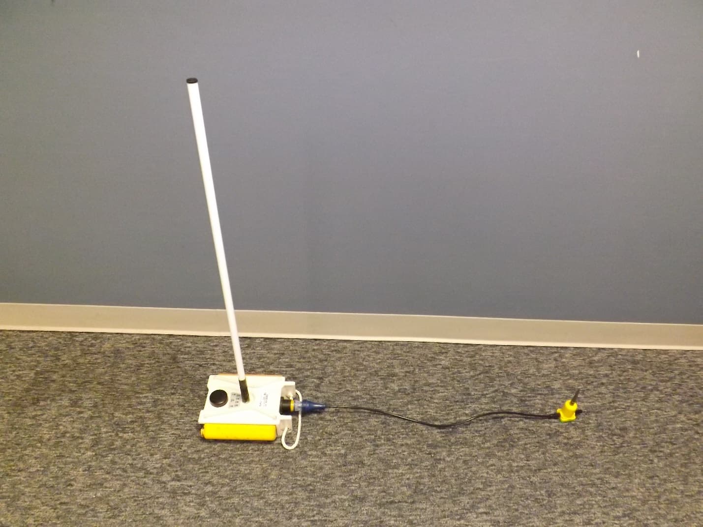
YZO-00105
Apr 29, 2014Wireless Remote Unit
Equipment Class
DSS - Part 15 Spread Spectrum Transmitter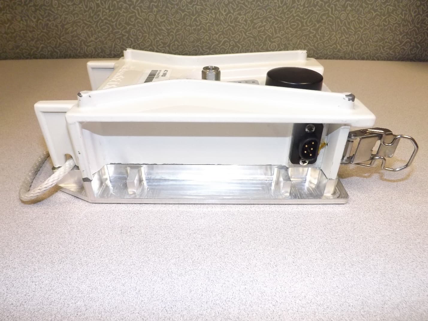
YZO-00104
Dec 30, 2013Wireless Seismic Sensor
Equipment Class
DSS - Part 15 Spread Spectrum Transmitter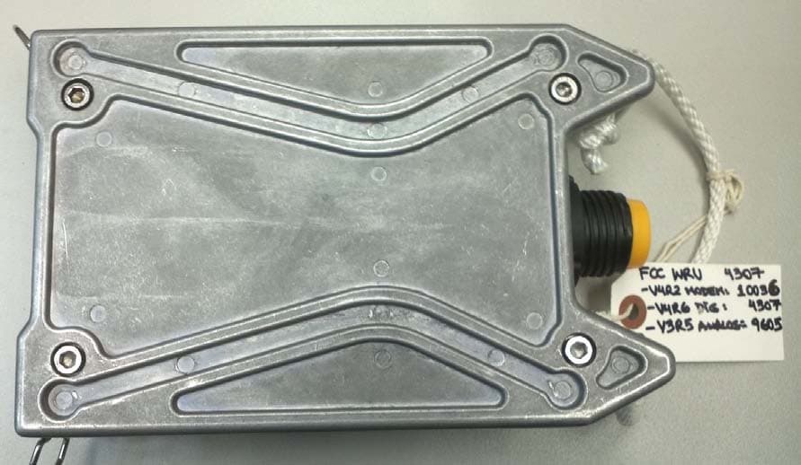
YZO-00103
Aug 06, 2012Wireless Remote Unit
Equipment Class
DSS - Part 15 Spread Spectrum Transmitter
YZO-00600
Jul 26, 2012Line Interface Unit
Equipment Class
DSS - Part 15 Spread Spectrum Transmitter