Z37FM-AFM TRANSMITTER
Besstec Electronics (Zhongshan) Co., Ltd.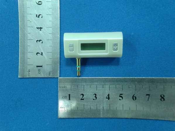
Click to zoom
Application Details
- Equipment Class
- DXX - Part 15 Low Power Communication Device Transmitter
- Date of Grant
- Oct 13, 2011
- Application Purpose
- Original Equipment
- Date of Application
- Oct 13, 2011
- Equipment Note
- FM TRANSMITTER
- Frequency Range
- 88.10000000 - 107.90000000
- Country
- China
Documents & Files
Document Text
Text extracted from the exhibit documents filed with the FCC. Open a document above to read the original.
Users Manual
User Manual Product description FM Transmitter has digital transmitting function, make you enjoy high quality digital music. Beautiful style, various functions, convenient operation, it is the best partner of digital music player. Product Feature Stereo, make you enjore music of high tone quality. Adopt digital PLL technology, can transmit stable radio wave signal. Full range of band design, avoid interference effectively. Can memorize transmitting frequency used last time. Connect all 3.5mm stereo audio output. Maximum effective transmitting distance: 10 meters Blue background light Specification * Working current20±3mA * Frequency scale88.1MHz – 107.9MHzStep 0.1MHz * Transmitting distance3-10 meters Available for * All device which has 3.5mm stereo audio output. Color Black, white, silver Operation Instruction * Connect FM transmitter to 3.5mm audio output hole. *Adjust volume and frequency of FM radio. * Press “+” or “-” to adjust transmitting frequency to match frequency of FM radio. * FM transmitter will memorize the transmitting frequency used last time automatically. LCD DisplayL21mm*W11mm FCC Notice: this device complies with Part 15 of the FCC rules. Operation is subject to the following two conditions: (1) this device may not cause harmful interference, and (2) this device must accept any interference received, including interference that may cause undesired operation. Caution: change or modifications not expressly approved by Kingyou may void the user’s authority to operate this device. FCC ID: Z37FM-A Note: this equipment has been tested and found to comply with the limits for a Class B digital device pursuant to Part 15 of the FCC rules. These limits are designed to provide reasonable protection against harmful interference in a residential installation. This equipment generates, uses, and can radiate radio frequency energy and, if not installed and used in accordance with the instructions, may cause harmful interference to radio communications. However, there is no guarantee that interference will not occur in a particular installation. If this equipment does cause harmful interference to radio or television reception, which can be determined by tuning the equipment off and on, the user is encouraged to try to correct the interference by one or more of the following measures: z reorient or relocate the receiving antenna z increase the separation between the equipment and receiver z connect the equipment into an outlet on a circuit different from that to which the receiver is connected z consult the dealer or an experienced radio/TV technician for help
Block Diagram
Block Diagram ANT 88.1-107.9MHz Oscillation 12 MH Z Battery sound L/R signaL MCU KEY Display Driver part Digital display TX FM Modulate EEPROM LD0=3.3V DC-DC
Cover Letter(s)
Besstec Electronics (Zhongshan) Co., Ltd. Yujing Industrial Park, No. 106, Qihao Road, Torch Development Zone, Zhongshan City, China TEL86-760-88331776 FAX: 86-760-88331706 October 08, 2011 Responses to inquiry for the FM TRANSMITTER (FCC ID: Z37FM-A) 1) How does this device operate? The device is operated as 88.1MHz -107.9MHz FM transmitter and powered by 3.7VDC. It transmit the audio signal from a external audio source such as MP3 player by a FM transmitter tuned on 88.1MHz and the audio signal can be received by a common FM Broadcasting Radio which is tuned to the same transmitted frequency of the FM transmitter and regenerate the transmitted signal through the FM Broadcasting Radio. 2) Provide information on the device and its antenna. Antenna is formed by a short copper wire soldered on the PCB. (please see the attached picture) 3) How is it installed? It is very easy to install. It can connect to all device which has 3.5mm stereo audio output. 4) What test procedure was used? ANCI C63.4:2003 Antenna Besstec Electronics (Zhongshan) Co., Ltd. Yujing Industrial Park, No. 106, Qihao Road, Torch Development Zone, Zhongshan City, China TEL86-760-88331776 FAX: 86-760-88331706 5) If tested in a car, how was it configured? Not tested in a car, it was tested in a semi-anechoic chamber. 6) Was the tuning range properly verified? The test lab should indicate in the report that the tuning controls were manually adjusted to verify maximum tuning range. 88.1-107.9MHZ. 7) Was the bandwidth properly tested with maximum audio input? The test lab should describe the audio input signal (use a typical audio file from a typical device) - DO NOT use 1kHz tone from signal generator as specified under ETSI EN 301 357-1) The maximum output Level of the typical device, ipod player is used. Connect EUT use iPod playing typical audio signal (‘Highway Blues’ from sample music of windows XP) with maximum audio level 8) Does the device operate in a vehicle? Please state that this was verified. It was not test in a vehicle. 9) Provide the test report Provided.
ID Label/Location Info
FCC Certification Label FCC ID: Z37FM-A This device complies with Part 15 of the FCC Rules.Operation is subject to the following two conditions: 1. This device may not cause harmful interference, and 2. This device must accept any interference received, including interference that may cause undesired operation. Label Location on EUT EUT View/ FCC ID Label Location
Internal Photos
Antenna
Operational Description
Operation Description Most of the functions are controlled by MCU chip. For example, digital tube display, button inspection, RF setup and control and etc. Power management chip provides host with 3.3V power. EEPROM memory chip stores the previous frequency when the power is disconnected. Once the host is powered, Mcu will first read the previous frequency stored in EEPROM memory chip, and then MCU will set up stereo FM modulation PLL chip, After the above-mentioned setup, Mcu will mobile scan digital tube and display current frequency. When detecting any operation of +/- button, Mcu will update PLL chip parameter and display current frequency.
Schematics
1 2 3 4 56 ABCD 6 5 4 3 2 1 D CBA Title Number Revision Size B Date: 24-Sep-2011 Sheet of File: F:\FM\SHE\FM.DDB Drawn By: 1098 7123465 11121314 U?SN8P2501B 5 123 4 U?4120 123456789101112 LCD?LCD 12346789 101112131415161718192021222324 5 484746454443424140393837363534333231302928272625 U?HT1621 1 D? AN 1 2 3 ER 1 2 D? 8765 1234 U?24C02 12 BGB 12 JACK 21 L? 21 L? 5 123 4 U?S910 12 C? 12 C? 10 987 1234 6 5 U?QN8027 2 1 R? 21 R? 21 R? 21 R? 21 R? 3 12 Q?A1AM 3 12 Q?A J8 3 1 2 Q?AM6 3 12 Q?A1AM 12 C? 1 2 C? 12 C? 12 C? 1 2 C? 1 2 C?C5 1 2 C?C5 1 2 C? 12 C? 12 C? 12 C? 2 1 R? 21 R? 21 R? 21 R? 2 1 R? 2 1 R? 2 1 R? 2 1 R? 2 1 R? 2 1 R? 21 R? 2 1 R? 21 R? 21 R? 2 1 R? 2 1 R? 2 1 R? 1 2 S?S1 12 S?S1 2 1 L? 1 2 Y? 12 B?BAT
Test Report
FCC PART 15.239 EMI MEASUREMENT AND TEST REPORT For Besstec Electronics (Zhongshan) Co., Ltd. Yujing Industrial Park, No. 106, Qihao Road, Torch Development Zone, Zhongshan City, China FCC ID: Z37FM-A October 8, 2011 This Report Concerns: Original Report Equipment Type: FM TRANSMITTER Test Engineer: Eric Li Report No.: BSTDG11090099Y-1ER-3 Receive EUT Date/Test Date: September 25, 2011/ September 26-30, 2011 Reviewed By: Christina Prepared By: Shenzhen BST Technology Co.,Ltd. 3F,Weames Technology Building, No. 10 Kefa Road, Science Park, Nanshan District,Shenzhen,Guangdong,China Tel: 0755-267477513 Fax: 0755-267477513 ext.826 Note: The test report is specially limited to the above company and this particular sample only. It may not be duplicated without prior written consent of Shenzhen BST Technology Co.,Ltd. This report must not be used by the client to claim product certification,approval,or endorsement by NVLAP, NIST or any agency of the US Government. Besstec Electronics (Zhongshan) Co., Ltd. FCC ID: Z37FM-A FCC ID REPORT: BSTDG11090099Y-1ER-3 Page 2/20 TABLE OF CONTENTS 1. GENERAL INFORMATION ....................................................................................................3 1.1. Report information ............................................................................................................3 1.2. Measurement Uncertainty .................................................................................................3 2. PRODUCT DESCRIPTION ......................................................................................................4 2.1. EUT Description ...............................................................................................................4 2.2. Block Diagram of EUT Configuration..............................................................................4 2.3. Support Equipment List ....................................................................................................4 2.4. Test Conditions .................................................................................................................4 3. FCC ID LABEL...........................................................................................................................5 4. TEST RESULTS SUMMARY ...................................................................................................6 Modifications ................................................................................................................................6 5. TEST EQUIPMENT USED .......................................................................................................7 6. ANTENNA REQUIREMENT ...................................................................................................8 6.1. STANDARD APPLICABLE............................................................................................8 6.2. ANTENNA CONNECTED CONSTRUCTION ..............................................................8 6.3. Result ................................................................................................................................8 7. CONDUCTED POWER LINE TEST .......................................................................................9 7.1. Test Equipment .................................................................................................................9 7.2. Test Procedure ..................................................................................................................9 7.3. Test Setup..........................................................................................................................9 7.4. Conducted Power line Emission Limits............................................................................9 7.5. Conducted Power Line Test Result.................................................................................10 8. FUNDAMENTAL RADIATED EMISSION FOR FCC PART 15 SECTION 15.239(B) ..11 8.1. Test Equipment ...............................................................................................................11 8.2. Test Procedure ................................................................................................................11 8.3. Radiated Test Setup ........................................................................................................12 8.4. Radiated Emission Limit.................................................................................................12 8.5. Radiated Emission Test Result .......................................................................................13 9. HARMONICS AND SPURIOUS RADIATED EMISSION FOR FCC PART 15 SECTION 15.239(C) ....................................................................................................................................14 9.1. Test Equipment ...............................................................................................................14 9.2. Test Procedure ................................................................................................................14 9.3. Radiated Test Setup ........................................................................................................15 9.4. Radiated Emission Limit.................................................................................................15 9.5. Radiated Emission Test Result .......................................................................................16 10. OCCUPIED BANDWIDTH FOR FCC PART 15 SECTION 15.239(A) .............................17 10.1. Test Equipment ...............................................................................................................17 10.2. Test Procedure ................................................................................................................17 10.3. Band Edge FCC 15.249(d) Limit ....................................................................................17 10.4. Ban…
Text truncated - open the document above for the full version.
Test Setup Photos
Radiated emissions test
Contact Information
Applicant
Minghua Zhan(QC Manager)
Test Firm
SinTek Laboratory Co., Ltd.Eric Lin
Technical Specifications
| # | Rule Parts | Frequency Range | Power Output |
|---|---|---|---|
| 1 | 15C | 88.1 MHz - 107.9 MHz | - |
Other Applications from Besstec Electronics (Zhongshan) Co., Ltd.

Z371500061
Jan 26, 2015Wireless FM Transmitter
Equipment Class
DXX - Part 15 Low Power Communication Device TransmitterZ37RS-05
Nov 06, 2014Bluetooth Selfie Stick
Equipment Class
DSS - Part 15 Spread Spectrum TransmitterZ37S-01
Jul 28, 2014Bluetooth Headset
Equipment Class
DTS - Digital Transmission System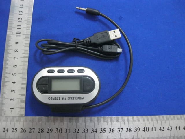
Z37FM-B
May 25, 2013FM Transmitter
Equipment Class
DXX - Part 15 Low Power Communication Device Transmitter