Z52-NASRP01Z1URepeater
SHENZHEN NEO ELECTRONICS CO.,LTD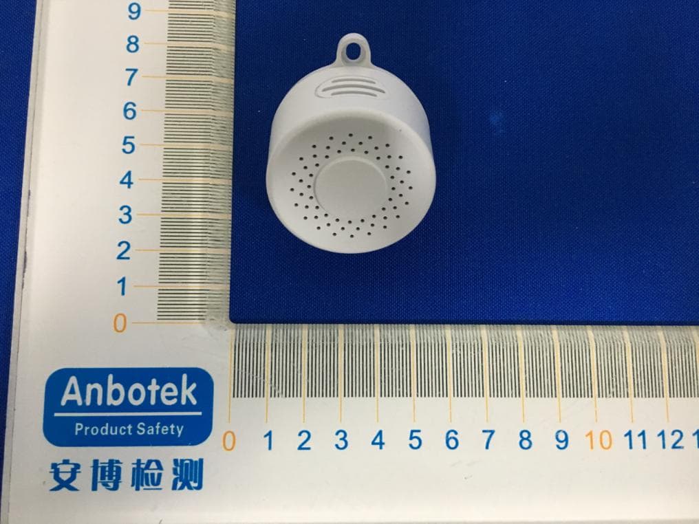
Click to zoom
Application Details
- Equipment Class
- DXX - Part 15 Low Power Communication Device Transmitter
- Date of Grant
- Jan 18, 2020
- Application Purpose
- Original Equipment
- Date of Application
- Jan 18, 2020
- Equipment Note
- Repeater
- Frequency Range
- 916.00000000 - 916.00000000
- Country
- China
Documents & Files
Document Text
Text extracted from the exhibit documents filed with the FCC. Open a document above to read the original.
Users Manual
RepeaterUserManual Model : NAS-RP01Z1U (S2Version) Thankyouforyoursupport Pleasereadtheinstructionmanualcarefullybeforeoperating Pleasekeeptheinstructionmanualforfurtherreference ThisproductcanbeincludedandoperatedinanyZ-Wave™networkwithotherZ-Wave™certified devicesfromothermanufacturersand/orotherapplications.Allnon-batteryoperatednodeswithin thenetworkwillactasrepeatersregardlessofvendortoincreasereliabilityofthenetwork. Operationconfiguration Specifications PowerSupply85–240VAC,50/60Hz PowerConsumptionUpto0.8W OperationalTemperature 0-40°C Communicationfrequency 908.40MHz,916.00MHz(US) Range Upto80mindoors(dependingonthebuildingstructure) Upto100moutdoors. Detecttemperaturerange -20~80°C CompatiblewithanyZ-Wavemaincontroller. Theusedistanceoftheequipmentcanbeincreasedbyrepeater,andthedistancecanbe increasedbyupto100m. Withatemperatureprobe,thetemperaturecanbedetected,thedetectionrangeis-20~80°C Useofflameretardantmaterials Z-Wave™NetworkInclusion/Exclusion/Reset Thereisonebuttononthesideofthedevice,itcanbeexecutedinclusion,exclusionandresetfromZ- Wave™network. Add¹ 1、Powerupthedevice. 2、SetZ-Wave™Controllerintoinclusion mode 3、Pressandholdthebuttonfor5suntil greenledlightsison,thenreleasethe buttonbeforegreenledturnoff. Blueledwillblinkwith 1sintervaluntil inclusionsuccessful. Remove 1、Powerupthedevice. 2、SetZ-Wave™Controllerintoexclusion mode 3、Pressandholdthebuttonfor5suntil Greenledlightsison,thenreleasethe buttonbeforegreenledturnoff. Blueledwillblinkwith 1sintervaluntil exclusionsuccessful. FactoryReset² 1、Powerupthedevice. 2、Pressandholdthebuttonfor10suntilRed ledlightsison,thenreleasethe buttonbeforeredledturnoff. ProductTest Mode 1、Pressandholdthebutton. 2、Poweronthedevice,devicewillenter factoryproducttestmode SendNIF³ Pressandholdthebuttonfor5suntilGreen ledlightsison,thenreleasethe buttonbeforegreenledturnoff. Notice1:Whendeviceentersintoinclusionmode,thedeviceallfunctionalitywillbeuseless.The inclusionmodewillbetimeoutafter30s,usercanpressandholdthebuttonfor5stoterminate inclusionmode. Notice2:FactoryResetwillclearthedeviceallZ-Wave™Networkdata(includehomeid,nodeid, etc...)savedinmemory,andrestoreallconfigurationparameterstofactorydefault.Pleaseusethis procedureonlywhenthenetworkprimarycontrollerismissingorotherwiseinoperable. Notice3:NIF–NodeInformation Association Thedevicesupports5associationgroups,andeachgroupsupportsmax5associatednodes. Group1,Lifeline–Allnodeswhichassociatedingroup1(lifelinegroup)willreceivethemessagesthat sendbydevicethroughlifeline. Group2,allnodeswhichassociatedingroup2willbecontrolledbydevicethroughBASIC_SET command.Whenambienttemperaturevalueislessthanthesettingvaluein“Configuration:No.6”, devicewilltriggeralowtemperatureAlarmandsendaBASIC_SET=0xFFtothenodesthatassociated ingroup2.AndBASIC_SET=0x00willbesentwhentemperaturevalueislargethanthesettingvalue in“Configuration:No.6”. Group3,allnodeswhichassociatedingroup3willbecontrolledbydevicethroughBASIC_SET command.Whenambienttemperaturevalueislessthanthesettingvaluein“Configuration:No.7”, devicewilltriggeralowtemperatureAlarmandsendaBASIC_SET=0xFFtothenodesthatassociated ingroup3.AndBASIC_SET=0x00willbesentwhentemperaturevalueislargethanthesettingvalue in“Configuration:No.7”. Group4,allnodeswhichassociatedingroup4willbecontrolledbydevicethroughBASIC_SET command.Whenambienthumidityvalueislessthanthesettingvaluein“Configuration:No.8”, devicewilltriggeralowhumidityAlarmandsendaBASIC_SET=0xFFtothenodesthatassociatedin group4.AndBASIC_SET=0x00willbesentwhenhumidityvalueislargethanthesettingvaluein “Configuration:No.8”. Group5,allnodeswhichassociatedingroup5willbecontrolledbydevicethroughBASIC_SET command.Whenambienthumidityvalueislessthanthesettingvaluein“Configuration:No.9”, devicewilltriggeralowhumidityalarmandsendaBASIC_SET=0xFFtothenodesthatassociatedin group5.AndBASIC_SET=0x00willbesentwhenhumidityvalueislargethanthesettingvaluein “Configuration:No.9”. TheCommandClasssupportedbyeachassociationgroupisshowninthetablebelow: GroupCommandClassCommand 1(Lifeline)COMMAND_CLASS_SENSOR_MULTILEVEL COMMAND_CLASS_INDICATOR COMMAND_CLASS_DEVICE_RESET_LOCALLY SENSOR_MULTILEVEL_REPORT INDICATOR_REPORT DEVICE_RESET_LOCALLY_NOTIFICATION 2(Control)COMMAND_CLASS_BASICBASIC_SET 3(Control)COMMAND_CLASS_BASICBASIC_SET 4(Control)COMMAND_CLASS_BASICBASIC_SET 5(Control)COMMAND_CLASS_BASICBASIC_SET DeviceFunctionalityandZ-Wave™MessageReport Thisdevicehastwomainfunctions:repeaterandambienttemperatureandhumiditymeasured. Repeater Thisdeviceisaz-waverepeaterdevice.Inthez-wavenetwork,itcanbeasaroutertoextendthe communicationdistance. Temperatureandhumiditymonitor Thedevicehaveembedsatemperatureandhumiditysensortomonitorambienttemperatureand humidityvariationandreporttoz-wavehubs. CommandClassSensorMultilevel TemperatureSensor Whentheambienttemperaturedifferentialover1.0°Cor1.0degreeF(indefault,anddecidesby “ConfigurationNo.4”),thedevicewillunsolicitedtosenda“SENSOR_MULTILEVEL_REPORT”to nodeswhichassociatedinlifeline. CommandClassCOMMAND_CLASS_SENSOR_MULTILEVEL CommandSENSOR_MULTILEVEL_REPORT TypeAirTemperature Scale0.1DegreeCelsius/Fahrenheit(US) HumiditySensor Whentherelativehumiditydifferentialover1.0%RH(indefault,anddecidesby“ConfigurationNo. 5”),thedevicewillunsolicitedtosenda“SENSOR_MULTILEVEL_REPORT”tonodeswhich associatedinlifeline. CommandClassCOMMAND_CLASS_SENSOR_MULTILEVEL CommandSENSOR_MULTILEVEL_REPORT TypeHumidity Scale0.1%RH CommandClassConfiguration ThedevicesupportsthecontrollertoconfigureparametersofthedevicethroughConfiguration CommandClass,andthedevicehas11parametersavailableforuserstosetaccordingtotheir differentneeds: SensorRunningIndicatorEnable 1)Whensensorenterstomeasuremode,thissettingdecidestheLedindicatedornot.‘0’–Noledblinks. ‘1’–ledblinkswithred. ParameterNumberSize(Byte)AvailableSettingsDefaultvalue 110,11 2)OTALedDisable WhenOTAisrunning,thissettingdecidestheLedblinkingornot. ‘0’–NoLedblinks. ‘1’–Ledblinkswithyellow. ParameterNumberSize(Byte)AvailableSettingsDefaultvalue 210,11 3)Temperat…
Text truncated - open the document above for the full version.
External Photos
FCC ID: Z52-NASRP01Z1U
ID Label/Location Info
Label Location On EUT Label Product Name: Repeater Model No.: NAS-RP01Z1U FCC ID: Z52-NASRP01Z1U
Internal Photos
FCC ID: Z52-NASRP01Z1U
Operational Description
version01 SHENZHEN NEO ELECTRONICS CO.,LTD Declaration concerning Antenna Specification It is hereby declared that the product Model No.: NAS-RP01Z1U FCCID:Z52-NASRP01Z1U fulfills the requirement in FCC test relating to the antenna type. The device specified above confirms to the FCC recommendations for internalantenna type(s) described below: Model No. of antenna: NAS-RP01Z1U Type of antenna: Sprin gantenna Gain of the antenna: 0 dBi Frequency range: 908.4 MHz & 916MHz The mounting of the antenna is fixed to the radio module and no other antenna should be used. Company name: SHENZHEN NEO ELECTRONICS CO.,LTD Address: East6/F Building 2,Laobing industry,Baoan District,Shenzhen,518000,China City:Baoan District ZIP / Postal code: N.A. Country:China Place:Shenzhen Date: 2020-01-17 Signature:
RF Exposure Info
RFEXPOSUREEVALUATION AccordingtoFCC1.1310:Thecriterialistedinthefollowingtableshallbeusedto evaluatetheenvironmentimpactofhumanexposuretoradiofrequency(RF)Radiation asspecifiedin§1.1307(b) FCCID:Z52-NASRP01Z1U EUTSpecification EUTRepeater Frequencyband(Operating)WLAN:2.412GHz~2.462GHz WLAN:5.18GHz~5.32GHz/5.50GHz~5.70GHz WLAN:5.745GHz~5825GHz Others:908.4MHz&916MHz DevicecategoryPortable(<20cmseparation) Mobile(>20cmseparation) Others ExposureclassificationOccupational/Controlledexposure(S=5mW/cm2) GeneralPopulation/Uncontrolledexposure(S=1mW/cm2) AntennadiversitySingleantenna MultipleantennasTx diversity Rxdiversity Tx/Rxdiversity Max.outputpower 908.4MHz:-35.6dBm(0.00028mW)&916MHz:-34.78dBm(0.00033mW) Antennagain(Max)0dBi EvaluationappliedMPEEvaluation SAREvaluation LimitsforMaximumPermissibleExposure(MPE) Frequency Range(MHz) ElectricField Strength(V/m) MagneticField Strength(A/m) Power Density(mW/cm 2 ) Average Time (A)LimitsforOccupational/ControlExposures 300-1500----F/3006 1500-100000----56 (B)LimitsforGeneralPopulation/UncontrolExposures 300-1500----F/15006 1500-100000----130 Friistransmissionformula:Pd=(Pout*G)\(4*pi*R2) Where Pd=PowerdensityinmW/cm 2 Pout=outputpowertoantennainMw G=gainofantennainlinearscale Pi=3.1416 R=distancebetweenobservationpointandcenteroftheradiatorincm PdthelimitofMPE,1mW/cm2.Ifweknowthemaximumgainoftheantennaand totalpowerinputtotheantenna,throughthecalculation,wewillknowthedistance wheretheMPElimitisreached. MeasurementResult 908.4MHz 13.56MHz MPECalculationMethod P=PeakRFoutputpower(W) G=EUTAntennanumericgain(numeric) R=Separationdistancebetweenradiatorandhumanbody (m)=0.2mTheformulacanbechangedto Pd=Pout*G/(4*Pi*R2) EIRP=E-104.8+20logD=59.66-104.8+20log3=-35.60dBm TheSARmeasurementisnotnecessary. Channel Frequency (MHz) Antenna Gain (dBi) MaxOutput power (dBuV/m) MaxOutput power (dBm) Power densityat 20cm(mW/ cm2) Power density Limits (mW/cm2) 908.4 059.66 -35.605.3e-051 Channel Frequency (MHz) Antenna Gain (dBi) MaxOutput power (dBuV/m) MaxOutput power (dBm) Power densityat 20cm(mW/ cm2) Power density Limits (mW/cm2) 916 060.48 -34.786.4e-051
Test Report
Report No.: SZAWW191017006-01FCC ID: Z52-NASRP01Z1UPage 1 of 37 Code:AB-RF-05-a FCC TEST REPORT Client Name: SHENZHEN NEO ELECTRONICS CO.,LTD Address: East6/F Building 2,Laobing industry,Baoan District,Shenzhen,518000,China Product Name: Repeater Date: Jan. 16, 2020 Shenzhen Anbotek Compliance Laboratory Limited Report No.: SZAWW191017006-01FCC ID: Z52-NASRP01Z1UPage 2 of 37 Code:AB-RF-05-a Contents 1. General Information ............................................................................................................................................... 4 1.1. Client Information ....................................................................................................................................... 4 1.2. Description of Device (EUT) ..................................................................................................................... 4 1.3. Auxiliary Equipment Used During Test ................................................................................................... 5 1.4. Description of Test Modes ........................................................................................................................ 5 1.5. List of Channels .......................................................................................................................................... 5 1.6. Description of Test Setup .......................................................................................................................... 6 1.7. Test Equipment List .................................................................................................................................... 7 1.8. Measurement Uncertainty ......................................................................................................................... 8 1.9. Description of Test Facility ........................................................................................................................ 8 2. Summary of Test Results ..................................................................................................................................... 9 3. Conducted Emission Test ................................................................................................................................... 10 3.1. Test Standard and Limit .......................................................................................................................... 10 3.2. Test Setup .................................................................................................................................................. 10 3.3. Test Procedure .......................................................................................................................................... 10 3.4. Test Data .................................................................................................................................................... 11 4. Radiated Emission and Band Edge .................................................................................................................. 16 4.1. Test Standard and Limit .......................................................................................................................... 16 4.2. Test Setup .................................................................................................................................................. 17 4.3. Test Procedure .......................................................................................................................................... 18 4.4. Test Data .................................................................................................................................................... 19 5. 20dB Bandwidth Test .......................................................................................................................................... 26 5.1. Test Standard and Limit .......................................................................................................................... 26 5.2. Test Setup .................................................................................................................................................. 26 5.3. Test Procedure .......................................................................................................................................... 26 5.4. Test Data .................................................................................................................................................... 26 6. Antenna Requirement ......................................................................................................................................... 28 6.1. Test Standard and Requirement ............................................................................................................ 28 6.2. Antenna Connected Construction .......................................................................................................... 28 APPENDIX I -- TEST SETUP PHOTOGRAPH ................................................................................................... 29 APPENDIX II -- EXTERNAL PHOTOGRAPH ..................................................................................................... 31 APPENDIX III -- INTERNAL PHOTOGRAPH ..................................................................................................... 34 Report No.: SZAWW191017006-01FCC ID: Z52-NASRP01Z1UPage 3 of 37 Code:AB-RF-05-a TEST REPORT Applicant: SHENZHEN NEO ELECTRONICS CO.,LTD Manufacturer: SHENZHEN NEO ELECTRONICS CO.,LTD Product Name: Repeater Model No.: NAS-RP01Z1U Trade Mark: NEO Rating(s): Input: AC 85-240V, 50/60Hz Test Standard(s) : FCC Part15 Subpart C, Paragraph 15.249 Test Method(s): ANSI C63.10: 2013 The device described above is tested by Shenzhen Anbotek Compliance Laboratory Limited to determine the maximum emission levels emanating from the device and the severe levels of th…
Text truncated - open the document above for the full version.
Test Setup Photos
FCC ID: Z52-NASRP01Z1U Photo of Conducted Emission Test Photo of Radiation Emission Test
Contact Information
Applicant
Wu Binnv(Manager)
Test Firm
Shenzhen Anbotek Compliance Laboratory LimitedJeff Zhu
Technical Specifications
| # | Rule Parts | Frequency Range | Power Output |
|---|---|---|---|
| 2 | 15C | 916 MHz - 916 MHz | - |
Other Applications from SHENZHEN NEO ELECTRONICS CO.,LTD

Z52NAS-ZW05B
Jul 21, 2024Wired Gateway
Equipment Class
DTS - Digital Transmission System
Z52NAS-WV03B2
Sep 26, 2023Water Valve
Equipment Class
DTS - Digital Transmission System
Z52NAS-WV02W9
Dec 01, 2022Water Valve
Equipment Class
DTS - Digital Transmission System
Z52NAS-WR12Z1U
Aug 11, 2021Smart plug
Equipment Class
DXX - Part 15 Low Power Communication Device Transmitter
Z52NAS-PD07Z1U
Aug 10, 2021Motion sensor
Equipment Class
DXX - Part 15 Low Power Communication Device Transmitter