Z52NAS-DS07Z1UDoor Sensor
SHENZHEN NEO ELECTRONICS CO.,LTD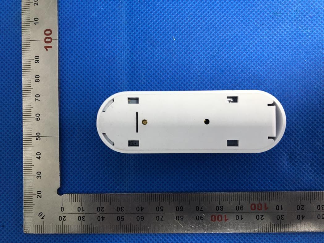
Click to zoom
Application Details
- Equipment Class
- DXX - Part 15 Low Power Communication Device Transmitter
- Date of Grant
- May 31, 2020
- Application Purpose
- Original Equipment
- Date of Application
- May 31, 2020
- Equipment Note
- Door Sensor
- Frequency Range
- 916.00000000 - 916.00000000
- Country
- China
Documents & Files
Document Text
Text extracted from the exhibit documents filed with the FCC. Open a document above to read the original.
Users Manual
Instruction Manual Door Sensor Thank you for your support ⚫ Please read the instruction manual carefully before operating ⚫ Please keep the instruction manual for future reference NOTE: This equipment has been tested and found to comply with the limits for a Class B digital device, pursuant to part 15 of the FCC Rules. These limits are designed to provide reasonable protection against harmful interference in a residential installation. This equipment generates uses and can radiate radio frequency energy and, if not installed and used in accordance with the instructions, may cause harmful interference to radio communications. However, there is no guarantee that interference will not occur in a particular installation. If this equipment does cause harmful interference to radio or television reception, which can be determined by turning the equipment off and on, the user is encouraged to try to correct the interference by one or more of the following measures: - Reorient or relocate the receiving antenna. - Increase the separation between the equipment and receiver. -Connect the equipment into an outlet on a circuit different from that to which the receiver is connected. -Consult the dealer or an experienced radio/TV technician for help Changes or modifications not expressly approved by the party responsible for compliance could void the user's authority to operate the equipment. This device complies with Part 15 of the FCC Rules. Operation is subject to the following two conditions: (1) this device may not cause harmful interference, and (2) this device must accept any interference received, including interference that may cause undesired operation. The Water Leakage Detector is a Z-Wave™ enabled device and is fully compatible with any Z-Wave™ enabled network. Z-Wave™ enabled devices displaying the Z-Wave™ logo can also be used with it regardless of the manufacturer, and ours can also be used in other manufacturer’s Z-Wave™ enable networks. This product can be included and operated in any Z-Wave™ network with other Z-Wave™ certified devices from other manufacturers and/or other applications. All non-battery operated nodes within the network will act as repeaters regardless of vendor to increase reliability of the network. Product Introduction Door sensor is an intelligent security equipment that can transmit the Z-wave network which has particular frequency. In the Z-wave network communications, door sensor can be connected to any Z-wave main controller. The door sensor can send messages to the Z-wave main controller, and realize association with other devices through the Z-wave main controller. Different countries or areas, the radio frequency is different. In the communication with the Z-wave main controller, the door sensor can send messages to the Z-wave main controller, but it can not receive messages from the Z-wave main controller. When alarm is triggered, the door sensor sends messages to the Z-wave main controller, the Z-wave main controller will displays the current status of door sensor, so the door sensor can associate with other devices. Door sensor is battery powered, is small and can be installed on the window or door easily. When the door or window is open, the door sensor is triggered and linkage alarm realized. Specifications Power Supply CR123 × 1 Standby Current Work Current(RF Tx) Up to 15mA Operational Temperature 0 - 70°C Communication frequency 868.40MHz, 869.85MHz (EU) 908.40MHz, 916.00MHz(US) Range Up to 45m indoors (depending on the building structure), and 80m for outdoor open fields. Up to 60m outdoors. Technical Information ⚫ Install on the door or window. ⚫ Battery powered. ⚫ Easily install with screws or sticker. ⚫ Associate with other devices through the gateway. ⚫ Compatible with any Z-wave network. ⚫ It can be powered by USB Product Configuration Product List ⚫ Door sensor main body 1pc ⚫ Door sensor deputy body 1pc ⚫ Battery 2pcs ⚫ Screw 4pcs ⚫ Screw stopper 4pcs ⚫ Sticker 2pcs ⚫ Instruction manual 1pc Door sensor deputy body Sticker Screw stopper Screw The code button Battery Disassemble button 复位 键 USB接 口 指示 灯 tamper alarm indicator light USB interface Z-Wave™ Network Inclusion/Exclusion/Reset Remove the sensor casing, there is one button on the top side of PCB board, it can be executed inclusion, exclusion and reset from Z-Wave™ network. Add¹ 1、 Power up the device. 2、 Set Z-Wave™ Controller into inclusion mode 3 、 Press and hold the button for 5s until white led lights is on, then release the button before led turn off. Blue led will blink with 1s interval until inclusion successful. Remove 1、 Power up the device. 2、 Set Z-Wave™ Controller into exclusion mode 3 、 Press and hold the button for 5s until white led lights is on, then release the button before led turn off. Blue led will blink with 0.5s interval until exclusion successful. Factory Reset² 1、 Power up the device. 2 、 Press and hold the button for 10s until pink led lights is on, then release the button before led turn off. Product Test Mode 1、 Press and hold the button. 2 、 Power on the device, device will enter into factory product test mode with white light blink one time. Send NIF³ Press and hold the button for 5s until white led lights is on, then release the button before led turn off. Notice 1: When device enters into inclusion mode, the device all functionality will be useless. The inclusion mode will be timeout after 30s, user can implement step 3 to terminate inclusion mode. Notice 2: Factory Reset will clear the device all Z-Wave™ Network data (include home id, node id, etc...) saved in memory, and restore all configuration parameters to factory default. Please use this procedure only when the network primary controller is missing or otherwise inoperable. Notice 3: NIF – Node Information Installation Steps ⚫ Door sensor Installation ⚫ Battery Installation Door Sensor Installation ⚫ Option One Disassemble the door sensor main body and take out battery, fix it on the door with screw…
Text truncated - open the document above for the full version.
External Photos
External Photos TOTAL VIEW OF EUT TOP VIEW OF EUT BOTTOM VIEW OF EUT FRONT VIEW OF EUT BACK VIEW OF EUT LEFT VIEW OF EUT RIGHT VIEW OF EUT
ID Label/Location Info
FCC ID Label Location FCC ID: Z52NAS-DS07Z1U
Internal Photos
Internal Photos OPEN VIEW OF EUT INTERNAL VIEW OF EUT-1 INTERNAL VIEW OF EUT-2 Antenna INTERNAL VIEW OF EUT-3 VIEW OF BATTERY
Operational Description
SHENZHEN NEO ELECTRONICS CO., LTD East 6/F Building 2, Laobing industry, Baoan District, Shenzhen, China Declaration concerning Antenna Specification It is hereby declared that the product Model Number: NAS-DS07Z1U FCC ID: Z52NAS-DS07Z1U fulfills the requirement in FCC test relating to the antenna type. The device specified above confirms to the FCC recommendations for internal antenna type described below: Model No. of antenna: N/A Type of antenna: Integral antenna Gain of the antenna: 0dBi Frequency range: 908.4MHz, 916MHz The mounting of the antenna is fixed to the radio module and no other antenna should be used. Signature [Wu Binnv] [Manager] SHENZHEN NEO ELECTRONICS CO., LTD
RF Exposure Info
RF EXPOSURE EVALUATION 1. PRODUCT INFORMATION Product Description Door Sensor Model Name NAS-DS07Z1U FCC ID Z52NAS-DS07Z1U 2. EVALUATION METHOD According to 447498 D01 General RF Exposure Guidance v05 The 1-g and 10-g SAR test exclusion thresholds for 100 MHz to 6 GHz at test separation distances ≤ 50 mm are determined by: [(max. power of channel, including tune-up tolerance, mW)/(min. test separation distance, mm)] ·[√f(GHz)] ≤ 3.0 for 1-g SAR and ≤ 7.5 for 10-g extremity SAR. Where f(GHz) is the RF channel transmit frequency in GHz Power and distance are rounded to the nearest mW and mm before calculation 3. CALCULATION According to the follow transmitter output power(P t )formula: P t =(E x d) 2 /(30 x g t ) P t =transmitter output power in watts g t =numeric gain of the transmitting antenna (unitess) E=electric field strength in V/m d=measurement distance in meters (m) 908.4MHz: P t =0.60mW The result for RF exposure evaluation SAR=(0.60mW /5mm) .[√0.9084(GHz)]= 0.11<3.0 for 1-g SAR 4. CONCLUSION The SAR evaluation is not required.
Test Report
Page 1 of 34 FCC Test Report Report No.: AGC03767200402FE03 FCC ID : Z52NAS-DS07Z1U APPLICATION PURPOSE : Original Equipment PRODUCT DESIGNATION : Door Sensor BRAND NAME : NEO MODEL NAME : NAS-DS07Z1U APPLICANT : SHENZHEN NEO ELECTRONICS CO., LTD DATE OF ISSUE : May 26, 2020 STANDARD(S) TEST PROCEDURE(S) : FCC Part 15 Rules REPORT VERSION : V1.0 Attestation of Global Compliance (Shenzhen) Co., Ltd CAUTION: This report shall not be reproduced except in full without the written permission of the test laboratory and shall not be quoted out of context. Report No.: AGC03767200402FE03 Page 2 of 34 REPORT REVISE RECORD Report Version Revise Time Issued Date Valid Version Notes V1.0 / May 26, 2020 Valid Initial Release Report No.: AGC03767200402FE03 Page 3 of 34 TABLE OF CONTENTS 1. VERIFICATION OF CONFORMITY ............................................................................................................... 4 2. GENERAL INFORMATION ............................................................................................................................ 5 2.1. PRODUCT DESCRIPTION ..................................................................................................................... 5 3. MEASUREMENT UNCERTAINTY ................................................................................................................. 6 4. DESCRIPTION OF TEST MODES ................................................................................................................. 7 5. SYSTEM TEST CONFIGURATION ............................................................................................................... 8 5.1. CONFIGURATION OF EUT SYSTEM ..................................................................................................... 8 5.2. EQUIPMENT USED IN TESTED SYSTEM .............................................................................................. 8 5.3. SUMMARY OF TEST RESULTS .............................................................................................................. 8 6. TEST FACILITY ............................................................................................................................................. 9 7. RADIATED EMISSION ................................................................................................................................. 10 7.1. TEST LIMIT ........................................................................................................................................... 10 7.2. MEASUREMENT PROCEDURE ............................................................................................................ 11 7.3. TEST SETUP ......................................................................................................................................... 13 7.4. TEST RESULT ....................................................................................................................................... 14 8. 20DB BANDWIDTH ..................................................................................................................................... 20 8.1. MEASUREMENT PROCEDURE ........................................................................................................... 20 8.2. TEST SET-UP (BLOCK DIAGRAM OF CONFIGURATION) ................................................................... 20 8.3. MEASUREMENT RESULTS .................................................................................................................. 21 9. FCC LINE CONDUCTED EMISSION TEST ................................................................................................ 23 9.1. LIMITS OF LINE CONDUCTED EMISSION TEST ................................................................................ 23 9.2. BLOCK DIAGRAM OF LINE CONDUCTED EMISSION TEST .............................................................. 23 9.3. PRELIMINARY PROCEDURE OF LINE CONDUCTED EMISSION TEST ............................................ 24 9.4. FINAL PROCEDURE OF LINE CONDUCTED EMISSION TEST .......................................................... 24 9.5. TEST RESULT OF LINE CONDUCTED EMISSION TEST .................................................................... 25 APPENDIX A: PHOTOGRAPHS OF TEST SETUP ........................................................................................ 27 APPENDIX B: PHOTOGRAPHS OF EUT ....................................................................................................... 29 Report No.: AGC03767200402FE03 Page 4 of 34 1. VERIFICATION OF CONFORMITY Applicant SHENZHEN NEO ELECTRONICS CO., LTD Address East 6/F, Building 2LaoBing Industry, No.44 TieZai Road, Baoan District, Shenzhen. Manufacturer SHENZHEN NEO ELECTRONICS CO., LTD Address East 6/F, Building 2LaoBing Industry, No.44 TieZai Road, Baoan District, Shenzhen. Factory SHENZHEN NEO ELECTRONICS CO., LTD Address East 6/F, Building 2LaoBing Industry, No.44 TieZai Road, Baoan District, Shenzhen. Product Designation Door Sensor Brand Name NEO Test Model NAS-DS07Z1U Date of test May 11, 2020 to May 22, 2020 Deviation No any deviation from the test method Condition of Test Sample Normal Test Result Pass Report Template AGCRT-US-BR/RF We hereby certify that: The above equipment was tested by Attestation of Global Compliance (Shenzhen) Co., Ltd. The test data, data evaluation, test procedures, and equipment configurations shown in this report were made in accordance with the procedures given in ANSI C63.10 (2013) and the energy emitted by the sample EUT tested as described in this report is in compliance with radiated emission limits of FCC Rules Part 15.249. Prepared By Erik Yang (Project Engineer) May 22, 2020 Reviewed By Max Zhang (Reviewer) May 26, 2020 Approved By Forrest Lei (Authorized Officer) May 26, 2020 Report No.: AGC03767200402FE03 Page 5 of 34 2. GENERAL INFORMATION 2.1. PRODUCT DESCRIPTION A major technical description of EUT is described as foll…
Text truncated - open the document above for the full version.
Test Setup Photos
Test Setup Photos FCC RADIATED EMISSION TEST SETUP BELOW 1GHZ FCC RADIATED EMISSION TEST SETUP ABOVE 1GHZ CONDUCTED EMISSION TEST SETUP
Contact Information
Applicant
Wu Binnv(Manager)
Test Firm
Attestation of Global Compliance (Shenzhen) Co., LDoris Li
[email protected]+86-755-25234088
Technical Specifications
| # | Rule Parts | Frequency Range | Power Output |
|---|---|---|---|
| 2 | 15C | 916 MHz - 916 MHz | - |
Other Applications from SHENZHEN NEO ELECTRONICS CO.,LTD

Z52NAS-ZW05B
Jul 21, 2024Wired Gateway
Equipment Class
DTS - Digital Transmission System
Z52NAS-WV03B2
Sep 26, 2023Water Valve
Equipment Class
DTS - Digital Transmission System
Z52NAS-WV02W9
Dec 01, 2022Water Valve
Equipment Class
DTS - Digital Transmission System
Z52NAS-WR12Z1U
Aug 11, 2021Smart plug
Equipment Class
DXX - Part 15 Low Power Communication Device Transmitter
Z52NAS-PD07Z1U
Aug 10, 2021Motion sensor
Equipment Class
DXX - Part 15 Low Power Communication Device Transmitter