Z5ISD22.4 GHz Transceiver
KCF Technologies, Inc.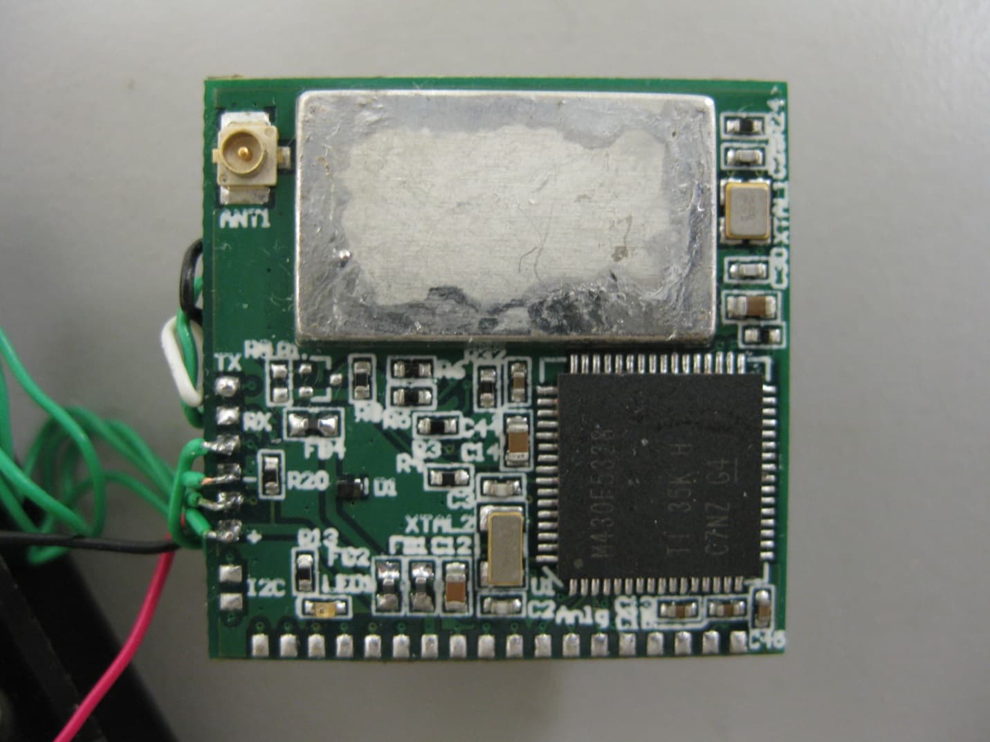
Click to zoom
Application Details
- Equipment Class
- DTS - Digital Transmission System
- Date of Grant
- Feb 13, 2014
- Application Purpose
- Original Equipment
- Date of Application
- Feb 10, 2014
- Equipment Note
- 2.4 GHz Transceiver
- Frequency Range
- 2424.00000000 - 2457.00000000
- Company
- KCF Technologies, Inc.
- Country
- United States
Documents & Files
Document Text
Text extracted from the exhibit documents filed with the FCC. Open a document above to read the original.
Users Manual
KCF Technologies, Inc. | 336 South Fraser Street, State College PA 16803 | 814.867.4097 | www.kcftech.com SD 2.0 Wireless Radio User Guide Version 1.0 12/6/13 Copyright © 2013 KCF Technologies, Inc. All rights reserved 2 | K C F T e c h n o l o g ie s S D 2 . 0 W i r e l e s s R a d i o U s e r G u i d e Revision History Revision Date Note 1.0 12/6/13 -- Table of Contents General Description 3 Performance Specifications 4 Physical Dimensions 5 FCC Compliance Information 6 3 | K C F T e c h n o l o g ie s S D 2 . 0 W i r e l e s s R a d i o U s e r G u i d e General Description The SD 2.0 Wireless Radio is a 2.4 GHz 2-way radio module intended for wireless transmission of sensor data. The board’s small package and modular design facilitate integration with a wide range of sensors, and in particular it is designed to be permanently mounted to KCF’s line of Smart Diagnostics sensors. The radio features a proprietary multi-frequency network protocol to allow simple setup and operation of up to 100 sensor nodes per receiver, making it an ideal solution for multi-point monitoring of industrial equipment. The communication protocol of the radio is highly configurable to allow tailoring of data collection to numerous different applications. Sampling rate, collection interval, input channels, etc. are all adjustable by the user. The radio is designed to be attached via land-grid-array (LGA) soldering to the sensor board it is serving, thereby minimizing the size of the entire sensor/radio package and eliminating the size, expense, and long term reliability risks of a connector. The radio is powered via the LGA connection to the sensor board. The radio communicates using an antenna provided by KCF which attaches to the radio module using a standard U.FL connector. 4 | K C F T e c h n o l o g ie s S D 2 . 0 W i r e l e s s R a d i o U s e r G u i d e Performance Specifications Wireless Module RF Frequency Band 2.4 GHz ISM band Data rates 2000 kbps Modulation GFSK Channel spacing 6 MHz Receive sensitivity -90 dB at 2000 kbps Acknowledgement Hardware level auto-acknowledgement Retransmission Hardware level 0-35x Microcontroller Digital I/O 47 ADC inputs 10 external - 12 bit SAR RAM 10k Flash 128k Physical Mass 3.5 grams Mount LGA Antenna port Hirose U.FL Temperature -40 to+ 85C RoHS Compliant Voltage 2.7-3.6 V (Recommend Duracell CR123A Battery) Programming interface Spy-Bi-Wire (serialized JTAG) Certification FCC/ETIS Pending 5 | K C F T e c h n o l o g ie s S D 2 . 0 W i r e l e s s R a d i o U s e r G u i d e Physical Dimensions Note: Dimensions in inches, tolerance is +/- 0.010 6 | K C F T e c h n o l o g ie s S D 2 . 0 W i r e l e s s R a d i o U s e r G u i d e FCC Compliance Information FCC ID: Z5ISD2 This device complies with part 15 of the FCC Rules. Operation is subject to the following two conditions: (1) This device may not cause harmful interference, and (2) this device must accept any interference received, including interference that may cause undesired operation. Changes or modifications to this device (including operating at different power levels or substituting a different antenna) not expressly approved by KCF Technologies, Inc. may void the user’s authority to operate this equipment. NOTE: This equipment has been tested and found to comply with the limits for a Class B digital device, pursuant to part 15 of the FCC Rules. These limits are designed to provide reasonable protection against harmful interference in a residential installation. This equipment generates, uses and can radiate radio frequency energy and, if not installed and used in accordance with the instructions, may cause harmful interference to radio communications. However, there is no guarantee that interference will not occur in a particular installation. If this equipment does cause harmful interference to radio or television reception, which can be determined by turning the equipment off and on, the user is encouraged to try to correct the interference by one or more of the following measures: Reorient or relocate the receiving antenna. Increase the separation between the equipment and receiver. Connect the equipment into an outlet on a circuit different from that to which the receiver is connected. Consult the dealer or an experienced radio/TV technician for help. CAUTION: to minimize RF exposure it is recommended to maintain a minimum separation of 20cm between the device and the user during operation.
Cover Letter(s)
Applicant/Grantee KCF Technologies FCC ID: Z5ISD2 Section 15.212 Modular Transmitters Request for Modular Approval Request for Limited Modular Approval Requirements EUT Conditions Comply (Y/N) Single Modular Approval Requirements 1 The radio elements of the modular transmitter must have their own shielding. The physical crystal and tuning capacitors may be located external to the shielded radio elements. Device is equipped with Metal shielding to cover RF section. Y 2 The modular transmitter must have buffered modulation/data inputs (if such inputs are provided) to ensure that the module will comply with Part 15 requirements under conditions of excessive data rates or over-modulation. All inputs to the modules are buffered through logic or microprocessor inputs. Y 3 The modular transmitter must have its own power supply regulation. For application with sensor device is powered by nominal 3.0V battery (3.2V new battery typical). For PC attached mode KCF requires use of a voltage regulator to limit applied voltage to be the same as battery voltage. N 4 The modular transmitter must comply with the antenna and transmission system requirements of Sections 15.203, 15.204(b) and 15.204(c). The antenna must either be permanently attached or employ a “unique” antenna coupler (at all connections between the module and the antenna, including the cable). The “professional installation” provision of Section 15.203 is not applicable to modules but can apply to limited modular approvals under paragraph (b) of this section. Device is equipped with unique antenna connector (U.FL). Y Page 2 of 4 UL LLC 12 LABORATORY DR., RESEARCH TRIANGLE PARK, NC 27709 TEL: (919) 549-1400 Applicant/Grantee KCF Technologies FCC ID: Z5ISD2 Section 15.212 Modular Transmitters Request for Modular Approval Request for Limited Modular Approval Requirements EUT Conditions Comply (Y/N) Single Modular Approval Requirements 5 The modular transmitter must be tested in a stand-alone configuration, i.e., the module must not be inside another device during testing for compliance with Part 15 requirements. Unless the transmitter module will be battery powered, it must comply with the AC line conducted requirements found in Section 15.207. AC or DC power lines and data input/output lines connected to the module must not contain ferrites, unless they will be marketed with the module (see Section 15.27(a)). The length of these lines shall be the length typical of actual use or, if that length is unknown, at least 10 centimeters to insure that there is no coupling between the case of the module and supporting equipment. Any accessories, peripherals, or support equipment connected to the module during testing shall be unmodified and commercially available (see Section 15.31(i)). Device was tested standalone on tabletop using a DC power supply. Data lines are connected to an attached USB interface board. Device was not placed inside an enclosure. Y Page 3 of 4 UL LLC 12 LABORATORY DR., RESEARCH TRIANGLE PARK, NC 27709 TEL: (919) 549-1400 Applicant/Grantee KCF Technologies FCC ID: Z5ISD2 Section 15.212 Modular Transmitters Request for Modular Approval Request for Limited Modular Approval Requirements EUT Conditions Comply (Y/N) Single Modular Approval Requirements 6 The modular transmitter must be equipped with either a permanently affixed label or must be capable of electronically displaying its FCC identification number. (A) If using a permanently affixed label, the modular transmitter must be labeled with its own FCC identification number, and, if the FCC identification number is not visible when the module is installed inside another device, then the outside of the device into which the module is installed must also display a label referring to the enclosed module. This exterior label can use wording such as the following: “Contains Transmitter Module FCC ID: XYZMODEL1” or “Contains FCC ID: XYZMODEL1.” Any similar wording that expresses the same meaning may be used. The Grantee may either provide such a label, an example of which must be included in the application for equipment authorization, or, must provide adequate instructions along with the module which explain this requirement. In the latter case, a copy of these instructions must be included in the application for equipment authorization. (B) If the modular transmitter uses an electronic display of the FCC identification number, the information must be readily accessible and visible on the modular transmitter or on the device in which it is installed. If the module is installed inside another device, then the outside of the device into which the module is installed must display a label referring to the enclosed module. This exterior label can use wording such as the following: “Contains FCC certified transmitter module(s).” Any similar wording that expresses the same meaning may be used. The user manual must include instructions on how to access the electronic display. A copy of these instructions must be included in the application for equipment authorization. The label will be placed on the RF shield of the module. Y Page 4 of 4 UL LLC 12 LABORATORY DR., RESEARCH TRIANGLE PARK, NC 27709 TEL: (919) 549-1400 Applicant/Grantee KCF Technologies FCC ID: Z5ISD2 Section 15.212 Modular Transmitters Request for Modular Approval Request for Limited Modular Approval Requirements EUT Conditions Comply (Y/N) Single Modular Approval Requirements 7 The modular transmitter must comply with any specific rules or operating requirements that ordinarily apply to a complete transmitter and the manufacturer must provide adequate instructions along with the module to explain any such requirements. A copy of these instructions must be included in the application for equipment authorization. Operation software limits user to selecting frequency and power within the settings proven in this application. Timing is fixed by firmware and cannot exceed the timing shown in the test report. Y 8 The modular tran…
Text truncated - open the document above for the full version.
External Photos
REPORT NO: R10101315-RF DATE: 2014-01-15 FCC ID: Z5ISD2 Page 1 of 3 UL LLC 12 LABORATORY DR., RESEARCH TRIANGLE PARK, NC 27709 TEL: (919) 549-1400 External Photos – KCF Technologies, model SD2 Overall System Config. for Testing REPORT NO: R10101315-RF DATE: 2014-01-15 FCC ID: Z5ISD2 Page 2 of 3 UL LLC 12 LABORATORY DR., RESEARCH TRIANGLE PARK, NC 27709 TEL: (919) 549-1400 Model SD2, Top View REPORT NO: R10101315-RF DATE: 2014-01-15 FCC ID: Z5ISD2 Page 3 of 3 UL LLC 12 LABORATORY DR., RESEARCH TRIANGLE PARK, NC 27709 TEL: (919) 549-1400 Model SD2, Bottom View
ID Label/Location Info
ID: Z5ISD2 www.kcftech.com KX-008-127 SD2.0 WIRELESS BOARD
Internal Photos
REPORT NO: R10101315-RF DATE: 2014-01-15 FCC ID: Z5ISD2 Page 1 of 7 UL LLC 12 LABORATORY DR., RESEARCH TRIANGLE PARK, NC 27709 TEL: (919) 549-1400 Internal Photos – KCF Technologies, model SD2 Model SD2, Top View with Shield Removed REPORT NO: R10101315-RF DATE: 2014-01-15 FCC ID: Z5ISD2 Page 2 of 7 UL LLC 12 LABORATORY DR., RESEARCH TRIANGLE PARK, NC 27709 TEL: (919) 549-1400 Model SD2, Top View with Bottom Board Removed from Main Bottom REPORT NO: R10101315-RF DATE: 2014-01-15 FCC ID: Z5ISD2 Page 3 of 7 UL LLC 12 LABORATORY DR., RESEARCH TRIANGLE PARK, NC 27709 TEL: (919) 549-1400 Model SD2, Bottom View (Main Board and Daughter Board) REPORT NO: R10101315-RF DATE: 2014-01-15 FCC ID: Z5ISD2 Page 4 of 7 UL LLC 12 LABORATORY DR., RESEARCH TRIANGLE PARK, NC 27709 TEL: (919) 549-1400 Model SD2, Bottom View (Main Board) REPORT NO: R10101315-RF DATE: 2014-01-15 FCC ID: Z5ISD2 Page 5 of 7 UL LLC 12 LABORATORY DR., RESEARCH TRIANGLE PARK, NC 27709 TEL: (919) 549-1400 Antenna Used during testing REPORT NO: R10101315-RF DATE: 2014-01-15 FCC ID: Z5ISD2 Page 6 of 7 UL LLC 12 LABORATORY DR., RESEARCH TRIANGLE PARK, NC 27709 TEL: (919) 549-1400 Antenna Used During Testing REPORT NO: R10101315-RF DATE: 2014-01-15 FCC ID: Z5ISD2 Page 7 of 7 UL LLC 12 LABORATORY DR., RESEARCH TRIANGLE PARK, NC 27709 TEL: (919) 549-1400 Antenna Connection Used During Testing
Operational Description
Smart Diagnostic Wireless Description Smart Diagnostic (SD) is an intelligent wireless network solution that will send sensor data over the 2.4GHz ISM band to a receiver which then transports the data serially to a PC, laptop, collection server, cloud, etc. for evaluation. This wireless board can be attached to many different types of both analog and digital sensors. These nodes can operate from a single CR123A 3.0V or 3.6V battery and the receiver operates from power off of a USB connection. The current network topology supported is a star. The microprocessor can be configured to capture a certain amount of data (depending on the sensor attached) on the node, at which time it wakes up the radio and begins sending data serially to it for transmission. The microprocessor and the radio communicate via a SPI bus. A given network operates on a distinct frequency with the 2.4GHz ISM band. The network does NOT use frequency hopping spread spectrum. It can however use a form of agility in a multi-receiver environment when poor radio quality on a given frequency has been determined. The radio uses GFSK modulation with a fixed over the air rate. The radio inherently has the ability to turn itself around as a receiver, in what is known as Enhanced ShockBurst, for a short duration after transmission to automatically listen for acknowledgements and or commands. Topside software (GUI) controls the data acquisition rate and the periodicity with which this is done, depending on the sensor attached. This in turn controls the amount of over the air RF activity. Sensor data from the node is sent over the air in blocks of at most 329 bits (hardware overhead, software overhead and payload). Each block can be retransmitted if necessary in the event of a poor radio frequency link. These blocks are packaged together to form packets.
RF Exposure Info
NVLAP LAB CODE 200246-0 FCC Part 1 Subpart I FCC Part 2 Subpart J INDUSTRY CANADA RSS 102 ISSUE 3 RF EXPOSURE REPORT FOR 2.4 GHz TRANSCEIVER MODEL NUMBER: SD2 FCC ID: Z5ISD2 REPORT NUMBER: R10101315-MPE ISSUE DATE: 2014-01-17 REVISED DATE: 2014-02-10 Prepared for KCF TECHNOLOGIES 336 S FRASER ST . STATE COLLEGE, PA 16801 Prepared by UL LLC 12 LABORATORY DR. RESEARCH TRIANGLE PARK, NC 27709 USA TEL: (919) 549-1400 REPORT NO: R10101315-MPE DATE: 2014-01-17 FCC ID: Z5ISD2 REVISED: 2014-02-10 Page 2 of 11 UL LLC FORM NO: CCSUP4701I 12 LABORATORY DR., RESEARCH TRIANGLE PARK, NC 27709 TEL: (919) 549-1400 This report shall not be reproduced except in full, without the written approval of UL LLC Revision History Rev. Issue Date Revisions Revised By -- 2014-01-17 Initial Issue Jeff Moser 1 2014-02-05 Revised output power to consider manufacturer’s specified tolerance. Jeff Moser 2 2014-02-10 Revised RF Exposure Table, page 11. Jeff Moser REPORT NO: R10101315-MPE DATE: 2014-01-17 FCC ID: Z5ISD2 REVISED: 2014-02-10 Page 3 of 11 UL LLC FORM NO: CCSUP4701I 12 LABORATORY DR., RESEARCH TRIANGLE PARK, NC 27709 TEL: (919) 549-1400 This report shall not be reproduced except in full, without the written approval of UL LLC TABLE OF CONTENTS 1. ATTESTATION OF TEST RESULTS ................................................................................. 4 2. TEST METHODOLOGY ..................................................................................................... 5 3. REFERENCES ................................................................................................................... 5 4. FACILITIES AND ACCREDITATION ................................................................................. 5 5. MAXIMUM PERMISSIBLE RF EXPOSURE ....................................................................... 6 5.1. FCC RULES ................................................................................................................ 6 5.2. IC RULES .................................................................................................................... 7 5.3. EQUATIONS ................................................................................................................ 8 5.4. LIMITS AND IC EXEMPTION .....................................................................................10 6. RF EXPOSURE RESULTS ................................................................................................11 REPORT NO: R10101315-MPE DATE: 2014-01-17 FCC ID: Z5ISD2 REVISED: 2014-02-10 Page 4 of 11 UL LLC FORM NO: CCSUP4701I 12 LABORATORY DR., RESEARCH TRIANGLE PARK, NC 27709 TEL: (919) 549-1400 This report shall not be reproduced except in full, without the written approval of UL LLC 1. ATTESTATION OF TEST RESULTS COMPANY NAME: KCF TECHNOLOGIES 333 S. FRASER ST. STATE COLLEGE, PA 16801, U.S.A EUT DESCRIPTION: SD2 is a 2.4 GHz transceiver that is intended for use with the SD vibration system. The SD vibration system consists of a battery operated Vibration Sensor (SD-VSN-2) and a USB powered Primary Receive Node (SD-PRN-2). MODEL: SD2 SERIAL NUMBER: 0xFCC00001 DATE TESTED: 2013-10-28 through 2013-12-13 APPLICABLE STANDARDS STANDARD TEST RESULTS FCC PART 1 SUBPART I & PART 2 SUBPART J Pass INDUSTRY CANADA RSS 102 ISSUE 3 Pass UL LLC calculated the RF Exposure of the above equipment in accordance with the requirements set forth in the above standards, using test results reported in the test report documents referenced below and/or documentation furnished by the applicant. All indications of Pass/Fail in this report are opinions expressed by UL LLC based on interpretations of these calculations. The results show that the equipment is capable of demonstrating compliance with the requirements as documented in this report. Note: The results documented in this report apply only to the tested sample, under the conditions and modes of operation as described herein. This document may not be altered or revised in any way unless done so by UL LLC and all revisions are duly noted in the revisions section. Any alteration of this document not carried out by UL LLC will constitute fraud and shall nullify the document. This report must not be used by the client to claim product certification, approval, or endorsement by NVLAP, NIST, any agency of the Federal Government, or any agency of any government. Approved & Released For UL LLC By: Prepared By: Michael Antola Jeff Moser EMC Project Lead EMC Program Manager UL - WiSE UL - WiSE Wireless, Interoperability, Security/Payments & EMC REPORT NO: R10101315-MPE DATE: 2014-01-17 FCC ID: Z5ISD2 REVISED: 2014-02-10 Page 5 of 11 UL LLC FORM NO: CCSUP4701I 12 LABORATORY DR., RESEARCH TRIANGLE PARK, NC 27709 TEL: (919) 549-1400 This report shall not be reproduced except in full, without the written approval of UL LLC 2. TEST METHODOLOGY All calculations were made in accordance with FCC OET Bulletin 65 Edition 97-01 and IC Safety Code 6. 3. REFERENCES All measurements were made as documented in UL LLC test report No. R10101315-RF, for operation in the 2.4 GHz band. Output power, Duty cycle and Antenna gain data is excerpted from the applicable test reports. Antenna gain data is excerpted from the applicable test reports. 4. FACILITIES AND ACCREDITATION The test sites and measurement facilities used to collect data are located at 12 Laboratory Dr., Research Triangle Park, NC 27709, USA. UL LLC (RTP) is accredited by NVLAP, Laboratory Code 200246-0. The full scope of accreditation can be viewed at http://ts.nist.gov/standards/scopes/2002460.htm . REPORT NO: R10101315-MPE DATE: 2014-01-17 FCC ID: Z5ISD2 REVISED: 2014-02-10 Page 6 of 11 UL LLC FORM NO: CCSUP4701I 12 LABORATORY DR., RESEARCH TRIANGLE PARK, NC 27709 TEL: (919) 549-1400 This report shall not be reproduced except in full, without the written approval of UL LLC 5. MAXIMUM PERMISSIBLE RF EXPOSURE 5.1. FCC RULES §1.1310 The criteria listed in Table 1 shall be used to evaluate the environmental i…
Text truncated - open the document above for the full version.
Test Report
NVLAP LAB CODE 200246-0 FCC 47 CFR PART 15 SUBPART C INDUSTRY CANADA RSS-210 ISSUE 8 CERTIFICATION TEST REPORT FOR 2.4 GHz TRANSCEIVER MODEL NUMBER: SD2 FCC ID: Z5ISD2 REPORT NUMBER: R10101315-RF ISSUE DATE: JANUARY 15, 2014 REVISED: FEBRUARY 10, 2014 Prepared for KCF TECHNOLOGIES 336 S FRASER ST. STATE COLLEGE, PA 16801 Prepared by UL LLC 12 LABORATORY DR. RESEARCH TRIANGLE PARK, NC 27709 USA TEL: (919) 549-1400 REPORT NO: R10101315-RF DATE: 2014-01-15 FCC ID: Z5ISD2 REVISED: 2014-02-10 Page 2 of 63 UL LLC FORM NO: CCSUP4701I 12 LABORATORY DR., RESEARCH TRIANGLE PARK, NC 27709 TEL: (919) 549-1400 This report shall not be reproduced except in full, without the written approval of UL LLC Revision History Rev. Issue Date Revisions Revised By -- 2014-01-15 Initial Issue Jeff Moser 1 2014-02-10 Revised to remove FCC Inquiry Exhibit (Sec. 7.1) Jeff Moser REPORT NO: R10101315-RF DATE: 2014-01-15 FCC ID: Z5ISD2 REVISED: 2014-02-10 Page 3 of 63 UL LLC FORM NO: CCSUP4701I 12 LABORATORY DR., RESEARCH TRIANGLE PARK, NC 27709 TEL: (919) 549-1400 This report shall not be reproduced except in full, without the written approval of UL LLC TABLE OF CONTENTS 1. ATTESTATION OF TEST RESULTS ................................................................................. 4 2. TEST METHODOLOGY ..................................................................................................... 5 3. FACILITIES AND ACCREDITATION ................................................................................. 5 4. CALIBRATION AND UNCERTAINTY ................................................................................ 5 4.1. MEASURING INSTRUMENT CALIBRATION .............................................................. 5 4.2. SAMPLE CALCULATION ............................................................................................ 5 4.3. MEASUREMENT UNCERTAINTY ............................................................................... 5 5. EQUIPMENT UNDER TEST ............................................................................................... 6 5.1. DESCRIPTION OF EUT .............................................................................................. 6 5.2. MAXIMUM OUTPUT POWER...................................................................................... 6 5.3. DESCRIPTION OF AVAILABLE ANTENNAS .............................................................. 6 5.4. SOFTWARE AND FIRMWARE .................................................................................... 6 5.5. WORST-CASE CONFIGURATION AND MODE .......................................................... 7 5.6. DESCRIPTION OF TEST SETUP ................................................................................ 8 6. TEST AND MEASUREMENT EQUIPMENT ......................................................................10 7. ANTENNA PORT TEST RESULTS ...................................................................................12 7.1. DUTY CYCLE .............................................................................................................12 7.2. TRANSMIT MODE IN THE 2.4 GHz BAND.................................................................16 7.2.1. 6 dB BANDWIDTH ...............................................................................................16 7.2.2. 99% BANDWIDTH ...............................................................................................20 7.2.3. OUTPUT POWER ...............................................................................................24 7.2.4. AVERAGE POWER .............................................................................................28 7.2.5. POWER SPECTRAL DENSITY ...........................................................................29 7.2.6. CONDUCTED SPURIOUS EMISSIONS ..............................................................33 8. RADIATED TEST RESULTS .............................................................................................40 8.1. LIMITS AND PROCEDURE ........................................................................................40 8.2. TRANSMITTER ABOVE 1 GHz ..................................................................................41 8.2.1. TX ABOVE 1 GHz FOR TRANSMIT MODE IN THE 2.4 GHz BAND ...................41 8.3. WORST-CASE BELOW 1 GHz ...................................................................................55 9. AC POWER LINE CONDUCTED EMISSIONS ..................................................................59 REPORT NO: R10101315-RF DATE: 2014-01-15 FCC ID: Z5ISD2 REVISED: 2014-02-10 Page 4 of 63 UL LLC FORM NO: CCSUP4701I 12 LABORATORY DR., RESEARCH TRIANGLE PARK, NC 27709 TEL: (919) 549-1400 This report shall not be reproduced except in full, without the written approval of UL LLC 1. ATTESTATION OF TEST RESULTS COMPANY NAME: KCF TECHNOLOGIES 333 S. FRASER ST. STATE COLLEGE, PA 16801, U.S.A EUT DESCRIPTION: SD2 is a 2.4 GHz transceiver that is intended for use with the SD vibration system. The SD vibration system consists of a battery operated Vibration Sensor (SD-VSN-2) and a USB powered Primary Receive Node (SD-PRN-2). MODEL: SD2 SERIAL NUMBER: 0xFCC00001 DATE TESTED: 2013-10-28 through 2013-12-13 APPLICABLE STANDARDS STANDARD TEST RESULTS CFR 47 Part 15 Subpart C Pass INDUSTRY CANADA RSS-210 Issue 8 Annex 8 Pass INDUSTRY CANADA RSS-GEN Issue 3 Pass UL LLC tested the above equipment in accordance with the requirements set forth in the above standards. All indications of Pass/Fail in this report are opinions expressed by UL LLC based on interpretations and/or observations of test results. Measurement Uncertainties were not taken into account and are published for informational purposes only. The test results show that the equipment tested is capable of demonstrating compliance with the requirements as documented in this report. Note: The results documented in this report apply only to the tested sample, under the conditions and modes of…
Text truncated - open the document above for the full version.
Test Setup Photos
REPORT NO: R10101315-RF DATE: 2014-01-15 FCC ID: Z5ISD2 Page 1 of 9 UL LLC 12 LABORATORY DR., RESEARCH TRIANGLE PARK, NC 27709 TEL: (919) 549-1400 1. SETUP PHOTOS ANTENNA PORT CONDUCTED RF MEASUREMENT SETUP ANTENNA PORT CONDUCTED PHOTO REPORT NO: R10101315-RF DATE: 2014-01-15 FCC ID: Z5ISD2 Page 2 of 9 UL LLC 12 LABORATORY DR., RESEARCH TRIANGLE PARK, NC 27709 TEL: (919) 549-1400 RADIATED RF MEASUREMENT SETUP (BELOW 1 GHz) RADIATED FRONT PHOTO (BELOW 1 GHz) REPORT NO: R10101315-RF DATE: 2014-01-15 FCC ID: Z5ISD2 Page 3 of 9 UL LLC 12 LABORATORY DR., RESEARCH TRIANGLE PARK, NC 27709 TEL: (919) 549-1400 RADIATED BACK PHOTO (BELOW 1 GHz) REPORT NO: R10101315-RF DATE: 2014-01-15 FCC ID: Z5ISD2 Page 4 of 9 UL LLC 12 LABORATORY DR., RESEARCH TRIANGLE PARK, NC 27709 TEL: (919) 549-1400 RADIATED RF MEASUREMENT SETUP (ABOVE 1 GHz) RADIATED FRONT PHOTO (ABOVE 1 GHz) REPORT NO: R10101315-RF DATE: 2014-01-15 FCC ID: Z5ISD2 Page 5 of 9 UL LLC 12 LABORATORY DR., RESEARCH TRIANGLE PARK, NC 27709 TEL: (919) 549-1400 RADIATED BACK PHOTO (ABOVE 1 GHz) REPORT NO: R10101315-RF DATE: 2014-01-15 FCC ID: Z5ISD2 Page 6 of 9 UL LLC 12 LABORATORY DR., RESEARCH TRIANGLE PARK, NC 27709 TEL: (919) 549-1400 RADIATED RF WORST-CASE INVESTIGATION AT FUNDAMENTAL SET-UP X Orientation Y Orientation REPORT NO: R10101315-RF DATE: 2014-01-15 FCC ID: Z5ISD2 Page 7 of 9 UL LLC 12 LABORATORY DR., RESEARCH TRIANGLE PARK, NC 27709 TEL: (919) 549-1400 This orientation proved to be the worst-case. Therefore, it was used throughout testing. Testing in this orientation with the battery replaced by a power supply showed no appreciable difference in emissions at the fundamental. Therefore, a power supply was used during the remaining test program. Z Orientation (WORST CASE ORIENTATION) REPORT NO: R10101315-RF DATE: 2014-01-15 FCC ID: Z5ISD2 Page 8 of 9 UL LLC 12 LABORATORY DR., RESEARCH TRIANGLE PARK, NC 27709 TEL: (919) 549-1400 POWERLINE CONDUCTED EMISSIONS MEASUREMENT SETUP LINE CONDUCTED FRONT PHOTO REPORT NO: R10101315-RF DATE: 2014-01-15 FCC ID: Z5ISD2 Page 9 of 9 UL LLC 12 LABORATORY DR., RESEARCH TRIANGLE PARK, NC 27709 TEL: (919) 549-1400 LINE CONDUCTED BACK PHOTO
Contact Information
Applicant
Jeremy Frank
Test Firm
UL LLCRick Titus
Technical Specifications
| # | Rule Parts | Frequency Range | Power Output |
|---|---|---|---|
| 1 | 15C | 2.42 GHz - 2.46 GHz | 36.40 mW |
Other Applications from KCF Technologies, Inc.
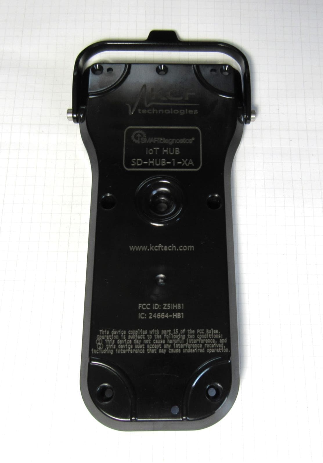
Z5IHB1
Sep 20, 2020loT Sensor Hub
Equipment Class
DTS - Digital Transmission System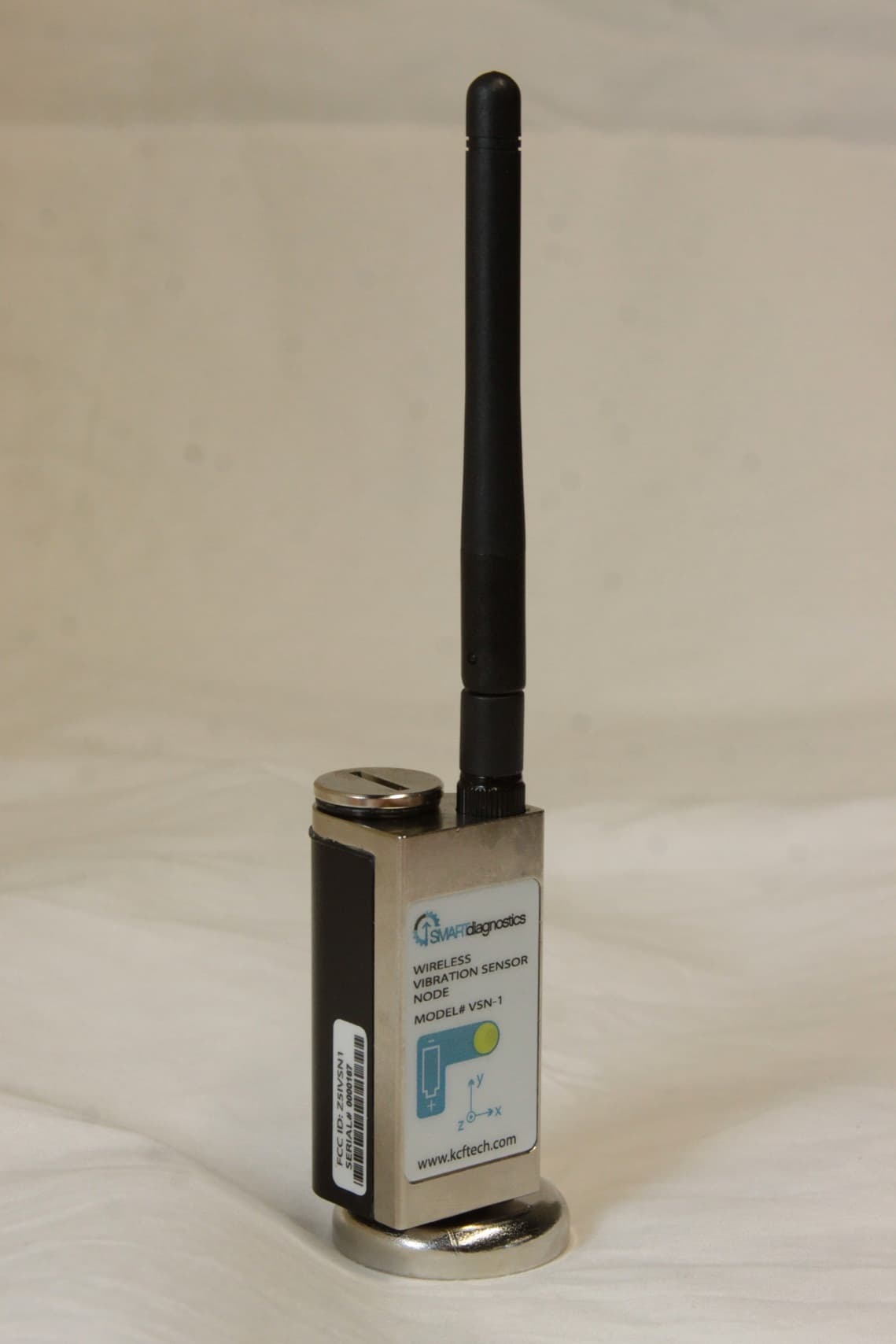
Z5IVSN1
May 07, 2012Wireless Vibration Monitoring System
Equipment Class
DSS - Part 15 Spread Spectrum Transmitter