Z5N-7AM13Touch Switch
LOONG YEE Industry CO., LTD.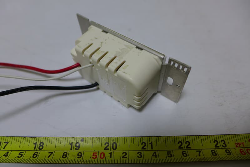
Click to zoom
Application Details
- Equipment Class
- DXX - Part 15 Low Power Communication Device Transmitter
- Date of Grant
- Dec 20, 2015
- Application Purpose
- Original Equipment
- Date of Application
- Dec 17, 2015
- Equipment Note
- Touch Switch
- Frequency Range
- 2409.00000000 - 2409.00000000
- Company
- LOONG YEE Industry CO., LTD.
- Country
- Taiwan
Documents & Files
Document Text
Text extracted from the exhibit documents filed with the FCC. Open a document above to read the original.
Users Manual
1 1 Key Neutral Touch Switch (LR3A-M13)Specification Per channel lighting load (350 Watts) Lighting overload protect function Lighting switch over temperature protect function Auto lighting turn off delay function Relay protecting circuit AC Full range input:100~240V AC 2.4G RF Remote Control LR3A-M13 L6N5A-AW Front View Specification 2 Touch Switch wiring circuit When the touch switch circuit loop, if installed too many lamps, switch will detect the loop current after turn on the lighting, touch switch normal operating current is 3.5A (amps), once the instantaneous current detection circuit exceeds 6.5A (amps), touch switch will automatically power-off , Buzzer (beeper) will beep sound after 10 stops, At the same time light control switch delay the function stop of 30 seconds, touch function is inactive during this period, when the touch function recovery, and lighting control switch function stop, please kindly check the lighting circuit. If the lamp lighting control switch in the ON state when the touch switch detects the ambient temperature above 75 °C ± 5%, the internal over-temperature protection circuit will immediately power off, wait until the temperature drops below to 60 °C ± 5% , The protection circuit automatically back to function state, when the pre to this case, please kindly check the lighting loop circuit. Lighting control switch can set the delay time of 5 minutes turn off the lights. Over Load Over Temperature Delay Time 100~240VAC (60/50 Hz) Junction BOX 1 Key Neutral Touch Switch (LR3A-M13) Neutral Neutral Fire Wire 3 AC input 100~240V AC (60/50 Hz) RF remote distance 12 Meter Touch switch load 350W Time delay turn off 1 Minutes Over load >350W +30% Over temperature >75°C ±5% turn off;60°C ±5% Back to function Electrical Characteristics 4 FCC Statement This equipment has been tested and found to comply with the limits for a Class B digital device, pursuant to part 15 of the FCC Rules. These limits are designed to provide reasonable protection against harmful interference in a residential installation. This equipment generates, uses and can radiate radio frequency energy and, if not installed and used in accordance with the instructions, may cause harmful interference to radio communications. However, there is no guarantee that interference will not occur in a particular installation. If this equipment does cause harmful interference to radio or television reception, which can be determined by turning the equipment off and on, the user is encouraged to try to correct the interference by one or more of the following measures: —Reorient or relocate the receiving antenna. —Increase the separation between the equipment and receiver. —Connect the equipment into an outlet on a circuit different from that to which the receiver is connected. —Consult the dealer or an experienced radio/TV technician for help. FCC Radiation Exposure Statement This device complies with FCC radiation exposure limits set forth for an uncontrolled environment and it also complies with Part 15 of the FCC RF Rules. This equipment must be installed and operated in accordance with provided instructions and the antenna(s) used for this transmitter must be installed to provide a separation distance of at least 20 cm from all persons and must not be co-located or operating in conjunction with any other antenna or transmitter. End-users and installers must be provided with antenna installation instructions and consider removing the no-collocation statement. This device complies with Part 15 of the FCC Rules. Operation is subject to the following two conditions: (1) this device may not cause harmful interference, and (2) this device must accept any interference received, including interference that may cause undesired operation. Caution! 1. Any changes or modifications not expressly approved by the party responsible for compliance could void the user's authority to operate the equipment. 2. Indoor use only
Users Manual
1 1key Neutral Touch Switch(LR7A-M13) Specification Per channel lighting load (700 Watts) Lighting overload protect function Lighting switch over temperature protect function Auto lighting turn off delay function Relay protecting circuit AC Full range input:100~240V AC 2.4G RF Remote Control LR7A-M13 L6N5A-AW Front View Specification 2 Touch Switch wiring circuit When the touch switch circuit loop, if installed too many lamps, switch will detect the loop current after turn on the lighting, touch switch normal operating current is 7A (amps), once the instantaneous current detection circuit exceeds 13A (amps), touch switch will automatically power-off , Buzzer (beeper) will beep sound after 10 stops, At the same time light control switch delay the function stop of 30 seconds, touch function is inactive during this period, when the touch function recovery, and lighting control switch function stop, please kindly check the lighting circuit. If the lamp lighting control switch in the ON state when the touch switch detects the ambient temperature above 75 °C ± 5%, the internal over-temperature protection circuit will immediately power off, wait until the temperature drops below to 60 °C ± 5% , The protection circuit automatically back to function state, when the pre to this case, please kindly check the lighting loop circuit. Lighting control switch can set the delay time of 5 minutes turn off the lights. Over Load Over Temperature Delay Time 1 Key Neutral Tuuch switch (LR7A-M13) 100~240VAC (60/50 Hz) Junction BOX Frie Wire Neutral Neutral 3 AC input 100~240V AC (60/50 Hz) RF remote distance 12 Meter Touch switch load 700W Time delay turn off 1 Minutes Over load >700W +30% Over temperature >75°C ±5% turn off;60°C ±5% Back to function Electrical Characteristics 4 FCC Statement This equipment has been tested and found to comply with the limits for a Class B digital device, pursuant to part 15 of the FCC Rules. These limits are designed to provide reasonable protection against harmful interference in a residential installation. This equipment generates, uses and can radiate radio frequency energy and, if not installed and used in accordance with the instructions, may cause harmful interference to radio communications. However, there is no guarantee that interference will not occur in a particular installation. If this equipment does cause harmful interference to radio or television reception, which can be determined by turning the equipment off and on, the user is encouraged to try to correct the interference by one or more of the following measures: —Reorient or relocate the receiving antenna. —Increase the separation between the equipment and receiver. —Connect the equipment into an outlet on a circuit different from that to which the receiver is connected. —Consult the dealer or an experienced radio/TV technician for help. FCC Radiation Exposure Statement This device complies with FCC radiation exposure limits set forth for an uncontrolled environment and it also complies with Part 15 of the FCC RF Rules. This equipment must be installed and operated in accordance with provided instructions and the antenna(s) used for this transmitter must be installed to provide a separation distance of at least 20 cm from all persons and must not be co-located or operating in conjunction with any other antenna or transmitter. End-users and installers must be provided with antenna installation instructions and consider removing the no-collocation statement. This device complies with Part 15 of the FCC Rules. Operation is subject to the following two conditions: (1) this device may not cause harmful interference, and (2) this device must accept any interference received, including interference that may cause undesired operation. Caution! 1. Any changes or modifications not expressly approved by the party responsible for compliance could void the user's authority to operate the equipment. 2. Indoor use only
External Photos
Project No.: 1507004 Page 2 of 15 LR7A-M13 Project No.: 1507004 Page 3 of 15 LR3A-M13
ID Label/Location Info
Label location
Internal Photos
Project No.: 1507004 Page 4 of 15 LR7A-M13 Project No.: 1507004 Page 5 of 15 Project No.: 1507004 Page 6 of 15 Project No.: 1507004 Page 7 of 15 Project No.: 1507004 Page 8 of 15 Project No.: 1507004 Page 9 of 15 Project No.: 1507004 Page 10 of 15 LR3A-M13 Project No.: 1507004 Page 11 of 15 Project No.: 1507004 Page 12 of 15 Project No.: 1507004 Page 13 of 15 Project No.: 1507004 Page 14 of 15 Project No.: 1507004 Page 15 of 15
Test Setup Photos
Report No.: BTL-FCCP-1-1507004 Page 22 of 54 7. EUT TEST PHOTO Conducted Measurement Photos-LR7A-M13 Report No.: BTL-FCCP-1-1507004 Page 23 of 54 Conducted Measurement Photos-LR3A-M13 Report No.: BTL-FCCP-1-1507004 Page 24 of 54 Radiated Measurement Photos-LR7A-M13 9KHz to 30MHz Report No.: BTL-FCCP-1-1507004 Page 25 of 54 Radiated Measurement Photos-LR3A-M13 9KHz to 30MHz Report No.: BTL-FCCP-1-1507004 Page 26 of 54 Radiated Measurement Photos-LR7A-M13 30MHz to 1000MHz Report No.: BTL-FCCP-1-1507004 Page 27 of 54 Radiated Measurement Photos-LR3A-M13 30MHz to 1000MHz Report No.: BTL-FCCP-1-1507004 Page 28 of 54 Radiated Measurement Photos-LR7A-M13 Above 1000MHz Report No.: BTL-FCCP-1-1507004 Page 29 of 54 Radiated Measurement Photos-LR3A-M13 Above 1000MHz
Contact Information
Applicant
Jack Chang(Engineer)
Technical Contact
Non-Technical Contact
BTL Inc.Cathy Wang
[email protected]86-769-83183000
Test Firm
BTL Inc.Andy Chiu
Technical Specifications
| # | Rule Parts | Frequency Range | Power Output |
|---|---|---|---|
| 1 | 15C | 2.41 GHz - 2.41 GHz | - |
Other Applications from LOONG YEE Industry CO., LTD.
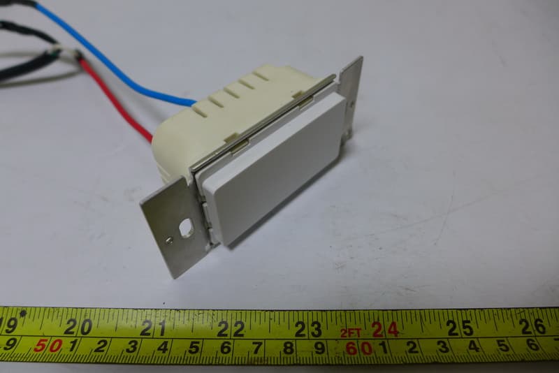
Z5N-7AM12
Dec 20, 2015Touch Switch
Equipment Class
DXX - Part 15 Low Power Communication Device Transmitter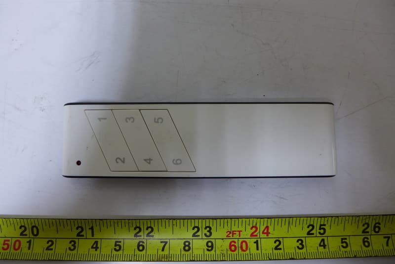
Z5N-RMC06
Dec 20, 2015Touch Switch
Equipment Class
DXX - Part 15 Low Power Communication Device Transmitter