Z5W-105008TRANSCEIVER
Damm Cellular Systems A/S
Click to zoom
Application Details
- Equipment Class
- TNB - Licensed Non-Broadcast Station Transmitter
- Date of Grant
- May 06, 2012
- Application Purpose
- Original Equipment
- Date of Application
- May 06, 2012
- Equipment Note
- TRANSCEIVER
- Frequency Range
- 862.00000000 - 869.00000000
- Company
- Damm Cellular Systems A/S
- Country
- Denmark
Documents & Files
Document Text
Text extracted from the exhibit documents filed with the FCC. Open a document above to read the original.
Users Manual
TetraFlex ® V7.5 US DRAFT version Manual version 1.01 27.01.2012 The information contained in this document is the property of Damm Cellular Systems A/S. This document is subject to copyright and shall not be published or reproduced, in whole or in part, without the written permission of Damm Cellular Systems A/S. © 2010 Damm Cellular Systems A/S. All rights reserved. Møllegade 68, DK-6400 Sønderborg, Denmark Phone: +45 74 42 35 00, Fax: +45 74 42 30 31, E-Mail: [email protected], Doc. No. Rev. Date DRAFT 1.01 2012-01-27 Damm Cellular Systems A/S, Denmark TetraFlex ® 7.5 Manual - Introduction TetraFlex® 7.5 Manual 2 http://www.damm.dk INTRODUCTION This manual is intended for installation and maintenance of BS4xx TetraFlex ® Base Station, including additional units, installation software, and how to configure the system for operational use. Remark: TetraFlex ® ver. 7.5 is not compatible with earlier versions! Please follow the update instructions or contact DAMM support if you have systems with older software versions. Doc. No. Rev. Date DRAFT 1.01 2012-01-27 Damm Cellular Systems A/S, Denmark TetraFlex ® 7.5 Manual - Introduction TetraFlex® 7.5 Manual 3 Indoor Base station models BS411 BS414 Max. 8 carriersMax. 4 carriers Max. 16 carriers Outdoorstation BS421 + SB 421 It is recommended that engineers doing the installation and configuration of a BS4xx have practical experience in installation of radio and computer systems, and have made themselves familiar with the BS4xx equipment through appropriate DAMM training courses and study of the content of this manual. This installation guide covers the installation of indoor as well as outdoor Base Stations as well as single units. Please skip the sections, which are not relevant for the actual case. Max. 4 carriers Doc. No. Rev. Date DRAFT 1.01 2012-01-27 Damm Cellular Systems A/S, Denmark TetraFlex ® 7.5 Manual - Introduction TetraFlex® 7.5 Manual 4 The manual is divided into more sections which may be printed separately. When doing so please print the Table of contents, introduction, update sheets and Index (all pages prior to page 1-1 and after page 4-x) and insert these in the printed section IMPORTANT: Updates / changes / important information related to the TetraFlex® system and software may be downloaded from the protected part of www.damm.dk Please check this URL for updated information before attempting to install or correct errors NOTE: Chapters marked with a indicate areas where special care must be taken to avoid personal injury or damage to the equipment. Before starting installation and configuration, please read the entire manual carefully. NOTE: It is the responsibility of the system owner / operator to ensure that only authorized service persons has access to the keys / inside circuits of the SB412 / BS4xx. NOTE: It is the responsibility of the system owner / operator to ensure that all local legislation, rules and regulations are complied with. The SB412 / BS4xx are protected by internal fuses. Always replace with fuses of equivalent value and type. General Warning This manual contains important safety and operational information. Please read and follow the instructions in this manual. Failure to do so could be hazardous and result in damage to your device. Changes and modifications to this device not expressly proved by DAMM could void the user’s authorization to operate this device FCC Regulations The DAMM developed device mentioned in this User Manual fulfills the below statements according to FCC/IC warning statements: This device complies with part 15 of the FCC Rules. Operation is subject to the following two conditions: (1) This device may not cause harmful interference, and (2) this device must accept any interference received, including interference that may cause undesired operation Doc. No. Rev. Date DRAFT 1.01 2012-01-27 Damm Cellular Systems A/S, Denmark TetraFlex ® 7.5 Manual - Reference documents TetraFlex® 7.5 Manual 5 RF Exposure The DAMM developed transmitting devices mentioned in this User Manual have the Nemko approval concerning “Maximum Permissible Exposure Calculations” which are the European limits for maximum permissible exposure defined in the document 1995/519/EC, Council Recommendation of 12. July 1999. The results are to be found in the Nemko Document 128948/5 in the appendix of this User Manual. Antennas The outside antenna connected to this device must be installed on an outdoor permanent structure with a separation of at least 20 feet from all persons during normal operation. Notice Do not modify any part of this device for any reason Do not place any combustible material near the transceiver Do not spray any liquid over the device Ensure that the power and antenna connections are securely made, using cables recommended and with excess capacity for the power being utilized. REFERENCE DOCUMENTS For detailed information’s regarding the TetraFlex ® release and features supported, please consult the documents listed below: No.: Document Title Document Contents 1 TetraFlex v7.5 System description.pdf * TetraFlex ® system overview 2 TetraOM_7.5.pdf TetraFlex ® OM manual 3 TetraFlex_RN_7.52_2011-09-30_02.pdf * TetraFlex ® system release note 4 TetraFlex 7.4x to 7.5 update.pdf Update guideline for ver.7.4x to 7.5 5 TetraFlex 7.5 BS41x redundant setup.pdf Redundancy sw setup guideline for BS41x *) These documents is a part of the TetraFlex ® release and placed in the C:\tetra\Active\Doc directory All documents can be found on www.damm.dk extranet. TETRAFLEX ® MANUAL BREAKDOWN Section Description Level Part 1 Physical hardware installation Tech Part 2 Software installation and configuration of software and system Tech Part 3 User manual intended for operators and non technical personnel User Part 4 Technical reference Tech Part 5 Hardware Units Ref. Tech Part 6 List of figures and Alphabetic index All Doc. No. Rev. Date DRAFT 1.01 2012-01-27 Damm Cellular Systems A/S, Denmark TetraFlex ® 7.5 Manual - …
Text truncated - open the document above for the full version.
Users Manual
Doc. No. Rev. Date DRAFT 1.01 2012-01-27 Damm Cellular Systems A/S, Denmark TetraFlex ® 7.5 Manual - BS421 Configuration TetraFlex® 7.5 Manual 2-71 2.6.4 Add a transceiver Adding a transceiver to a SB421 can be done either from the BSC-GUI or using OM command: BSC-GUI: Select the BSC tab and click on the TR’s configured menu and then add the TR. When clicking Ok the setting is saved. TetraOM: connect to the BSC Perform the following commands: F75 <Enter> This shows the configuration for TR 11-28 If the displayed message does not correspond to the actual number of TR, perform the command: F75/xx/ADD (F75/xx/REMOVE removes the TR again). xx =TR number e.g. 11. Doc. No. Rev. Date DRAFT 1.01 2012-01-27 Damm Cellular Systems A/S, Denmark TetraFlex ® 7.5 Manual - BS421 Configuration TetraFlex® 7.5 Manual 2-72 2.6.4.1 Diversity configuration Two TR421 may be used without the RF coaxial connection between them. In this case the system will behave normally as a 2 carrier system, but will NOT support diversity. When using diversity set-up (Standard configuration), the RF coaxial connection must be installed and RX-B input (6dB pre gain) must be set This configuration also applies to the 4 carrier configuration, where the carriers are defined as two 2 carrier systems. 2.6.4.2 RX-B setting (Diversity) in TetraOM: 24 Display setting 24+ Select RX-B input Cascaded (Standard setting) 24- Deselect RX-B input Cascaded NOTE: This must be configured in both BS421 2.6.4.3 3 And 4 carrier operation NOTE: Operation with 3 and 4 carriers with redundant BSC require a change to the HW of the BS421 and the SB421 (See the SB421 section for details) if the HW version stipulated on the serial number label is v1. HW version v2 and forth has the possibility to change the setting via the TetraOM program. This change is required to ensure correct BSC handover and synchronization of the carriers The change cannot be made in the field. The system must be ordered for 4 carrier operation or the units may be returned to DAMM for modifications. NOTE: For change in the field (trained staff only), please order a change kit from DAMM This kit includes a manual dealing with this issue and the necessary hardware, jumpers, screws, markings etc. For a 4 carrier system, 2 of the BS421 is marked “MASTER” and 2 are marked “SLAVE” One master and one slave are to be connected to each SB421, the master being TR1/TR3 and the slave TR2/TR4. NOTE: A GPS antenna should at least be connected to TR1 and TR3 2.6.4.4 Synchronization The TETRA Base Station TR's need to be time synchronized to operate correctly. Most important, all TR's in a radio cell shall be time synchronized to ensure correct timing for the mobiles, when switching from the control channel to a traffic channel on another TR. For a multi-cell systems, all radio cells are also recommended to be time synchronized to enable use of seamless handover (cell re-selection). Doc. No. Rev. Date DRAFT 1.01 2012-01-27 Damm Cellular Systems A/S, Denmark TetraFlex ® 7.5 Manual - BS421 Configuration TetraFlex® 7.5 Manual 2-73 The Damm BS system has a flexible system to provide synchronization between individual Transceivers. Build-in GPS Receivers give absolute time synchronization to the radio cells. External Inputs can also be marked as Primary Sync. References. When a BS is Network locked, automatic frequency correction of the Master Oscillator (RX and TX carrier frequencies) is provided, and Seamless Handover to other Network Synchronized Cells is activated. The BS can be setup to run as either Sync Master 0 to 4 or Slave. The Masters shall preferably be provided with GPS antennas or an External Primary Sync source. The remaining BS's shall be setup as Slave and does not need a GPS antenna. The BS421 is provided with one External 1PPS (1 Pulse Per Second) output and two external 1PPS inputs. The Slaves shall receive external 1PPS inputs connected to Masters. In addition to the hardware 1PPS, sync messages are send every second on IP from the Masters to attached BS's. A Master will indicate Master Mode, if: 1) Synchronized to the internal GPS RX or 2) Synchronized to an External Input marked as Primary and indicating Master Mode The priority can be changed with OM command 72/MASTER/c (c = 0-4 or S) Master 0 priority: 1) Int. GPS RX 2) Ext. Master 1, Master Mode 3) Ext. Master 2, Master Mode 4) Ext. Master 3, Master Mode 5) Ext. Master 4, Master Mode 6) Ext. Master 1, Resync-only 7) Ext. Master 2, Resync-only 8) Ext. Master 3, Resync-only 9) Ext. Master 4, Resync-only 10) Int. Free-Run Master 1 priority: 1) Ext. Master 0, Master Mode 2) Int. GPS RX 3) Ext. Master 2, Master Mode 4) Ext. Master 3, Master Mode 5) Ext. Master 4, Master Mode 6) Ext. Master 0 7) Ext. Master 2, Resync-only 8) Ext. Master 3, Resync-only 9) Ext. Master 4, Resync-only 10) Int. Free-Run Doc. No. Rev. Date DRAFT 1.01 2012-01-27 Damm Cellular Systems A/S, Denmark TetraFlex ® 7.5 Manual - BS421 Configuration TetraFlex® 7.5 Manual 2-74 Master 2 priority: 1) Ext. Master 0, Master Mode 2) Ext. Master 1, Master Mode 3) Int. GPS RX 4) Ext. Master 3, Master Mode 5) Ext. Master 4, Master Mode 6) Ext. Master 0 7) Ext. Master 1 8) Ext. Master 3, Resync-only 9) Ext. Master 4, Resync-only 10) Int. Free-Run Master 3 priority: 1) Ext. Master 0, Master Mode 2) Ext. Master 1, Master Mode 3) Ext. Master 2, Master Mode 4) Int. GPS RX 5) Ext. Master 4, Master Mode 6) Ext. Master 0 7) Ext. Master 1 8) Ext. Master 2 9) Ext. Master 4, Resync-only 10) Int. Free-Run Master 4 priority: 1) Ext. Master 0, Master Mode 2) Ext. Master 1, Master Mode 3) Ext. Master 2, Master Mode 4) Ext. Master 3, Master Mode 5) Int. GPS RX 6) Ext. Master 0 7) Ext. Master 1 8) Ext. Master 2 9) Ext. Master 3 10) Int. Free-Run Slave priority: 1) Ext. Master 0, Master Mode 2) Ext. Master 1, Master Mode 3) Ext. Master 2, Master Mode 4) Ext. Master 3, Master Mode 5) Ext. Master 4, Master Mode 6) Ext. Master 0 7) Ext. Master 1 8) Ext. Master 2 9) Ext. Master 3 10) Ext. Maste…
Text truncated - open the document above for the full version.
Cover Letter(s)
TCB FCC Approvals FCB Industry Canada Approval NB Notified Body for Europe 849 NW State Road 45 P. O. Box 370 Newberry, Florida 32669 USA Telephone (352) 472-5500 (888) 472-2424 FAX (352) 472-2030 email: [email protected] February 13, 2012 Federal Communications Commission Authorization and Evaluation Division 7435 Oakland Mills Road Columbia, MD 21046 Ref: Confidentiality request regarding application for Certification for FCC ID: Z5W-105008 To Whom It May Concern: Pursuant to Sections 0.457 and 0.459 of the Commission’s Rules, Damm Cellular Systems A/S hereby requests confidential treatment of information accompanying this application as outlined below: Exhibit Type File Name DAMM Description Circuit Description TetraFlex V7 5 System Description (1 2).pdf Circuit Description Tuning Procedure Tuning Procedure.pdf Tuning Procedure Block Diagram Bs421_Block.pdf Block Diagram Parts List D105008-LST.pdf Parts List D205008-LST.pdf Schematic Diagram D305001-SCM.pdf Main Board for BS421 Parts List D305001-LST.pdf Parts List D105084-LST.pdf System Connector for BS421 Parts List D305078-LST.pdf Filter for BS421 805-825 MHz 850-870 MHz Schematic Diagram D305018-SCM.pdf RX Board for BS421 805-825 MHz Parts List D305018-LST.pdf Schematic Diagram D30502x-SCM.pdf Exciter for BS421 850-870 MHz Parts List D305028-LST.pdf Schematic Diagram D305058-SCM.pdf RFTL conv FOR BS421 805-935 Parts List D305058-LST.pdf Schematic Diagram D305038-SCM.pdf PA for BS421 850-870 MHz Parts List D305038-LST.pdf Schematic Diagram D-30504X-SCM.pdf Power Detector for BS421 850-870 MHz Parts List D305048-LST.pdf TCB FCC Approvals FCB Industry Canada Approval NB Notified Body for Europe 849 NW State Road 45 P. O. Box 370 Newberry, Florida 32669 USA Telephone (352) 472-5500 (888) 472-2424 FAX (352) 472-2030 email: [email protected] The above materials contain trade secrets and proprietary information not customarily released to the public. The public disclosure of these materials may be harmful to Damm Cellular Systems A/S and provide unjustified benefits to its competitors. Damm Cellular Systems A/S understands that pursuant to Section 0.457 of the Rules, disclosure of this application and all accompanying documentation will not be made public before the date of the Grant for this application. Pursuant to DA04-1705 June 15, 2004, of the Commission’s public notice, we also request temporary confidential treatment up to 180 days of information accompanying this application as outlined below: Exhibit Type File Name External Photos External photos.pdf Internal Photos Internal photos.pdf User Manual TetraFlexV7.5_User_Manual_1.01_US_Draft-1.pdf TetraFlexV7.5_User_Manual_1.01_US_Draft-2.pdf TetraFlexV7.5_User_Manual_1.01_US_Draft-3.pdf TetraFlexV7.5_User_Manual_1.01_US_Draft-4.pdf Test Set Up Photos Test Set Up Photos.pdf Sincerely, Mario R. de Aranzeta
Cover Letter(s)
Generated by CamScanner from intsig.com
External Photos
APPLICANT: DAMM CELLULAR SYTEMS A/S FCC ID: Z5W-105008 IC: 10159A-105008 MODEL: BS421 Base Station 805-825/850-870 MHz EXTERNAL PHOTOS
Internal Photos
APPLICANT: DAMM CELLULAR SYTEMS A/S FCC ID: Z5W-105008 IC: 10159A-105008 MODEL: BS421 Base Station 805-825/850-870 MHz INTERNAL PHOTOS MAIN BOARD FOR BS421 RX BOARD FOR BS421 805-825 MHz EXCITER FOR BS421 850-870 MHz PA FOR BS421 850-870 MHz POWER DETECTOR FOR BS421 850-870 MHz RFTL CONV FOR BS421 805-935 MHZ FILTER FOR BS421
Test Report
FCC PART 90 AND IC RSS-119, RSS-GEN TEST REPORT APPLICANT DAMM CELLULAR SYSTEMS A/S MOLLEGADE 68 6400 SONDERBORG DENMARK FCC ID Z5W105008 IC CERTIFICATION 10159A-105008 MODEL NUMBER BS421 Base Station 805-825/851-869 MHz PRODUCT DESCRIPTION TRANSMITTER DATE SAMPLE RECEIVED 12/12/2011 DATE TESTED 3/23/2012 TESTED BY Joe Scoglio APPROVED BY Mario R. de Aranzeta TIMCO REPORT NO. 2915AT11TestReport.doc TEST RESULTS PASS FAIL THE ATTACHED REPORT SHALL NOT BE REPRODUCED EXCEPT IN FULL WITHOUT THE WRITTEN APPROVAL OF TIMCO ENGINEERING, INC. TABLE OF CONTENTS 849 NW STATE ROAD 45 NEWBERRY, FL 32669 USA PH: 888.472.2424 OR 352.472.5500 FAX: 352.472.2030 EMAIL: [email protected] HTTP: //WWW.TIMCOENGR.COM Certificate # 0955-01 Applicant: DAMM CELLULAR SYSTEMS A/S FCC ID: Z5W-105008 IC CERT #: 10159A-105008 Report: D\DAMM\2915AT11\2915AT11TestReport.doc Page 2 of 21 TABLE OF CONTENTS GENERAL REMARKS ......................................................................................................... 3 GENERAL INFORMATION .................................................................................................. 4 TEST PROCEDURES ......................................................................................................... 5 RF POWER OUTPUT .......................................................................................................... 6 MODULATION CHARACTERISTICS .................................................................................... 7 AUDIO FREQUENCY RESPONSE ....................................................................................... 8 AUDIO LOW PASS FILTER ................................................................................................. 8 AUDIO INPUT VERSUS MODULATION ............................................................................... 8 OCCUPIED BANDWIDTH ................................................................................................... 9 SPURIOUS EMISSIONS AT ANTENNA TERMINALS (CONDUCTED) ................................... 15 FIELD STRENGTH OF SPURIOUS EMISSIONS ................................................................. 18 FREQUENCY STABILITY .................................................................................................. 20 EMC EQUIPMENT LIST ................................................................................................... 21 Applicant: DAMM CELLULAR SYSTEMS A/S FCC ID: Z5W-105008 IC CERT #: 10159A-105008 Report: D\DAMM\2915AT11\2915AT11TestReport.doc Page 3 of 21 GENERAL REMARKS The attached report shall not be reproduced except in full without the written permission of Timco Engineering Inc. The test results relate only to the items tested. Summary The device under test does: fulfill the general approval requirements as identified in this test report not fulfill the general approval requirements as identified in this test report Attestations This equipment has been tested in accordance with the standards identified in this test report. To the best of my knowledge and belief, these tests were performed using the measurement procedures described in this report. All instrumentation and accessories used to test products for compliance to the indicated standards are calibrated regularly in accordance with ISO 17025: 2005 requirements. Testing Certificate # 0955-01 I attest that the necessary measurements were made, under my supervision, at: Timco Engineering Inc. 849 NW State Road 45 Newberry, Fl 32669 Authorized Signatory Name: Mario de Aranzeta C.E.T. Compliance Engineer/ Lab. Supervisor Date: March 23, 2012 Applicant: DAMM CELLULAR SYSTEMS A/S FCC ID: Z5W-105008 IC CERT #: 10159A-105008 Report: D\DAMM\2915AT11\2915AT11TestReport.doc Page 4 of 21 GENERAL INFORMATION DUT Specification DUT Description DOOR SYSTEM - TRANSMITTER FCC ID Z5W-105008 IC Certification 10159A-105008 Model Number BS421 Base Station 805-825/851-869 MHz Serial Number N/A Operating Frequency 851-869 MHz Test Frequencies 856.0, 863.0, 869.0 MHz Type of Emission 21K0D1W, 21K0D1D, 21K0D1E, & 21K0D7W 20K0D1W, 20K0D1D, 20K0D1E, & 20K0D7W Modulation 0.35 TETRA, 0.20 modified TETRA DUT Power Source 110–120Vac/50– 60Hz DC Power 12V Battery Operated Exclusively Test Item Prototype Pre-Production Production Type of Equipment Fixed Mobile Portable Test Conditions The temperature was 26ºC with a relative humidity of 50%. Modification to the DUT None Test Exercise The DUT was placed in continuous transmit mode. Applicable Standards ANSI/TIA 603-C:2004, FCC CFR 47 Part 90, IC RSS- 119, RSS-GEN Test Facility Timco Engineering Inc. at 849 NW State Road 45 Newberry, FL 32669 USA. Applicant: DAMM CELLULAR SYSTEMS A/S FCC ID: Z5W-105008 IC CERT #: 10159A-105008 Report: D\DAMM\2915AT11\2915AT11TestReport.doc Page 5 of 21 TEST PROCEDURES Power Line Conducted Interference: The procedure used was ANSI/TIA 603-C:2004 using a 50uH LISN. Both lines were observed with the DUT transmitting. The bandwidth of the spectrum analyzer was 10 kHz with an appropriate sweep speed. Bandwidth 20 dB: The measurements were made with the spectrum analyzer's resolution bandwidth (RBW) = 1 MHz and the video bandwidth (VBW) = 3 MHz and the span set as shown on plot. Power Output: The RF power output was measured at the antenna feed point using a peak power meter. Antenna Conducted Emissions: The RBW = 100 kHz, VBW = 300 kHz and the span set to 10.0 MHz and the spectrum was scanned from 30 MHz to the 10 th harmonic of the fundamental. Above 1 GHz the resolution bandwidth was 1 MHz and the VBW = 3 MHz and the span to 50 MHz. Radiation Interference: The test procedure used was ANSI/TIA 603-C:2004 using an Agilent spectrum receiver with pre-selector. The bandwidth (RBW) of the spectrum receiver was 100 kHz up to 1 GHz and 1 MHz above 1 GHz with an appropriate sweep speed. The VBW above 1 GHz was 3 MHz. The analyzer was calibrated in dB above a micro volt at the output of the antenna. Applicant: DAMM CELLULAR SYSTEMS A/S FCC ID: Z5…
Text truncated - open the document above for the full version.
Test Setup Photos
APPLICANT: DAMM CELLULAR YSTEMS A/S FCC ID: Z5W-105008 EXTERNAL PHOTOS RADIATED EMISSIONS TEST SET UP POWERLINE CONDUCTED EMISSIONS TEST SET UP
Contact Information
Applicant
Tommy Trip(Group CEO)
Test Firm
Timco Engineering, Inc.Bruno Clavier
Technical Specifications
| # | Rule Parts | Frequency Range | Power Output | Emission | Tolerance |
|---|---|---|---|---|---|
| 4 | 9 | 862 MHz - 869 MHz | 1 W | NOTE 1 | 0.014 ppm |
Other Applications from Damm Cellular Systems A/S

Z5W-10520141
Jul 23, 2020400 MHz band cellular base station
Equipment Class
TNB - Licensed Non-Broadcast Station Transmitter
Z5W-10520111
May 19, 2020150 MHz band cellular base station
Equipment Class
TNB - Licensed Non-Broadcast Station Transmitter
Z5W-10520101
May 13, 202070 MHz band cellular base station
Equipment Class
TNB - Licensed Non-Broadcast Station Transmitter
Z5W-105003
Mar 06, 2013Base Station
Equipment Class
TNB - Licensed Non-Broadcast Station Transmitter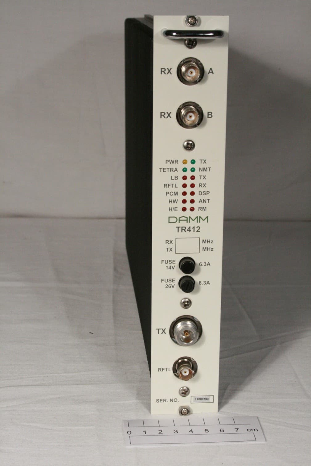
Z5W-104013
Mar 06, 2013Door System Transmitter
Equipment Class
TNB - Licensed Non-Broadcast Station Transmitter