Z64-CC3100MODR1Radio Module
Texas Instruments Incorporated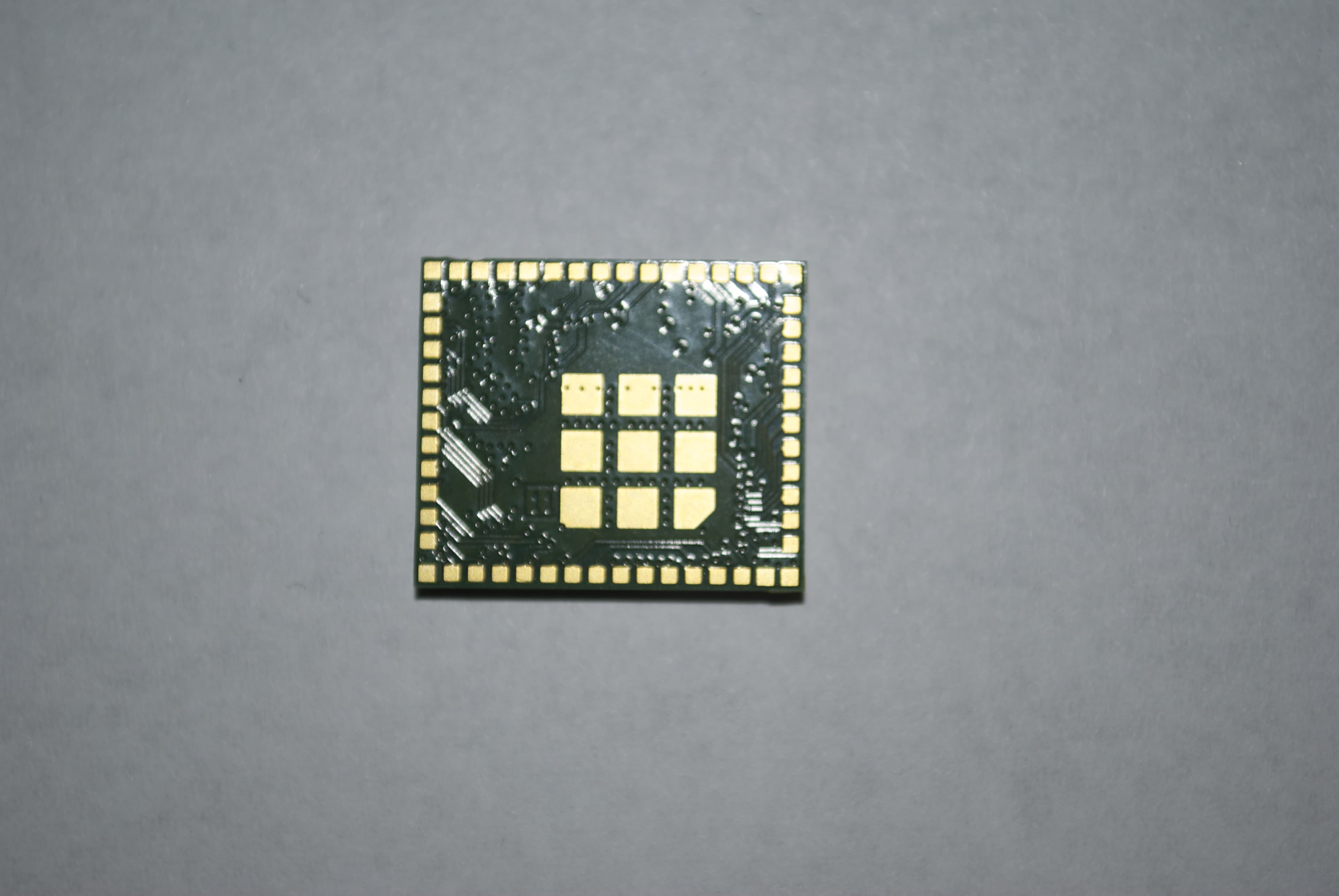
Click to zoom
Application Details
- Equipment Class
- DTS - Digital Transmission System
- Date of Grant
- Oct 08, 2014
- Application Purpose
- Original Equipment
- Date of Application
- Oct 08, 2014
- Equipment Note
- Radio Module
- Frequency Range
- 2412.00000000 - 2462.00000000
- Country
- United States
Documents & Files
Document Text
Text extracted from the exhibit documents filed with the FCC. Open a document above to read the original.
Users Manual
EVM User’s Guide TI Confidential – Strictly Private 2 CC3100MOD Boosterpack™ (Evaluation board) User Guide ECS Applications Table 1. Document Change Log Date (Version) Author Approved by Description Initial Release EVM User’s Guide TI Confidential – Strictly Private 3 Contents Getting Started .......................................................................................................................... 4 1 Introduction ....................................................................................................................... 4 1.1 CC3100MOD BOOST 4 1.2 CC3100MOD Module 4 2 Hardware description ........................................................................................................ 5 2.1 Block Diagram 6 2.2 Hardware Features of the evaluation board 6 2.3 Connector and jumper descriptions 7 2.3.1 Push buttons and LEDs 7 2.3.2 Jumper settings 7 2.3.3 2x20 pin connector assignment 9 2.4 Power 10 3 Connecting to the PC using EMUBOOST ...................................................................... 11 3.1 CC31XXEMUBOOST 11 3.2 Mating the boards 12 3.3 Jumper settings on the EMUBOOST 12 4 Connecting to a Launchpad .......................................................................................... 14 4.1 Launchpad current limitation 14 5 PCB information .............................................................................................................. 15 5.1 Layout information 15 5.2 Antenna pattern 17 5.3 Schematics 18 5.4 Bill of materials 20 EVM User’s Guide TI Confidential – Strictly Private 4 Getting Started 1 Introduction 1.1 CC3100MOD BOOST Introducing the CC3100MOD Booster pack compatible with all TI Launchpads for adding WIFI capability to embedded systems. The CC3100MODBOOST Booster Pack is an easy-to-use evaluation module for the CC3100 WIFI device. It contains everything needed to start developing a WIFI solution on TI Launchpad. This board is also designed to interface with another board named CC3100EMUBOOST (FTDI based Emulation and debug board) to provide an interface to the PC for development using SimpleLink™ Studio (TI provided application and source code to develop WIFI based software on a PC) The CC3100MOD module integrates the complete RF, digital baseband, and power management needed to provide WIFI access to any embedded system using a 8,16 ot 32 bit Microcontrollers. Rapid prototyping is a snap thanks to the 40-pin headers and a wide variety of Launchpads available. These connectors provide stackability to ensure that other booster-packs like Audio, LCD, sensors etc. can be mounted on top or bottom of this booster-pack. 1.2 CC3100MOD Module The CC3100MOD module is a second-generation SimpleLink™ Wi-Fi self-contained network processor module that dramatically simplifies the implementation of Internet connectivity. The CC3100MOD module is an ideal solution for embedded applications using low-cost and low-power microcontrollers with reduced board space and faster development times. Fully integrated module with serial flash, Crystal and RF filter. Only needs power supply and a serial interface to operate. 802.11 b/g/n Station With Fully Integrated Radio, Baseband, and MAC 802.11 Transceiver Mode IPv4 TCP/IP Stack 8 Simultaneous TCP, UDP, or RAW Sockets ARP, ICMP, DHCP, DNS, mDNS TLS 1.2/SSL 3.0 With On-Chip Accelerators Throughput UDP: 16 Mbps, TCP: 12 Mbps Interfaces With 8-, 16-, and 32-bit MCU over an SPI Interface with up to 24-MHz Clock EVM User’s Guide TI Confidential – Strictly Private 5 2 Hardware description nHIB nRESET (Optional) Micro USB Conn (Power only) 3.3V Dc/Dc CC3100 Chip Antenna OOB U.FL Conn PWR SEL 20 pin LP Connector 20 pin LP Connector CC3100MOD Figure 1 : CC3100MODBOOST evaluation board with the CC3100MOD Module EVM User’s Guide TI Confidential – Strictly Private 6 2.1 Block Diagram CC3100MOD 2x20 headers Micro USB 3.3V LDO Chip Antenna Jumper Murata Conn Diode Mux 5V 5V 3.3V Current Meas J6 J8 U.FL Conn Vcc LED Indicators SPI/UART/GPIO Push Buttons Figure 2 : CC3100MODBOOST Block diagram 2.2 Hardware Features of the evaluation board • CC3100MOD module with fully integrated solution. 2x20 pin stackable connectors • On-board chip antenna with option for U.FL based conducted testing. • Power from on-board LDO using USB OR 3.3V from MCU Launchpad • Push buttons (3x), LEDs (2x) • Jumper for current measurement with provision to mount 0.1R resistor for measurement with voltmeter • 2 Layer PCB with 6mil spacing and track width. EVM User’s Guide TI Confidential – Strictly Private 7 2.3 Connector and jumper descriptions 2.3.1 Push buttons and LEDs Push buttons Reference Usage Comments SW1 OOB Demo This is used as an input for the OOB demo. SW2 RESET The use of this pin is optional. This is used to reset the CC3100 device which can also be accomplished using the nHIB button. The RESET completely erases the CC3100 RAM including the time. LEDs Reference Colour Usage Comments D5 RED PWR Indication Glows when the 3.3V power is provided to the board D1 Yellow nRESET This LED is used to indicate the stated of nRESET pin. If this LED is glowing, the device is functional. D6 Green nHIB This LED indicates the stated of nHIB pin. When the LED is OFF, the device is in hibernate state. 2.3.2 Jumper settings Reference Usage Comments J21 USB connector For powering the booster pack when mated with a Launchpad. This is mandatory to use when using “Z” devices. For e.g. CC3100HZ J8 Power selection Choose the power supply from the EVM User’s Guide TI Confidential – Strictly Private 8 Lauchpad or the on-board USB. J8 (1-2) power from MCU Launchpad J8 (2-3) power from on-board USB using 3.3V LDO J6 Current measurement For Hibernate and LPDS currents connect a ammeter across J26 : Range (< 500uA) For Active current, mount a 0.1 Ohm resistor on R42 and measure the voltage across the 0.1 Ohm resistor using a voltmeter. Range (< 50mV peak-peak) J5 OOB Demo Closed : GPIO_12 is hard pulled to Vcc Open : GPIO…
Text truncated - open the document above for the full version.
ID Label/Location Info
Position
Operational Description
The CC3100MODR1 is the second-generation series of modules in the SimpleLink family and consists of a Wi-Fi network processor and a power- management subsystem. CC3100MOD minimizes host microcontroller unit (MCU) software requirements and is the ideal solution for embedded applications using any on-board MCU with or without an RTOS. The module comes integrated with all required components including flash, clocks, and RF filter for easy hardware integration and quick time-to- market. The Wi-Fi network processor subsystem contains a dedicated ARM® Cortex®-M3 MCU to completely offload the host MCU. This subsystem includes 802.11 b/g/n radio, baseband, and medium access control with a powerful crypto engine for fast, secured Wi-Fi, and internet connections with 256-bit encryption. The CC3100MOD supports station, access point, and Wi-Fi Direct modes. The CC3100MOD also supports WPA2 personal and enterprise security and WPS 2.0. The Wi-Fi network processor includes an embedded IPv4 TCP/IP stack. The power-management subsystem includes an integrated DC-DC converter with support for a wide range of supply voltages. This subsystem enables low-power consumption modes such as hibernate with RTC mode, which requires less than 18 μA of current. The antenna is external to the module and it is a Taiyo Yuden 2.4GHz Multilayer RadiEdge antenna (MN: AH 316M245001) with a peak gain of 1.9dBi.
RF Exposure Info
Prediction of MPE limit at a given distance Equation from page 18 of OET Bulletin 65, Edition 97-01 where:S = power density P = power input to the antenna G = power gain of the antenna in the direction of interest relative to an isotropic radiator R = distance to the center of radiation of the antenna Maximum peak output power at device output terminal:14.64dBm Cable and Jumper loss:0.0dB Maximum peak output power at antenna input terminal:14.64dBm 29.10717118mW Single Antenna gain (typical):1.9dBi Number of Antennae:1 Total Antenna gain (typical):1.9dBi 1.548816619(numeric) Prediction distance:20cm Prediction frequency:2437MHz MPE limit for uncontrolled exposure at prediction frequency:1mW/cm 2 Power density at prediction frequency:0.008969 mW/cm 2 0.089687W/m 2 Tx On time:1.000000ms Tx period time:1.000000ms Average Factor:100.000000% Average Power density at prediction frequency:0.089687W/m 2 Maximum allowable antenna gain:22.37269855dBi Margin of Compliance:20.47269855 dB 2 4R PG S π =
Test Report
www.nemko.com Nemko Canada Inc., a testing laboratory, is accredited by the Standards Council of Canada. The tests included in this report are within the scope of this accreditation FCC 15.247 and RSS-210 A8.docx; Date: May 2013 SCC Accredited LAB LAB Accrédité CCN TM ONE WORLDOURAPPROVAL Test report 264561-3TRFWL Date of issue: September 25, 2014 Applicant: Texas Instruments Inc. Product: CC3100 Booster-pack Model: CC3100MODR11MAMOB FCC ID: IC Registration number: Z64-CC3100MODR1 451I-CC3100MODR1 Specifications: FCC 47 CFR Part 15 Subpart C, §15.247 Operation in the 902–928 MHz, 2400–2483.5 MHz, 5725–5850 MHz RSS-210, Issue 8, December 2010, Annex 8 Frequency Hopping and Digital Modulation Systems Operating in the 902–928 MHz, 2400–2483.5 MHz, and 5725–5850 MHz Bands Report reference ID: 264561-3TRFWL Page 2 of 33 Test location Company name: Nemko Canada Inc. Address: 303 River Road City: Ottawa Province: Ontario Postal code: K1V 1H2 Country: Canada Telephone: +1 613 737 9680 Facsimile: +1 613 737 9691 Toll free: +1 800 563 6336 Website: www.nemko.com Site number: FCC: 176392; IC: 2040A-4 (3 m semi anechoic chamber) Tested by: Kevin Rose, Wireless/EMC Specialist Reviewed by: Andrey Adelberg, Senior Wireless/EMC Specialist Date: September 25, 2014 Signature: Limits of responsibility Note that the results contained in this report relate only to the items tested and were obtained in the period between the date of initial receipt of samples and the date of issue of the report. This test report has been completed in accordance with the requirements of ISO/IEC 17025. All results contain in this report are within Nemko Canada’s ISO/IEC 17025 accreditation. Copyright notification Nemko Canada Inc. authorizes the applicant to reproduce this report provided it is reproduced in its entirety and for use by the company’s employees only. Any use which a third party makes of this report, or any reliance on or decisions to be made based on it, are the responsibility of such third parties. Nemko Canada Inc. accepts no responsibility for damages, if any, suffered by any third party as a result of decisions made or actions based on this report. © Nemko Canada Inc. Report reference ID: 264561-3TRFWL Page 3 of 33 Table of contents Table of contents .......................................................................................................................................................................................................... 3 Section 1. Report summary ................................................................................................................................................................................. 4 1.1 Applicant and manufacturer .................................................................................................................................................................................... 4 1.2 Test specifications .................................................................................................................................................................................................... 4 1.3 Test methods ............................................................................................................................................................................................................ 4 1.4 Statement of compliance ......................................................................................................................................................................................... 4 1.5 Exclusions ................................................................................................................................................................................................................. 4 1.6 Test report revision history ...................................................................................................................................................................................... 4 Section 2. Summary of test results ....................................................................................................................................................................... 5 2.1 FCC Part 15 Subpart C, general requirements test results ........................................................................................................................................ 5 2.2 FCC Part 15 Subpart C, intentional radiators test results.......................................................................................................................................... 5 2.3 IC RSS-GEN, Issue 3, test results ............................................................................................................................................................................... 5 2.4 IC RSS-210, Issue 8, test results ................................................................................................................................................................................ 6 Section 3. Equipment under test (EUT) details ..................................................................................................................................................... 7 3.1 Sample information .................................................................................................................................................................................................. 7 3.2 EUT information ....................................................................................................................................................................................................... 7 3.3 Technical information .............................................................................................................................................................................................. 7 3.4 Product description and theory of operation ...............................................…
Text truncated - open the document above for the full version.
Test Setup Photos
www.nemko.com Nemko Canada Inc., a testing laboratory, is accredited by the Standards Council of Canada. The tests included in this report are within the scope of this accreditation setup photos.docx; Date: May 2013 SCC Accredited LAB LAB Accrédité CCN TM ONE WORLDOURAPPROVAL Setup photos 264561-3RADWL Date of issue: September 25, 2014 Applicant: Texas Instruments Inc. Product: CC3200 LaunchPad Model: Model: CC3200MODR1M2AMOB CC3200MODR1M2AMOB FCC ID: FCC ID: Z64-CC3200MODR1 Z64-CC3100MODR1 Z64-CC3200MODR1 Z64-CC3100MODR1 Section 1: Internal photos Report reference ID: 264561-2RADWL Page 2 of 2 Section 1. Internal photos 1.1 Top general view
Contact Information
Applicant
Marian Kost(Product Line Manager, Connectivity)
Test Firm
Nemko Canada Inc. (Ottawa)Charles Neal
Technical Specifications
| # | Rule Parts | Frequency Range | Power Output |
|---|---|---|---|
| 1 | 15C | 2.41 GHz - 2.46 GHz | 29.00 mW |
Other Applications from Texas Instruments Incorporated
Z64-CC33SBMOD
Jul 17, 2025802.11 b/g/n/ax WLAN + BLE Radio Module
Equipment Class
DTS - Digital Transmission System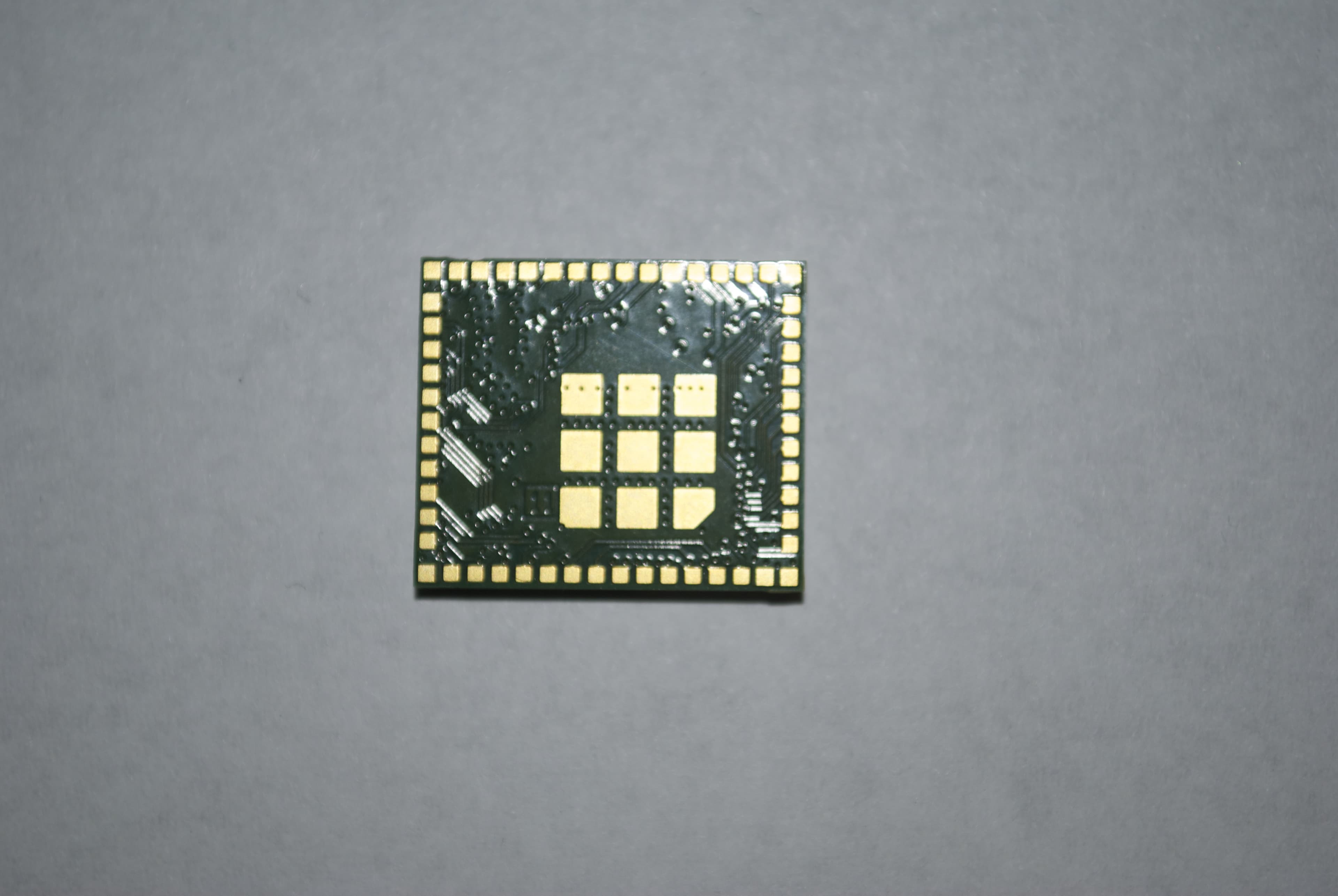
Z64-CC3200MODR1
Oct 08, 2014Radio Module
Equipment Class
DTS - Digital Transmission System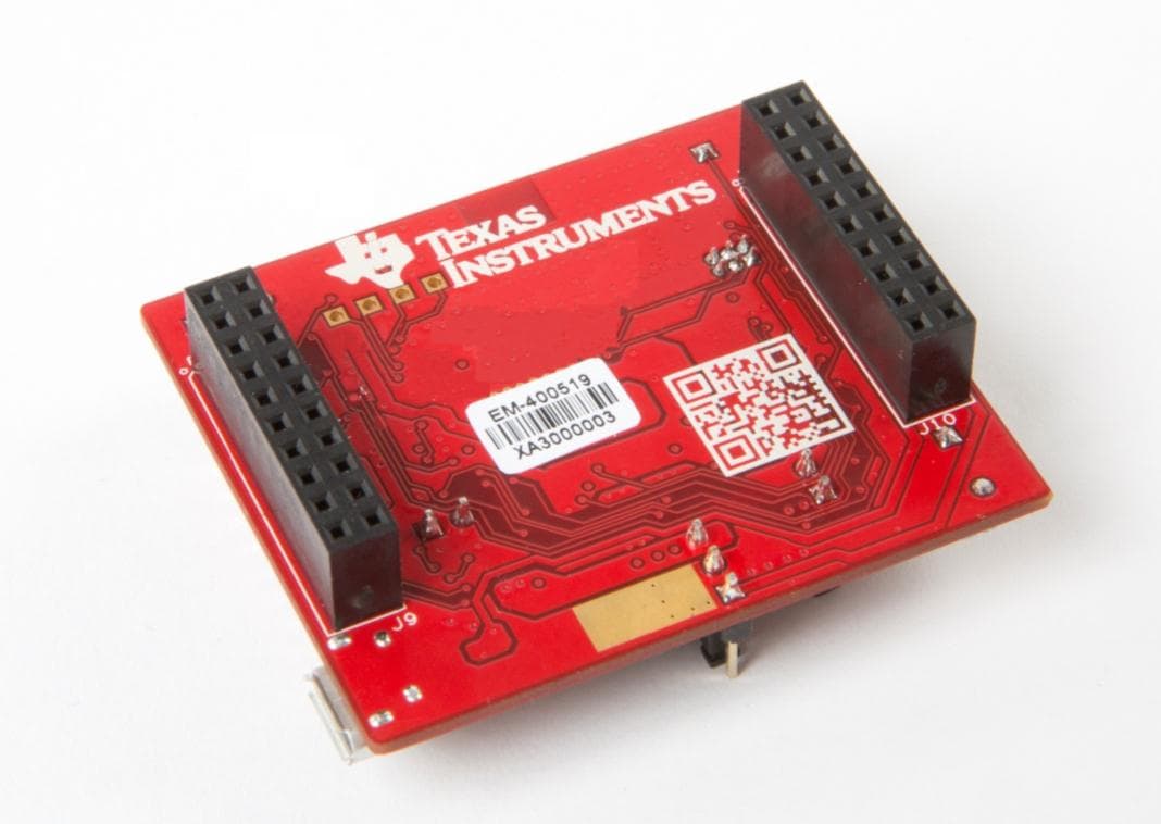
Z64-CC3100KITA
May 06, 2014Evaluation board
Equipment Class
DTS - Digital Transmission System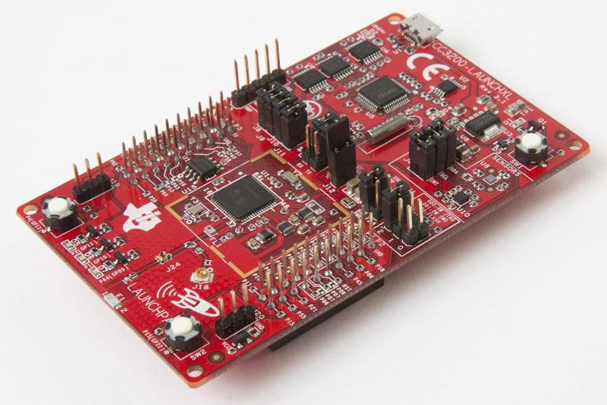
Z64-CC3200KITA
May 06, 2014Evaluation board
Equipment Class
DTS - Digital Transmission System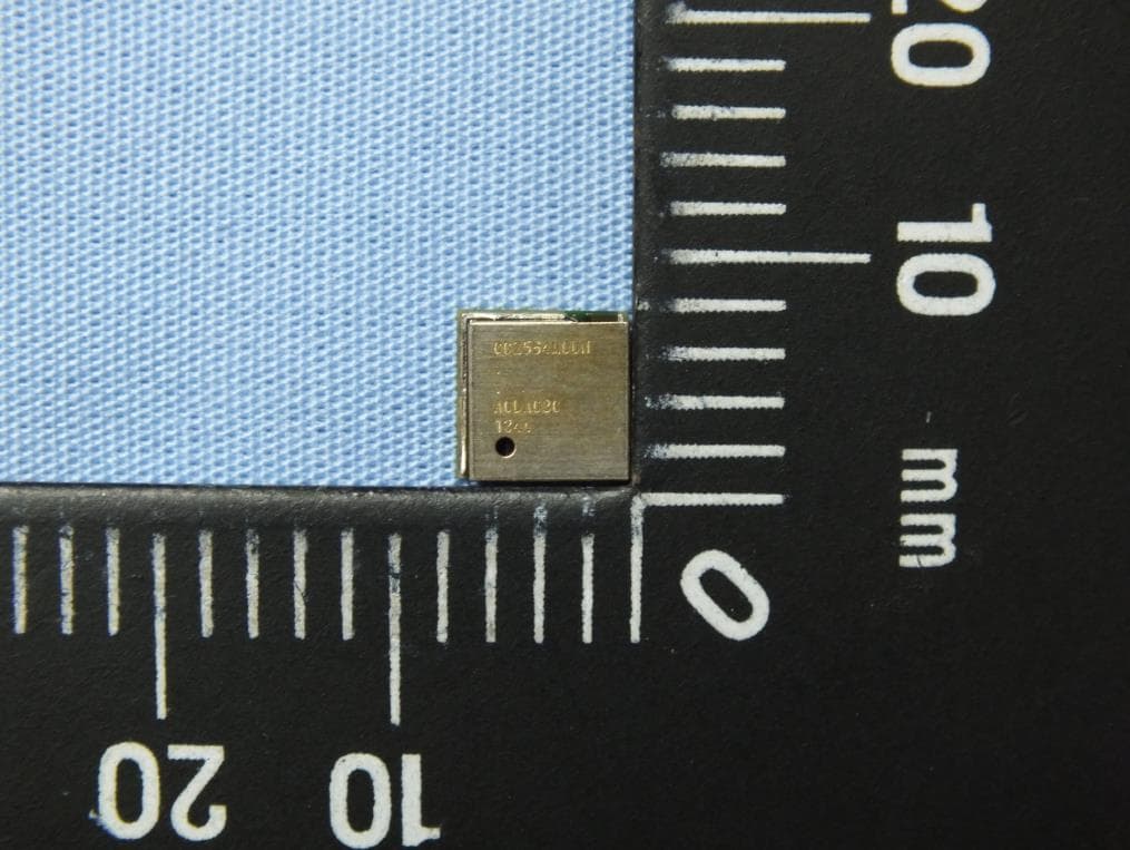
Z64-2564N
Mar 31, 2014CC2564 Bluetooth HCI Module
Equipment Class
DTS - Digital Transmission System