Z8H89FT0005Dual Channel OFDM MIMO Station
Cambium Networks Inc.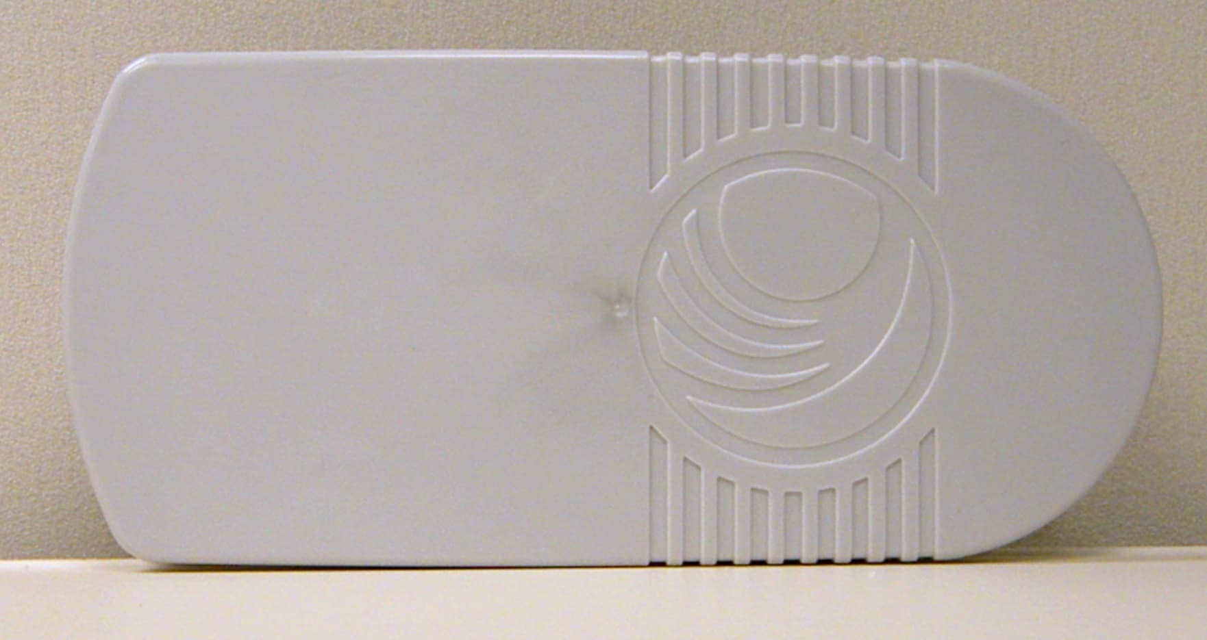
Click to zoom
Application Details
- Equipment Class
- DTS - Digital Transmission System
- Date of Grant
- Sep 05, 2013
- Application Purpose
- Original Equipment
- Date of Application
- Aug 25, 2013
- Equipment Note
- Dual Channel OFDM MIMO Station
- Frequency Range
- 5750.00000000 - 5825.00000000
- Company
- Cambium Networks Inc.
- Country
- United States
Documents & Files
Document Text
Text extracted from the exhibit documents filed with the FCC. Open a document above to read the original.
Users Manual
Cambium ePMP Quick Start Guide System Release Beta ePMP Series Model Numbers This Quick Start Guide may be referenced for the following Cambium ePMP equipment: Model Description N000900L001A ePMP Pwr Supply for GPS Radio - no cord (spare) N000900L002A ePMP Pwr Supply for non-GPS Radio - no cord (spare) C050900A011A ePMP GPS, Conn - 5 GHz - no power cord C058900A112A ePMP GPS, Conn - 5 GHz - US power cord - FCC version C050900A021A ePMP Conn - 5 GHz - no power cord C058900A122A ePMP Conn - 5 GHz - US power cord - FCC version C050900C031A ePMP Integ(16dBi) - 5 GHz - no power cord C058900C132A ePMP Integ(16dBi) - 5 GHz - US power cord - FCC version C050900D001A ePMP Omni Antenna - 5 GHz C050900D002A ePMP Sector 120 Antenna - 5 GHz C050900D003A ePMP Sector 90 Antenna - 5 GHz C050900D004A ePMP High Gain Panel Antenna - 5 GHz ePMP Quick Start Guide 2 pmp-0364 000v006 (July 2013) About this Guide Thank you for choosing Cambium Networks for your Point-to-Multipoint networking solution. This guide describes: ePMP Hardware Components Installation Accessing the Mangement GUI / Initial Link Bring-up Specifications / General Information Package Contents, AP Radio Power Supply GPS Antenna Package Contents, STA Radio Power Supply Mounting Bracket Strap Overview of ePMP Hardware ePMP Quick Start Guide 1 pmp-0364 000v006 (July 2013) Overview of ePMP Hardware This section describes the key components of the ePMP Access Point and Station modules. Access Point Hardware Access Point LED Indicators Label Function POWER Lit green when power is applied to the device. GPS SYNC Lit green when the AP has acquired a valid synchronization signal from a CMM or from its internal GPS. ETH Lit red when the Ethernet link is established at a 10 Mbps rate, blinks when traffic is sent over the Ethernet interface. Lit green when the Ethernet link is established at a 100 Mbps rate, blinks when traffic is sent over the Ethernet interface. Lit red and green when the Ethernet link is established at a 1000 Mbps rate, blinks when traffic is sent over the Ethernet interface. RF Signal (3 LEDs) TBD External antenna ports (50Ω, SMA) LED Indicators Removable Lower Shell (for Ethernet port access) Overview of ePMP Hardware ePMP Quick Start Guide 2 pmp-0364 000v006 (July 2013) Station Hardware Station LED Indicators Label Function POWER Lit green when power is applied to the device. ETH1 Lit green when Ethernet link is established at 10 Mbps or 100 Mbps, and blinks as traffic is sent over “Main” Ethernet interface. ETH2 Lit green when Ethernet link is established at 10 Mbps or 100 Mbps, and blinks as traffic is sent over “Secondary” Ethernet interface. RF Signal (3 LEDs) Rx Signal Strength less than or equal to -80 dBm OFF Rx Signal Strength between - 80 dBm and -70 dBm OFF Rx Signal Strength between -70 dBm and -60 dBm OFF Rx signal strength greater than -60 dBm ON OFF OFF ON ON OFF ON ON ON LED Indicators Mounting Bracket Removable Lower Shell (for Ethernet port access) Powering On the Access Point ePMP Quick Start Guide 1 pmp-0364 000v006 (July 2013) Installing the Access Point The ePMP Access Point is designed to attach to a Cambium antenna or to be pole-mounted (for use with a non- Cambium antenna). Powering On the Access Point Powering On the Access Point ePMP Quick Start Guide 2 pmp-0364 000v006 (July 2013) Pole-mounting the Access Point To install an ePMP Access Point with an aftermarket antenna, perform the following steps. Powering On the Access Point ePMP Quick Start Guide 3 pmp-0364 000v006 (July 2013) Installing the Station The ePMP Station is designed to be pole-mounted. The Station antenna and networking components are self contained, so an external antenna does not need to be installed. Powering On the Station To power on the Station, perform the following steps: Connecting to the Unit and Logging into the Web Management Interface ePMP Quick Start Guide 4 pmp-0364 000v006 (July 2013) Connecting to the Unit and Logging into the Web Management Interface To configure or monitor your ePMP networking equipment, log into the web management interface following the steps below: 1 Connect management PC Ethernet cable to power supply LAN port 2 Configure the management PC with an IP address in the 192.168.0.x subnet (for example, 192.168.0.100, subnet mask 255.255.255.0). This address must not be 192.168.0.1 or 192.168.0.2. 3 In your web browser, navigate to http://192.168.0.1 (AP) or http://192.168.0.2 (STA) 4 At the top of the landing page, enter username admin and password admin then click the Login button. 5 At the home screen, click Configure, Monitor, Tools, or Quick Start to begin. Configuring Quick Start Parameters (AP) ePMP Quick Start Guide 5 pmp-0364 000v006 (July 2013) Configuring Quick Start Parameters (AP) The Quick Start tab contains a simple listing of parameters required to configure a simple radio link and to configure requisite networking parameters. After configuring these parameters on the AP and STA and resetting both devices, the STA will be ready to associate (register) to the AP. Configuring Quick Start Parameters (STA) ePMP Quick Start Guide 6 pmp-0364 000v006 (July 2013) Configuring Quick Start Parameters (STA) The Quick Start tab contains a simple listing of parameters required to configure a simple radio link and to configure requisite networking parameters. Enabling GPS Synchronization ePMP Quick Start Guide 7 pmp-0364 000v006 (July 2013) Verifying Radio Connectivity Enabling GPS Synchronization There are two ways in which the AP may receive GPS synchronization signaling: Internal GPS (models C024900A011A, C050900A011A, C058900A112A): The ePMP access point contains an internal GPS chip and antenna for receiving synchronization pulse and data (location, date, and time) from GPS satellites. For supported models, this mode may be enabled by navigating to Configure, System and setting Synchronization Source to GPS. Cluster Management Module (CMM): The ePMP access point may be configured to receive GPS…
Text truncated - open the document above for the full version.
External Photos
252mm 117 mm 494 g AVENGER SM ASSEMBLY Includes PCB 78 mm AVENGER SM ASSEMBLY
ID Label/Location Info
MODEL NO: C058900P132A *C050900P033A* PART NO: C058900C132A *C050900C033A* MSN: 6069NS006U *6069NS006U* ESN: 0A003EA005B3 *0A003EA005B3* FCC ID: Z8H89FT0005 IC: 109W-0005 0977 MADE IN CHINA IMPORTANT See the System User Guide before connecting to AC power. The guide is available online at http://www.cambiumnetworks.com *(01)0789955600077* Este equipamento opera em carater secundario, Isto e, nao tem direlto a protecao contra Interferencia prejudicial, mesmo de estacoes do mesmo tipo, e nao pode causar interferencia a sistemas operando em carater primario. (01)0789955600077 0553-12-7745 V IN : 22V-30V I MAX : 400mA N136 Z571 E218211 I.T.E. FCC ID: Z8H89FT0005 MODEL NO: C050900P031A *C050900P033A* PART NO: C050900C031A *C050900C033A* MSN: 6069NS006U *6069NS006U* ESN: 0A003EA005B3 *0A003EA005B3* FCC ID: Z8H89FT0005 IC: 109W-0005 0977 MADE IN CHINA IMPORTANT See the System User Guide before connecting to AC power. The guide is available online at http://www.cambiumnetworks.com *(01)0789955600077* Este equipamento opera em carater secundario, Isto e, nao tem direlto a protecao contra Interferencia prejudicial, mesmo de estacoes do mesmo tipo, e nao pode causar interferencia a sistemas operando em carater primario. (01)0789955600077 0553-12-7745 V IN : 22V-30V I MAX : 400mA N136 Z571 E218211 I.T.E. Label location: Rear of enclosure
Internal Photos
AVENGER SM PCB 76 g 154 mm (150 mm to edges of PCB) 69 mm AVENGER SM PCB 13.7 mm (1.6 mm PCB thickness) AVENGER SM PCB Top, Shields Off Bottom, Shields Off AVENGER SM ANTENNA BOARD 144 g 218 mm 100 mm 13.3 mm AVENGER SM ANTENNA BOARD
RF Exposure Info
ePMP Quick Start Guide 13 pmp-0364 000v006 (July 2013) Minimum separation distances Install the AP/STA so as to provide and maintain the minimum separation distances from all persons. The minimum separation distances for each frequency variant are specified in the ePMP User Guide. Freq. Band Antenna Variable d Recommended Separation Distance Power Compliance Margin P G S 5 GHz OFDM Integrated STA, 16 dBi patch 0.199 W (23 dBm) 39.8 (16 dB) 10 W/m 2 or 1 mW/c m 2 25.1 cm 26cm Connectorize d AP, with 17 dBi Sector Antenna and 1dB cable Loss 0.100 W (20 dBm) 39.8 (16 dB) 10 W/m 2 or 1 mW/c m 2 17.8 cm 20cm Warranty Cambium’s standard hardware warranty is for one (1) year from date of shipment from Cambium or a Cambium Point-To-Point Distributor. Cambium warrants that hardware will conform to the relevant published specifications and will be free from material defects in material and workmanship under normal use and service. Cambium shall within this time, at its own option, either repair or replace the defective product within thirty (30) days of receipt of the defective product. Repaired or replaced product will be subject to the original warranty period but not less than thirty (30) days.
Test Report
Company: Cambium Networks Model Tested: C050900C032A & C050900P032A Report Number: 19075 DLS Project: 5942 166 South Carter, Genoa City, WI 53128 Page 1 of 181 i. Cover Page Code of Federal Regulations 47 Part 15 – Radio Frequency Devices Subpart C – Intentional Radiators Section 15.247 Operation within the bands 902 - 928 MHz, 2400 - 2483.5 MHz, 5725 - 5875 MHz, and 24.0 - 24.25 GHz. THE FOLLOWING MEETS THE ABOVE TEST SPECIFICATION Formal Name: Avenger Station 5.7GHz Radio Kind of Equipment: Point-to-Point or Point-to-Multipoint Digital Transmission Transceiver Frequency Range: 5740 to 5835 MHz (20 MHz bandwidth) 5750 to 5825 MHz (40 MHz bandwidth) Test Configuration: Stand-alone Model Number(s): Integrated model: C050900P032A Connectorized model: C050900C032A Model(s) Tested: Integrated model: C050900P032A Connectorized model: C050900C032A Serial Number(s): Integrated: 000456C00042 Connectorized: 000456C0000C Date of Tests: May 29 th to June 5 th , 2013 Test Conducted For: Cambium Networks 3800 Golf Road, Suite 360 Rolling Meadows, IL 60008, USA NOTICE: “This test report relates only to the items tested and must not be used by the client to claim product endorsement by NVLAP or any agency of the U.S. Government”. Please see the "Description of Test Sample" page listed inside of this report. © Copyright 1983 – 2013, D.L.S. Electronic Systems, Inc. COPYRIGHT NOTICE This report must not be reproduced (except in full), without the approval of D.L.S. Electronic Systems, Inc. Company: Cambium Networks Model Tested: C050900C032A & C050900P032A Report Number: 19075 DLS Project: 5942 166 South Carter, Genoa City, WI 53128 Page 2 of 181 ii. Signature Page SIGNATURE PAGE Tested By: James Ochoa Test Engineer Reviewed By: William Stumpf OATS Manager Approved By: Brian Mattson General Manager Company: Cambium Networks Model Tested: C050900C032A & C050900P032A Report Number: 19075 DLS Project: 5942 166 South Carter, Genoa City, WI 53128 Page 3 of 181 iii. Table of Contents Table of Contents i. Cover Page ..............................................................................................................................................1 ii. Signature Page .........................................................................................................................................2 iii. Table of Contents ....................................................................................................................................3 iv. NVLAP Certificate of Accreditation .......................................................................................................5 1.0 Summary of Test Report ..................................................................................................................6 2.0 Introduction ......................................................................................................................................7 3.0 Test Facilities ...................................................................................................................................7 4.0 Description of Test Sample ..............................................................................................................7 5.0 Test Equipment ................................................................................................................................9 6.0 Test Arrangements .........................................................................................................................10 7.0 Test Conditions ..............................................................................................................................10 8.0 Modifications Made To EUT for Compliance ...............................................................................11 9.0 Additional Descriptions .................................................................................................................11 10.0 Results ............................................................................................................................................11 11.0 Conclusion .....................................................................................................................................11 Appendix A – Test Photos .........................................................................................................................12 Appendix B – Measurement Data ..............................................................................................................17 B1.0 DTS Bandwidth – 6 dB bandwidth - Conducted ...................................................................... 17 B1.0a - 20MHz Channel Bandwidth ................................................................................................... 18 B1.0b - 40MHz Channel Bandwidth ................................................................................................... 24 B2.0 Fundamental Emission Output Power - Conducted .................................................................. 30 B2.0a - Point-to-Point with 20MHz Bandwidth .................................................................................. 31 B2.0b - Point-to-Point with 40MHz Bandwidth .................................................................................. 37 B2.0c - Point-to-Multipoint with 20MHz Bandwidth ......................................................................... 43 B2.0d - Point-to-Multipoint with 40MHz Bandwidth ......................................................................... 49 B3.0 Maximum Power Spectral Density – Conducted ...................................................................... 55 B3.0a - 20MHz Channel Bandwidth ................................................................................................... 56 B3.0b - 40MHz Channel Bandwidth ................................................................................................... 62 B4.0 Maximum Unwanted Emission Levels – Conduc…
Text truncated - open the document above for the full version.
Test Report
1250 Peterson Dr., Wheeling, IL 60090 Page 1 of 42 Company: Cambium Networks Model Tested: C050900C032A (connectorized) & C050900P032A (integrated) Report Number: 19076 Project No. 5942 FCC Rules and Regulations / Unintentional Radiators Class B Digital Devices Part 15, Subpart B, Sections 15.107a & 15.109a THE FOLLOWING MEETS THE ABOVE TEST SPECIFICATION Formal Name: Avenger Station Kind of Equipment: Transceiver Test Configuration: Stand-alone (Tested at 120 Vac, 60 Hz) Model Numbers: C050900C032A (connectorized) & C050900P032A (integrated) Models Tested: C050900C032A (connectorized) & C050900P032A (integrated) Serial Numbers: 000456C00042 (integrated) Date of Tests: June 3, 4 & 5, 2013 Test Conducted For: Cambium Networks 3800 Golf Road, Suite 360 Rolling Meadows, IL 60008 NOTICE: “This test report relates only to the items tested and must not be used by the client to claim product endorsement by NVLAP, NIST, or any agency of the U.S. Government”. Please see the "Additional Description of Equipment Under Test" page listed inside of this report. © Copyright 1983-2013 D.L.S. Electronic Systems, Inc. COPYRIGHT NOTICE This report must not be reproduced (except in full) without the approval of D.L.S. Electronic Systems, Inc. 1250 Peterson Dr., Wheeling, IL 60090 Page 2 of 42 Company: Cambium Networks Model Tested: C050900C032A (connectorized) & C050900P032A (integrated) Report Number: 19076 Project No. 5942 SIGNATURE PAGE Report Written By: Arnom C. Rowe Test Engineer EMC-001375-NE Report Reviewed By: William Stumpf OATS Manager Report Approved By: Brian Mattson General Manager 1250 Peterson Dr., Wheeling, IL 60090 Page 3 of 42 Company: Cambium Networks Model Tested: C050900C032A (connectorized) & C050900P032A (integrated) Report Number: 19076 Project No. 5942 TABLE OF CONTENTS i. Cover Page ...........................................................................................................................1 ii. Signature Page .....................................................................................................................2 iii. Table of Contents .................................................................................................................3 iv. NVLAP Certificate of Accreditation ...................................................................................4 1.0 Summary of Test Report ......................................................................................................5 2.0 Introduction ..........................................................................................................................5 3.0 Object ...................................................................................................................................5 4.0 Test Facility .........................................................................................................................5 5.0 Test Equipment ....................................................................................................................5 6.0 Power Line Conducted Emission Measurements ................................................................6 7.0 Radiated Emission Measurements .......................................................................................6 8.0 Description of Test Sample ..................................................................................................7 9.0 Modifications made to EUT for EMC Compliance .............................................................8 10.0 Conclusion ...........................................................................................................................8 11.0 Photo Information and Test Set-Up .....................................................................................8 12.0 Radiated Photo Taken During Testing .................................................................................9 13.0 Power Line Conducted Photo Taken During Testing ........................................................11 Table 1 – Equipment List ...............................................................................................................12 Appendix A – Conducted Emissions Data and Charts Taken During Testing ..............................13 Appendix B – Radiated Emissions Data and Charts Taken During Testing .................................18 1250 Peterson Dr., Wheeling, IL 60090 Page 4 of 42 Company: Cambium Networks Model Tested: C050900C032A (connectorized) & C050900P032A (integrated) Report Number: 19076 Project No. 5942 1250 Peterson Dr., Wheeling, IL 60090 Page 5 of 42 Company: Cambium Networks Model Tested: C050900C032A (connectorized) & C050900P032A (integrated) Report Number: 19076 Project No. 5942 1.0 SUMMARY OF TEST REPORT It was found that the Avenger Station, Models C050900C032A (connectorized) & C050900P032A (integrated) meets the radio interference Power Line Conducted and Radiated emission requirements of FCC ''Rules and Regulations'', Part 15, Subpart B, Sections 15.107a & 15.109a for Unintentional Radiators, Class B digital devices. 2.0 INTRODUCTION On June 3, 4 and 5, 2013, a series of radio frequency interference measurements was performed on Avenger Station, Model C050900C032A (connectorized) and C050900P032A (integrated), Serial No. 000456C00042 (integrated). All tests were performed according to the procedures of the FCC as stated in the American National Standards Institute, ANSI C63.4-2009. These test procedures were performed by personnel of D.L.S. Electronic Systems, Inc. 3.0 OBJECT The purpose of this series of tests was to determine if the test sample could meet the radio frequency emission requirements of the FCC Rules and Regulations, Part 15, Subpart B, Sections 15.107a & 15.109a for Unintentional Radiators, Class B digital devices. 4.0 TEST FACILITY All emission tests were performed at D.L.S. Electronic Systems, Inc. according to the American National Standards Institute, ANSI C63.4-2009. D.L.S. Electronic Sy…
Text truncated - open the document above for the full version.
Contact Information
Applicant
Steven M. Payne(R.F. Principle Staff Engineer)
Test Firm
DLS Electronic Systems, Inc.William Stumpf
Technical Specifications
| # | Rule Parts | Frequency Range | Power Output | Emission |
|---|---|---|---|---|
| 2 | 15C | 5.75 GHz - 5.83 GHz | 199.10 mW | 40M0X1D |
Other Applications from Cambium Networks Inc.
Z8H89FT0090
Apr 21, 2026X7-56X Indoor Wi-Fi 7 Tri-band 4x4 AP, 60deg
Equipment Class
6ID - 15E 6 GHz Low Power Indoor Access PointZ8H89FT0083
Sep 17, 20246092HH
Equipment Class
NII - Unlicensed National Information Infrastructure TX
Z8H89FT0084
Feb 19, 20246091HH
Equipment Class
NII - Unlicensed National Information Infrastructure TX
Z8H89FT0081
Dec 14, 20236084HH
Equipment Class
NII - Unlicensed National Information Infrastructure TX
Z8H89FT0082
Dec 03, 20236094HH
Equipment Class
NII - Unlicensed National Information Infrastructure TX