Z8H89FT0011Dual Channel 2.4GHz MIMO Station and Connectorized Station
Cambium Networks Inc.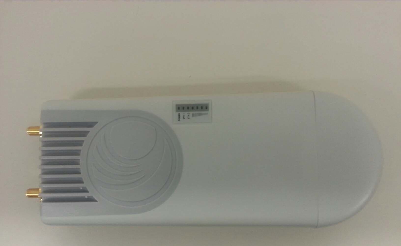
Click to zoom
Application Details
- Equipment Class
- DTS - Digital Transmission System
- Date of Grant
- Mar 24, 2014
- Application Purpose
- Original Equipment
- Date of Application
- Mar 24, 2014
- Equipment Note
- Dual Channel 2.4GHz MIMO Station and Connectorized Station
- Frequency Range
- 2427.00000000 - 2452.00000000
- Company
- Cambium Networks Inc.
- Country
- United States
Documents & Files
Document Text
Text extracted from the exhibit documents filed with the FCC. Open a document above to read the original.
Users Manual
System Release 1.4.3 • Product Description • System Planning • Configuration • Operation and Troubleshooting • Legal and Reference Information User Guide CAMBIUM NETWORKS Accuracy While reasonable efforts have been made to assure the accuracy of this document, Cambium Networks assumes no liability resulting from any inaccuracies or omissions in this document, or from use of the information obtained herein. Cambium reserves the right to make changes to any products described herein to improve reliability, function, or design, and reserves the right to revise this document and to make changes from time to time in content hereof with no obligation to notify any person of revisions or changes. Cambium does not assume any liability arising out of the application or use of any product, software, or circuit described herein; neither does it convey license under its patent rights or the rights of others. It is possible that this publication may contain references to, or information about Cambium products (machines and programs), programming, or services that are not announced in your country. Such references or information must not be construed to mean that Cambium intends to announce such Cambium products, programming, or services in your country. Copyrights This document, Cambium products, and 3 rd Party software products described in this document may include or describe copyrighted Cambium and other 3 rd Party supplied computer programs stored in semiconductor memories or other media. Laws in the United States and other countries preserve for Cambium, its licensors, and other 3 rd Party supplied software certain exclusive rights for copyrighted material, including the exclusive right to copy, reproduce in any form, distribute and make derivative works of the copyrighted material. Accordingly, any copyrighted material of Cambium, its licensors, or the 3 rd Party software supplied material contained in the Cambium products described in this document may not be copied, reproduced, reverse engineered, distributed, merged or modified in any manner without the express written permission of Cambium. Furthermore, the purchase of Cambium products shall not be deemed to grant either directly or by implication, estoppel, or otherwise, any license under the copyrights, patents or patent applications of Cambium or other 3rd Party supplied software, except for the normal non-exclusive, royalty free license to use that arises by operation of law in the sale of a product. Restrictions Software and documentation are copyrighted materials. Making unauthorized copies is prohibited by law. No part of the software or documentation may be reproduced, transmitted, transcribed, stored in a retrieval system, or translated into any language or computer language, in any form or by any means, without prior written permission of Cambium. License Agreements The software described in this document is the property of Cambium and its licensors. It is furnished by express license agreement only and may be used only in accordance with the terms of such an agreement. High Risk Materials Cambium and its supplier(s) specifically disclaim any express or implied warranty of fitness for any high risk activities or uses of its products including, but not limited to, the operation of nuclear facilities, aircraft navigation or aircraft communication systems, air traffic control, life support, or weapons systems (“High Risk Use”). Any High Risk is unauthorized, is made at your own risk and you shall be responsible for any and all losses, damage or claims arising out of any High Risk Use. © 2014 Cambium Networks Limited. All Rights Reserved. 2 CAMBIUM NETWORKS Safety and regulatory information This section describes important safety and regulatory guidelines that must be observed by personnel installing or operating ePMP equipment. IMPORTANT SAFETY INFORMATION Warning To prevent loss of life or physical injury, observe the safety guidelines in this section. Power lines Exercise extreme care when working near power lines. Working at heights Exercise extreme care when working at heights. Grounding and protective earth Connectorized ePMP devices must be properly grounded to protect against lightning. It is the user’s responsibility to install the equipment in accordance with national regulations. In the USA, follow Section 810 of the National Electric Code, ANSI/NFPA No.70-1984 (USA). In Canada, follow Section 54 of the Canadian Electrical Code. These codes describe correct installation procedures for grounding the outdoor unit, mast, lead-in wire and discharge unit, size of grounding conductors and connection requirements for grounding electrodes. Other regulations may apply in different countries and therefore it is recommended that installation be contracted to a professional installer. Powering down before servicing Always power down and unplug the equipment before servicing. Primary disconnect device The ePMP power supply is the primary disconnect device. External cables Safety may be compromised if outdoor rated cables are not used for connections that will be exposed to the outdoor environment. RF exposure near the antenna Strong radio frequency (RF) fields will be present close to the antenna when the transmitter is on. Always turn off the power to the ePMP device before undertaking maintenance activities in front of the antenna. Minimum separation distances Install the ePMP device so as to provide and maintain the minimum separation distances from all persons. The minimum separation distances for each frequency variant are specified in Calculated distances and power compliance margins on page 263. 3 CAMBIUM NETWORKS IMPORTANT REGULATORY INFORMATION The ePMP product is certified as an unlicensed device in frequency bands where it is not allowed to cause interference to licensed services (called primary users of the bands). Radar avoidance In countries where radar systems are the primary band users, the regulators have mandated spec…
Text truncated - open the document above for the full version.
RF Exposure Info
CAMBIUM NETWORKS Calculation of power density Note The following calculation is based on the ANSI IEEE C95.1-1991 method, as that provides a worst case analysis. Details of the assessment to EN50383:2002 can be provided, if required. Peak power density in the far field of a radio frequency point source is calculated as follows: Where: Is: S power density in W/m 2 P maximum average transmit power capability of the radio, in W G total Tx gain as a factor, converted from dB d distance from point source, in m Rearranging terms to solve for distance yields: Calculated distances and power compliance margins Table 84 shows calculated minimum separation distances, recommended distances and resulting margins for each frequency band and antenna combination. These are conservative distances that include compliance margins. At these and greater separation distances, the power density from the RF field is below generally accepted limits for the general population. Explanation of terms used in Table 84: Tx burst – maximum average transmit power in burst (Watt) P – maximum average transmit power capability of the radio (Watt) G – total transmit gain as a factor, converted from dB S – power density (W/m 2 ) d – minimum distance from point source (meters) R – recommended distances (meters) C – compliance factor 2 4 . d GP S π = S GP d .4 . π = 263 CAMBIUM NETWORKS Table 84 Power compliance margins, 5 GHz Band Antenna P (W) G S (W/m 2 ) d (m) R (m) C 5 GHz Integrated, 13 dBi 0.199 20 10 0.18 .4 51 5 GHz Connectorized, 15 dBi 0.199 31.6 10 0.22 .4 32 Table 85 Power compliance margins, 2.4 GHz, AP Conn Type Channel Bandwidth Antenna P (W) G S (W/m 2 ) d (m) R (m) C PMP 20 MHz Connectorized, 8 dBi Omni 0.631 6.3 10 0.18 0.4 50.5 PMP 40 MHz Connectorized, 8 dBi Omni 0.631 6.3 10 0.18 0.4 50.5 PMP 20 MHz Connectorized, 17 dBi Sector 0.079 50.1 10 0.18 0.4 50.5 PMP 40 MHz Connectorized, 17 dBi Sector 0.032 50.1 10 0.11 0.3 71.3 PTP 20 MHz Connectorized, 25 dBi Dish 0.003 316.2 10 0.08 0.2 63.2 PTP 40 MHz Connectorized, 25 dBi Dish 0.003 316.2 10 0.08 0.2 63.2 Table 86 Power compliance margins, 2.4 GHz, STA Conn Type Channel Bandwidth Antenna P (W) G S (W/m 2 ) d (m) R (m) C PMP 20 MHz Connectorized, 8 dBi Omni 0.631 6.3 10 0.18 0.4 50.5 PMP 40 MHz Integrated, 12 dBi Patch 0.251 15.8 10 0.18 0.4 50.5 PMP 20 MHz Connectorized, 17 dBi Sector 0.079 50.1 10 0.18 0.4 50.5 PMP 40 MHz Connectorized, 19 dBi Panel 0.050 79.4 10 0.18 0.4 50.5 PMP 20 MHz Connectorized, 25 dBi Dish 0.010 316.2 10 0.16 0.4 63.5 PMP 40 MHz Connectorized, 8 dBi Omni 0.100 6.3 10 0.07 0.2 79.6 PMP 20 MHz Integrated, 12 dBi Patch 0.050 15.8 10 0.08 0.2 63.2 PMP 40 MHz Connectorized, 17 dBi Sector 0.025 50.1 10 0.10 0.2 39.9 PMP 20 MHz Connectorized, 19 dBi Panel 0.020 79.4 10 0.11 0.3 71.3 PMP 40 MHz Connectorized, 25 dBi Dish 0.006 316.2 10 0.13 0.3 56.7 PTP 20 MHz Integrated, 12 dBi Patch 0.398 15.8 10 0.22 0.4 31.9 264 CAMBIUM NETWORKS PTP 40 MHz Connectorized, 17 dBi Sector 0.158 50.1 10 0.25 0.5 39.5 PTP 20 MHz Connectorized, 19 dBi Panel 0.050 79.4 10 0.18 0.4 50.5 PTP 40 MHz Connectorized, 25 dBi Dish 0.010 316.2 10 0.16 0.4 63.5 PTP 20 MHz Integrated, 12 dBi Patch 0.050 15.8 10 0.08 0.2 63.2 PTP 40 MHz Connectorized, 17 dBi Sector 0.025 50.1 10 0.10 0.2 39.9 PTP 20 MHz Connectorized, 19 dBi Panel 0.020 79.4 10 0.11 0.3 71.3 PTP 40 MHz Connectorized, 25 dBi Dish 0.006 316.2 10 0.13 0.3 56.7 Note Gain of antenna in dBi = 10*log(G). The regulations require that the power used for the calculations is the maximum power in the transmit burst subject to allowance for source-based time-averaging. At 2.4 GHz, 5.4 GHz and EU 5.8 GHz, the products are generally limited to a fixed EIRP which can be achieved with the Integrated Antenna. The calculations above assume that the maximum EIRP allowed by the regulations is being transmitted. Note If there are no EIRP limits in the country of deployment, use the distance calculations for FCC 5.8 GHz for all frequency bands. 265
Test Report
166 South Carter, Genoa City, WI 53128 Page 1 of 614 Company: Cambium Networks Model Tested: C024900P021A & C024900P031A Report Number: 19738 DLS Project: 6334 i. Cover Page Code of Federal Regulations 47 Part 15 – Radio Frequency Devices Subpart C – Intentional Radiators Section 15.247 Operation within the bands 902 - 928 MHz, 2400 - 2483.5 MHz, 5725 - 5875 MHz, and 24.0 - 24.25 GHz. PART 1 - thru Section B6.0 THE FOLLOWING MEETS THE ABOVE TEST SPECIFICATION Formal Name: EPMP Station 2.4 GHz OFDM MIMO Radio Kind of Equipment: Point-to-Point or Point-to-Multipoint Digital Transmission Transceiver Frequency Range: 2412 to 2462 MHz (20 MHz bandwidth) 2427 to 2452 MHz (40 MHz bandwidth) Please see the Users' Manual for the channel specifications for use with the Dish antenna. Test Configuration: Stand-alone Model Number(s): Connectorized: C024900P021A, C024900A021A Integrated: C024900P031A, C024900C031A Model(s) Tested: Connectorized: C024900P021A Integrated: C024900P031A Serial Number(s): Connectorized: MAC Address: 000456C2CE92 Integrated: MAC Address: 000456C2CE05 Date of Tests: January to March, 2014 (non-consecutive days) Test Conducted For: Cambium Networks 3800 Golf Road, Suite 360 Rolling Meadows, IL 60008, USA NOTICE: “This test report relates only to the items tested and must not be used by the client to claim product endorsement by NVLAP or any agency of the U.S. Government”. Please see the "Description of Test Sample" page listed inside of this report. © Copyright 1983 – 2014, D.L.S. Electronic Systems, Inc. COPYRIGHT NOTICE This report must not be reproduced (except in full), without the approval of D.L.S. Electronic Systems, Inc. 166 South Carter, Genoa City, WI 53128 Page 2 of 614 Company: Cambium Networks Model Tested: C024900P021A & C024900P031A Report Number: 19738 DLS Project: 6334 ii. Signature Page SIGNATURE PAGE Tested By: Craig Brandt Senior Test Engineer Reviewed By: William Stumpf OATS Manager Approved By: Brian Mattson General Manager 166 South Carter, Genoa City, WI 53128 Page 3 of 614 Company: Cambium Networks Model Tested: C024900P021A & C024900P031A Report Number: 19738 DLS Project: 6334 iii. Table of Contents Table of Contents i. Cover Page ............................................................................................................................................................. 1 ii. Signature Page ....................................................................................................................................................... 2 iii. Table of Contents .................................................................................................................................................. 3 iv. NVLAP Certificate of Accreditation ..................................................................................................................... 5 1.0 Summary of Test Report ............................................................................................................................... 6 2.0 Introduction ................................................................................................................................................... 7 3.0 Test Facilities ................................................................................................................................................ 7 4.0 Description of Test Sample ........................................................................................................................... 7 5.0 Test Equipment .............................................................................................................................................. 9 6.0 Test Arrangements ...................................................................................................................................... 10 7.0 Test Conditions ............................................................................................................................................ 10 8.0 Modifications Made To EUT for Compliance ............................................................................................ 11 9.0 Additional Descriptions ............................................................................................................................... 11 10.0 Results ......................................................................................................................................................... 11 11.0 Conclusion ................................................................................................................................................... 11 Appendix A – Test Photos ........................................................................................................................................ 12 Appendix B – Measurement Data ............................................................................................................................ 17 B1.0 DTS Bandwidth – 6 dB bandwidth - Conducted ...................................................................... 17 B1.0a - with Omni Antenna ................................................................................................................ 18 B1.0b - w-Integral Patch using power settings from radiated output power measurements ............... 24 B2.0 Fundamental Emission Output Power - Conducted .................................................................. 30 B2.0a - with Omni Antenna ................................................................................................................ 31 B2.0b - with Integral Patch Antenna ................................................................................................... 37 B2.0c - with Sector Antenna ............................................................................................................... 51 B2.0d - with Panel Antenna ............................................................................................…
Text truncated - open the document above for the full version.
Test Report
166 South Carter, Genoa City, WI 53128 Page 1 of 614 Company: Cambium Networks Model Tested: C024900P021A & C024900P031A Report Number: 19738 DLS Project: 6334 i. Cover Page Code of Federal Regulations 47 Part 15 – Radio Frequency Devices Subpart C – Intentional Radiators Section 15.247 Operation within the bands 902 - 928 MHz, 2400 - 2483.5 MHz, 5725 - 5875 MHz, and 24.0 - 24.25 GHz. PART 2 - Sections B7.0 to B12.0 THE FOLLOWING MEETS THE ABOVE TEST SPECIFICATION Formal Name: EPMP Station 2.4 GHz OFDM MIMO Radio Kind of Equipment: Point-to-Point or Point-to-Multipoint Digital Transmission Transceiver Frequency Range: 2412 to 2462 MHz (20 MHz bandwidth) 2427 to 2452 MHz (40 MHz bandwidth) Please see the Users' Manual for the channel specifications for use with the Dish antenna. Test Configuration: Stand-alone Model Number(s): Connectorized: C024900P021A, C024900A021A Integrated: C024900P031A, C024900C031A Model(s) Tested: Connectorized: C024900P021A Integrated: C024900P031A Serial Number(s): Connectorized: MAC Address: 000456C2CE92 Integrated: MAC Address: 000456C2CE05 Date of Tests: January to March, 2014 (non-consecutive days) Test Conducted For: Cambium Networks 3800 Golf Road, Suite 360 Rolling Meadows, IL 60008, USA NOTICE: “This test report relates only to the items tested and must not be used by the client to claim product endorsement by NVLAP or any agency of the U.S. Government”. Please see the "Description of Test Sample" page listed inside of this report. © Copyright 1983 – 2014, D.L.S. Electronic Systems, Inc. COPYRIGHT NOTICE This report must not be reproduced (except in full), without the approval of D.L.S. Electronic Systems, Inc. 166 South Carter, Genoa City, WI 53128 Page 2 of 614 Company: Cambium Networks Model Tested: C024900P021A & C024900P031A Report Number: 19738 DLS Project: 6334 ii. Signature Page SIGNATURE PAGE Tested By: Craig Brandt Senior Test Engineer Reviewed By: William Stumpf OATS Manager Approved By: Brian Mattson General Manager 166 South Carter, Genoa City, WI 53128 Page 3 of 614 Company: Cambium Networks Model Tested: C024900P021A & C024900P031A Report Number: 19738 DLS Project: 6334 iii. Table of Contents Table of Contents i. Cover Page ............................................................................................................................................................. 1 ii. Signature Page ....................................................................................................................................................... 2 iii. Table of Contents .................................................................................................................................................. 3 iv. NVLAP Certificate of Accreditation ..................................................................................................................... 5 1.0 Summary of Test Report ............................................................................................................................... 6 2.0 Introduction ................................................................................................................................................... 7 3.0 Test Facilities ................................................................................................................................................ 7 4.0 Description of Test Sample ........................................................................................................................... 7 5.0 Test Equipment .............................................................................................................................................. 9 6.0 Test Arrangements ...................................................................................................................................... 10 7.0 Test Conditions ............................................................................................................................................ 10 8.0 Modifications Made To EUT for Compliance ............................................................................................ 11 9.0 Additional Descriptions ............................................................................................................................... 11 10.0 Results ......................................................................................................................................................... 11 11.0 Conclusion ................................................................................................................................................... 11 Appendix A – Test Photos ........................................................................................................................................ 12 Appendix B – Measurement Data ............................................................................................................................ 17 B1.0 DTS Bandwidth – 6 dB bandwidth - Conducted ...................................................................... 17 B1.0a - with Omni Antenna ................................................................................................................ 18 B1.0b - w-Integral Patch using power settings from radiated output power measurements ............... 24 B2.0 Fundamental Emission Output Power - Conducted .................................................................. 30 B2.0a - with Omni Antenna ................................................................................................................ 31 B2.0b - with Integral Patch Antenna ................................................................................................... 37 B2.0c - with Sector Antenna ............................................................................................................... 51 B2.0d - with Panel Antenna .......................................................................................…
Text truncated - open the document above for the full version.
Test Setup Photos
166 South Carter, Genoa City, WI 53128 Page 1 of 5 Manufacturer: Cambium Networks Model Tested: C024900P021A & C024900P031A Project Number: 6334 Test Photos Photo Information and Test Setup: Item0: Cambium Networks PMP450SM 2.4 GHz MIMO Radio, Model C024900P021A or C024900P031A Item1: Phihong Power Supply PSA-15M-300(SM) Item2: Unshielded AC Power Cord to Power Supply - .9 meters long Item3: Unshielded CAT 5e Ethernet Cable - not terminated - 8 meters long Item4: Unshielded CAT 5e POE Cable - 1.5 meters long Radiated - Front, below 1 GHz 166 South Carter, Genoa City, WI 53128 Page 2 of 5 Manufacturer: Cambium Networks Model Tested: C024900P021A & C024900P031A Project Number: 6334 Test Photos Radiated - Back, below 1 GHz 166 South Carter, Genoa City, WI 53128 Page 3 of 5 Manufacturer: Cambium Networks Model Tested: C024900P021A & C024900P031A Project Number: 6334 Test Photos Radiated - above 1 GHz RF Conducted 166 South Carter, Genoa City, WI 53128 Page 4 of 5 Manufacturer: Cambium Networks Model Tested: C024900P021A & C024900P031A Project Number: 6334 Test Photos AC Line Conducted - Front 166 South Carter, Genoa City, WI 53128 Page 5 of 5 Manufacturer: Cambium Networks Model Tested: C024900P021A & C024900P031A Project Number: 6334 Test Photos AC Line Conducted - Back
Contact Information
Applicant
Steven M. Payne(R.F. Principle Staff Engineer)
Test Firm
DLS Electronic Systems, Inc.William Stumpf
Technical Specifications
| # | Rule Parts | Frequency Range | Power Output |
|---|---|---|---|
| 2 | 15C | 2.43 GHz - 2.45 GHz | 100.00 mW |
Other Applications from Cambium Networks Inc.
Z8H89FT0090
Apr 21, 2026X7-56X Indoor Wi-Fi 7 Tri-band 4x4 AP, 60deg
Equipment Class
6ID - 15E 6 GHz Low Power Indoor Access PointZ8H89FT0083
Sep 17, 20246092HH
Equipment Class
NII - Unlicensed National Information Infrastructure TX
Z8H89FT0084
Feb 19, 20246091HH
Equipment Class
NII - Unlicensed National Information Infrastructure TX
Z8H89FT0081
Dec 14, 20236084HH
Equipment Class
NII - Unlicensed National Information Infrastructure TX
Z8H89FT0082
Dec 03, 20236094HH
Equipment Class
NII - Unlicensed National Information Infrastructure TX