Z8VSP-21BTBluetooth Speaker
DAZA Electronics Company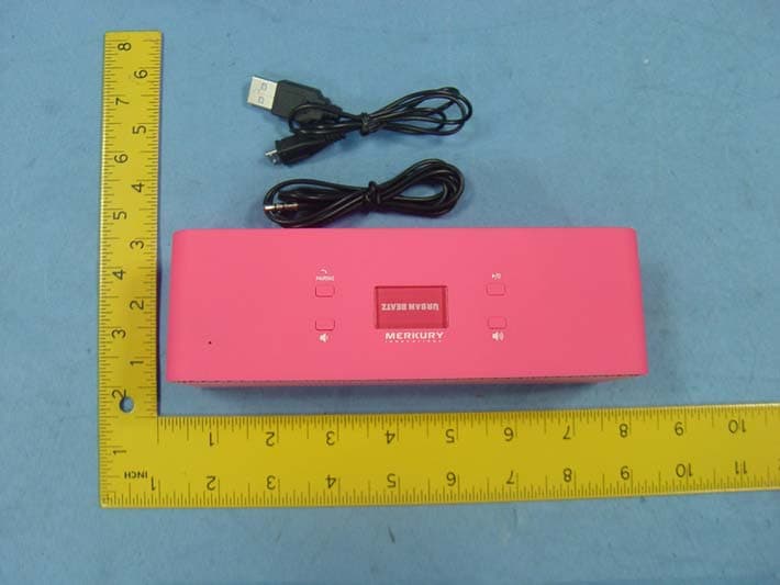
Click to zoom
Application Details
- Equipment Class
- DSS - Part 15 Spread Spectrum Transmitter
- Date of Grant
- Oct 22, 2013
- Application Purpose
- Original Equipment
- Date of Application
- Oct 22, 2013
- Equipment Note
- Bluetooth Speaker
- Frequency Range
- 2402.00000000 - 2480.00000000
- Company
- DAZA Electronics Company
- Country
- China
Documents & Files
Document Text
Text extracted from the exhibit documents filed with the FCC. Open a document above to read the original.
Users Manual
SP-21BT speaker Manual Thank you for using our BT speaker! This unit provides rich quality sound in order to provide you with a good experience. Please read this User Manual before using this product. Thank you so much for attention. Operation: 1.Bluetooth Searching Turn ON the POWER, the device will start work automatically. The light will flash quickly and enter reconnection condition.It will be fail after 18s reconnection.Then the device will start work automatically (the red and blue light will be flash on the front of the speaker). If you want to pair quickly,should be press long about 4s.Then you can search the device “.....” by your mobile phone. If a password is needed when pairing, please input “0000”, waiting for 3-5 seconds again. Then the connection between your mobile phone and the device is successful, with the screen displaying.Please turn on the device again when it enter into the sleep mode after disconnecting bluetooth around 5 mins. After successful connection, you start your media player on your mobile phone, then you can hear the nice music from the BT speaker. The blue light slow at this time.“ + ”is increase volume “—”is decrease volume is pause。 This device has a indicate voice “du, du...” when there is a call coming. You can press “” button to answer the phone call. During the call, you can press button to switch between your mobile answering and BT answering. Press “” button again to hang up the phone call. If u wouldn’t want to answer the call, just press to decline and ignore. LINE IN function: Insert the 3.5MM LINE IN Cable into the device and connect it with your computer/ mobile phone or other devices’ audio output port, the Bluetooth will turn off and enter into LINE IN mode automatically , When you want to adjust volume, press and hold the button to increase the volume, press and hold the button will reduce the volume. Charging: When this device is short of power the red light will be flash. please insert the Charging Cable into the “DC 5V” port, while the other end USB connecting with the computer or adapter 5V, while the red light will be still light ,it is full, it will display Note: 1.please charging in time,or it will be shutdown when the red light indicates low power(red light flash quickly) 2.Please use the charging cable support by us,If used with other data 3.transmission on startup of the MICRO USB charging line charging through the computer will automatically disconnect. Product parameters: BT version number:2.0 Charging voltage: DC-5V Charging current: 300MA Working voltage: 3.7V Battery capacity: 500MAH Frequency range:20-20KHZ Speaker impedance:4Ω / 3W * 2 Standby time: 5Hours (based on 80% volume) Distortion degree: ≤5% FCC STATEMENT 1. This device complies with Part 15 of the FCC Rules. Operation is subject to the following two conditions: (1)This device may not cause harmful interference, and (2)This device must accept any interference received, including interference that may cause undesired operation. 2. Changes or modifications not expressly approved by the party responsible for compliance could void the user’s authority to operate the equipment. FCC Radiation Exposure Statement: The device has been evaluated to meet general RF exposure requirement. The device can be used in portable exposure condition without RF striction. NOTE: This equipment has been tested and found to comply with the limits for a Class B digital, pursuant to Part 15 or the FCC Rules. These limits are designed to provide reasonable protection against harmful interference in a residential installation. This equipment generates, uses and can radiate radio frequency energy and, if not installed and used in accordance with the instructions, may cause harmful interference to radio communications, However, there is no guarantee that interference will not occur in a particular installation. If the equipment does cause harmful interference to radio or television reception, which can be determined by turning the equipment off and on, the user is encouraged to try to correct the interference by one or more of the following measures: --- Reorient or relocate the receiving antenna. --- Increase the separation between the equipment and receiver. --- Connect the equipment into an outlet on a circuit different from that to which the receiver is connected. --- Consult the dealer or an experienced radio/ TV technician for help.
Attestation Statements
Daza Electronics Company October 8, 2013 To: Federal Communications Commission Authorization and Evaluation Division 7435 Oakland Mills Road Columbia, MD FCC ID: Z8VSP-21BT To Whom It May Concern: This letter is to ascertain that Daza Electronics Company (Product:Bluetooth speaker Model name: SP-21BT) has been the units used for conducting FCC compliance testing, the DoC part will be tested by FCC recognized test lab. If you have any question or concerns, pls. contact us. Sincerely, Client’s signature: Client’s name / title: Yu Zhou / Engineer Contact information / address: Bldg G, Xinmusheng Low Carbon Industrial Park, NO.6 Xinmu Road Pinghu, Shenzhen, China
Cover Letter(s)
Daza Electronics Company October 8, 2013 To: SIEMIC, INC. 775 Montague Expressway Milpitas , CA 95035 USA Dear Sir/Madam, Re: Project and Product Certification Representative Authorization Letter We , Daza Electronics Company hereby authorize SIEMIC, INC. to act as a Certification Body for certifying for the following project(s): Product Description: Bluetooth speaker Model name: SP-21BT FCC ID: Z8VSP-21BT We affirm that between SIEMIC and Daza Electronics Company , any difference in understanding, including test plan, measurement methods, applicable standards and relevant procedures and processes have been resolved prior to commencement of testing activities. Sincerely, Client’s signature: Client’s name / title: Yu Zhou / Engineer Contact information / address: Bldg G, Xinmusheng Low Carbon Industrial Park, NO.6 Xinmu Road Pinghu, Shenzhen, China
Cover Letter(s)
SCS-F19: Confidentiality Request Letter Page 1 of 1 Rev 2.0 Daza Electronics Company October 8, 2013 To: Federal Communications Commission Authorization and Evaluation Division 7435 Oakland Mills Road Columbia, MD Confidentiality Request regarding application for certification of FCC ID: Z8VSP-21BT We hereby request confidential treatment of information accompanying this application as outlined below: - Block Diagram - Operational Description - Schematic The above materials contain trade secrets and proprietary information not customarily released to the public. The public disclosure of these materials may be harmful to the applicant and provide unjustified benefits to its competitors. The applicant understands that pursuant to Section 0.457 & 0.459 of the Rules, disclosure of this application and all accompanying documentation will not be made before the date of the Grant for this application. Client’s signature: Client’s name / title: Yu Zhou / Engineer Contact information / address: Bldg G, Xinmusheng Low Carbon Industrial Park, NO.6 Xinmu Road Pinghu, Shenzhen, China
ID Label/Location Info
FCC Certification Label Location Sample Label location
ID Label/Location Info
FCC Certification label Sample FCC ID: Z8VSP-21BT This device complies with Part 15 of the FCC Rules. Operation is subject to the following two conditions: (1) This device may not cause harmful interference, and (2) This device must accept any interference received, including interference that may cause undesired operation.
Internal Photos
Antenna
RF Exposure Info
FCC ID : Z8VSP-21BT Portable device According to §15.247(e)(i) and §1.1307(b)(1), systems operating under the provisions of this section shall be operated in a manner that ensures that the public is not exposed to radio frequency energy level in excess of the Commission’s guidelines. According to KDB 447498 D01 General RF Exposure Guidance v05, section 4.3.1 The 1-g and 10-g SAR test exclusion thresholds for 100 MHz to 6 GHz at test separation distances ≤ 50 mm are determined by: [(max. power of channel, including tune-up tolerance, mW)/(min. test separation distance, mm)] · [√f(GHz)] ≤ 3.0 for 1-g SAR and ≤ 7.5 for 10-g extremity SAR, 16 where f(GHz) is the RF channel transmit frequency in GHz Power and distance are rounded to the nearest mW and mm before calculation 17 The result is rounded to one decimal place for comparison The test exclusions are applicable only when the minimum test separation distance is ≤ 50 mm and for transmission frequencies between 100 MHz and 6 GHz. When the minimum test separation distance is < 5 mm, a distance of 5 mm is applied to determine SAR test exclusion. Frequency (MHz) Peak Output Power (dBm) Peak Output Power (mW) Calculation Value Threshold Value 2402 -0.63 0.86 0.266 3.0 2441 -0.67 0.85 0.265 3.0 2480 0.08 1.01 0.318 3.0 Threshold at which no SAR required is ≤ 3.0 for 1-g SAR, Separation distance is 5mm. Conclusion: No SAR is required. SIMULTANEOUS TRANSMISSION EVALUATION N/A
Test Report
Page 1 of 88 FCC ID: Z8VSP-21BT ACCURATE TECHNOLOGY CO. LTD REPORT NO. ATE20132076 APPLICATION CERTIFICATION On Behalf of Daza Electronics Company Bluetooth speaker Model No.: SP-21BT FCC ID: Z8VSP-21BT Prepared for : Daza Electronics Company Address : Bldg G, Xinmusheng Low Carbon Industrial Park, NO.6 Xinmu Road Pinghu, Shenzhen, China Prepared by : ACCURATE TECHNOLOGY CO. LTD Address : F1, Bldg. A, Changyuan New Material Port, Keyuan Rd. Science & Industry Park, Nanshan, Shenzhen, Guangdong P.R. China Tel: (0755) 26503290 Fax: (0755) 26503396 Report Number : ATE20132076 Date of Test : September 26-30, 2013 Date of Report : October 8, 2013 Page 2 of 88 FCC ID: Z8VSP-21BT ACCURATE TECHNOLOGY CO. LTD REPORT NO. ATE20132076 TABLE OF CONTENTS Description Page Test Report Certification 1. GENERAL INFORMATION .......................................................................................................... 5 1.1. Description of Device (EUT)....................................................................................................................5 1.2. Description of Test Facility ......................................................................................................................6 1.3. Measurement Uncertainty.........................................................................................................................6 2. MEASURING DEVICE AND TEST EQUIPMENT ..................................................................... 7 3. OPERATION OF EUT DURING TESTING ................................................................................. 8 3.1. Operating Mode........................................................................................................................................8 3.2. Configuration and peripherals ..................................................................................................................8 4. TEST PROCEDURES AND RESULTS ......................................................................................... 9 5. 20DB BANDWIDTH TEST............................................................................................................ 10 5.1. Block Diagram of Test Setup..................................................................................................................10 5.2. The Requirement For Section 15.247(a)(1)............................................................................................10 5.3. EUT Configuration on Measurement .....................................................................................................10 5.4. Operating Condition of EUT ..................................................................................................................10 5.5. Test Procedure ........................................................................................................................................11 5.6. Test Result ..............................................................................................................................................11 6. CARRIER FREQUENCY SEPARATION TEST........................................................................ 15 6.1. Block Diagram of Test Setup..................................................................................................................15 6.2. The Requirement For Section 15.247(a)(1)............................................................................................15 6.3. EUT Configuration on Measurement .....................................................................................................15 6.4. Operating Condition of EUT ..................................................................................................................15 6.5. Test Procedure ........................................................................................................................................16 6.6. Test Result ..............................................................................................................................................16 7. NUMBER OF HOPPING FREQUENCY TEST ......................................................................... 20 7.1. Block Diagram of Test Setup..................................................................................................................20 7.2. The Requirement For Section 15.247(a)(1)(iii)......................................................................................20 7.3. EUT Configuration on Measurement .....................................................................................................20 7.4. Operating Condition of EUT ..................................................................................................................20 7.5. Test Procedure ........................................................................................................................................21 7.6. Test Result ..............................................................................................................................................21 8. DWELL TIME TEST ..................................................................................................................... 23 8.1. Block Diagram of Test Setup..................................................................................................................23 8.2. The Requirement For Section 15.247(a)(1)(iii)......................................................................................23 8.3. EUT Configuration on Measurement .....................................................................................................23 8.4. Operating Condition of EUT ..................................................................................................................23 8.5. Test Procedure ........................................................................................................................................24 8.6. Test Result ..…
Text truncated - open the document above for the full version.
Test Setup Photos
Conducted Emission test Radiated emissions test 30MHz - 1GHz Radiated emissions test > 1GHz
Contact Information
Applicant
Yu Zhou(Engineer)
Test Firm
Accurate Technology Co., Ltd.Sean Liu
Technical Specifications
| # | Rule Parts | Frequency Range | Power Output |
|---|---|---|---|
| 1 | 15C | 2.40 GHz - 2.48 GHz | 1.01 mW |
Other Applications from DAZA Electronics Company

Z8VR15BT
Sep 02, 2014BT headphone
Equipment Class
DTS - Digital Transmission System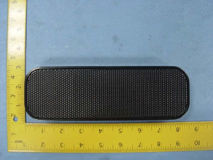
Z8VSP-25BT
Aug 03, 2014Bluetooth Speaker
Equipment Class
DSS - Part 15 Spread Spectrum Transmitter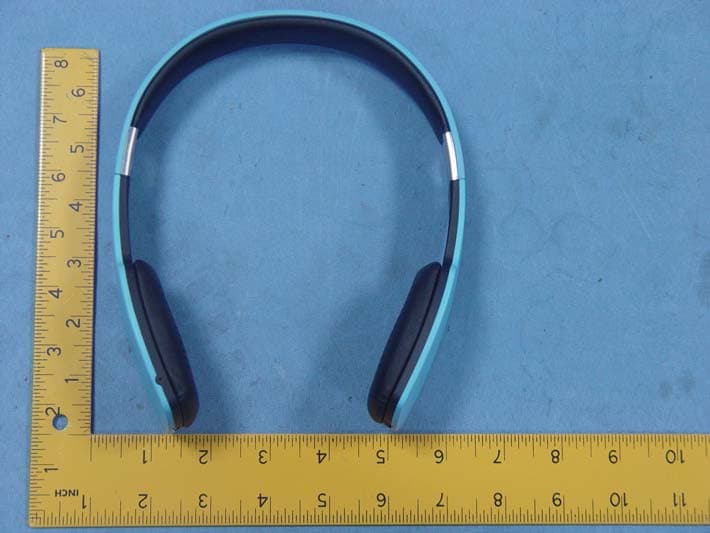
Z8VR-15BT
Jan 12, 2014Bluetooth Headphone
Equipment Class
DSS - Part 15 Spread Spectrum Transmitter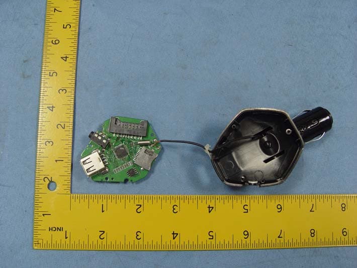
Z8VF-208A
Nov 07, 2013FM Transmitter
Equipment Class
DXX - Part 15 Low Power Communication Device Transmitter
Z8VMID
Dec 01, 2011MID
Equipment Class
DTS - Digital Transmission System